Beer F.P., Johnston E.R., DeWolf J.T., Mazurek D.F. Mechanics of Materials
Подождите немного. Документ загружается.

Apago PDF Enhancer
477
Problems
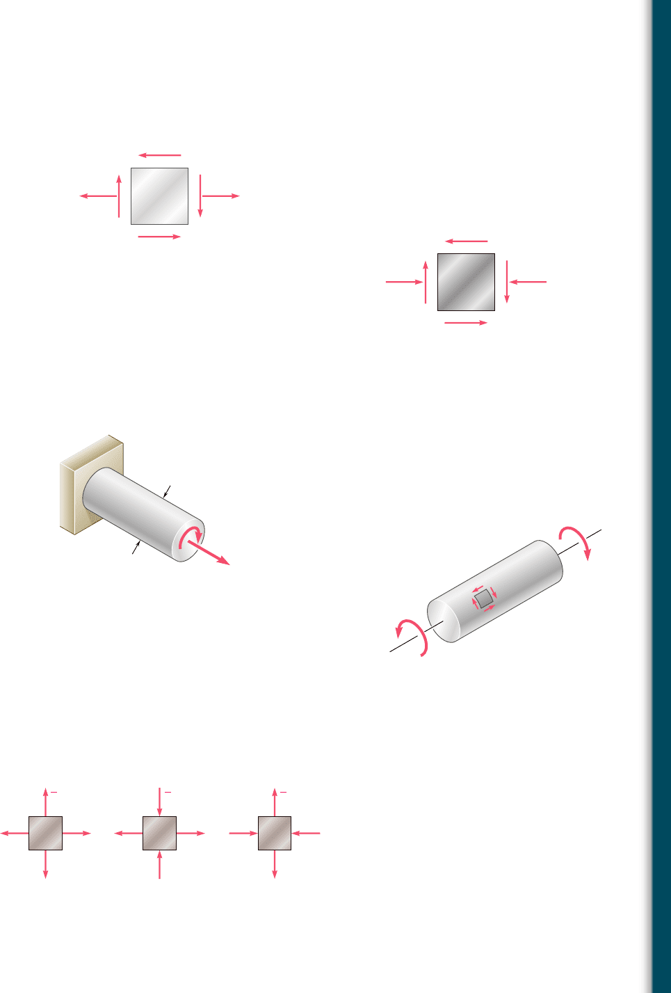
7.93 The state of plane stress shown will occur at a critical point in an
aluminum casting that is made of an alloy for which s
UT
5 10 ksi
and s
UC
5 25 ksi. Using Mohr’s criterion, determine the shearing
stress t
0
for which failure should be expected.
8 ksi
0
Fig. P7.93
80 MP
a
0
Fig. P7.94
7.94 The state of plane stress shown will occur at a critical point in
a pipe made of an aluminum alloy for which s
UT
5 75 MPa and
s
UC
5 150 MPa. Using Mohr’s criterion, determine the shearing
stress t
0
for which failure should be expected.
7.95 The cast-aluminum rod shown is made of an alloy for which s
UT
5
60 MPa and s
UC
5 120 MPa. Using Mohr’s criterion, determine the
magnitude of the torque T for which failure should be expected.
26 kN
32 mm
T
A
B
Fig. P7.95
7.96 The cast-aluminum rod shown is made of an alloy for which s
UT
5
70 MPa and s
UC
5 175 MPa. Knowing that the magnitude T of the
applied torques is slowly increased and using Mohr’s criterion, deter-
mine the shearing stress t
0
that should be expected at rupture.
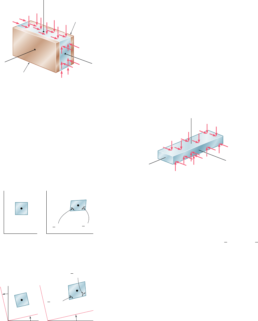
7.97 A machine component is made of a grade of cast iron for which
s
UT
5 8 ksi and s
UC
5 20 ksi. For each of the states of stress
shown, and using Mohr’s criterion, determine the normal stress s
0
at which rupture of the component should be expected.
T
'
T
0
Fig. P7.96
1
2
0
0
1
2
0
0
1
2
0
0
(a)(b)(c)
Fig. P7.97
bee80288_ch07_436-511.indd Page 477 11/19/10 2:55:30 PM user-f499bee80288_ch07_436-511.indd Page 477 11/19/10 2:55:30 PM user-f499 /Users/user-f499/Desktop/Temp Work/Don't Delete Job/MHDQ251:Beer:201/ch07/Users/user-f499/Desktop/Temp Work/Don't Delete Job/MHDQ251:Beer:201/ch07
Apago PDF Enhancer
478
Transformations of Stress and Strain
7.9 STRESSES IN THIN-WALLED PRESSURE VESSELS
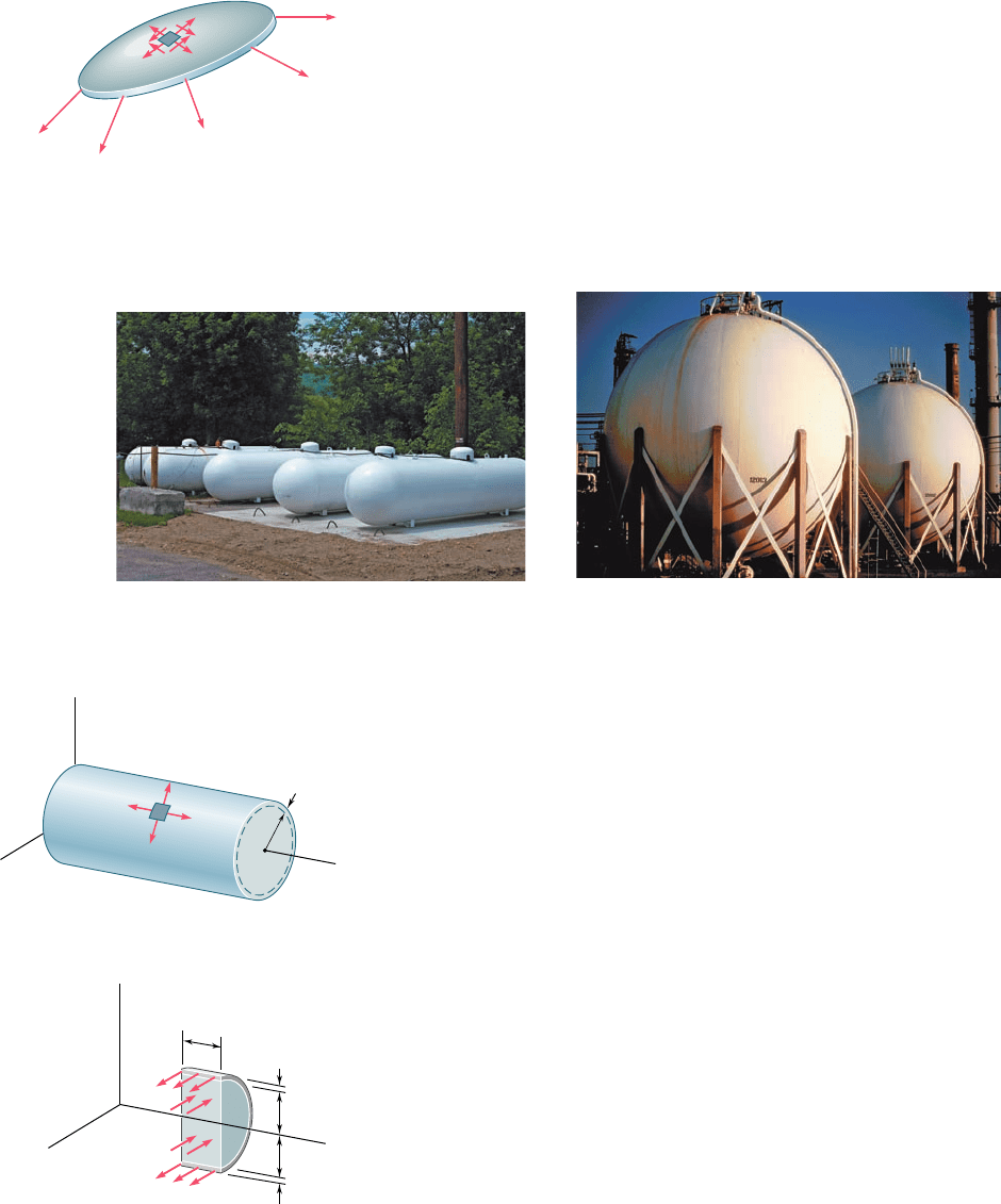
Thin-walled pressure vessels provide an important application of the
analysis of plane stress. Since their walls offer little resistance to
bending, it can be assumed that the internal forces exerted on a given
portion of wall are tangent to the surface of the vessel (Fig. 7.46).
The resulting stresses on an element of wall will thus be contained
in a plane tangent to the surface of the vessel.
Our analysis of stresses in thin-walled pressure vessels will be lim-
ited to the two types of vessels most frequently encountered: cylindrical
pressure vessels and spherical pressure vessels (Photos 7.3 and 7.4).
Fig. 7.46 Assumed stress distribution
in thin-walled pressure vessels.
Photo 7.3 Cylindrical pressure vessels.
Photo 7.4 Spherical pressure vessels.
Consider a cylindrical vessel of inner radius r and wall thickness
t containing a fluid under pressure (Fig. 7.47). We propose to deter-
mine the stresses exerted on a small element of wall with sides
respectively parallel and perpendicular to the axis of the cylinder.
Because of the axisymmetry of the vessel and its contents, it is clear
that no shearing stress is exerted on the element. The normal stresses
s
1
and s
2
shown in Fig. 7.47 are therefore principal stresses. The
stress s
1
is known as the hoop stress, because it is the type of stress
found in hoops used to hold together the various slats of a wooden
barrel, and the stress s
2
is called the longitudinal stress.
In order to determine the hoop stress s
1
, we detach a portion of
the vessel and its contents bounded by the xy plane and by two planes
parallel to the yz plane at a distance Dx from each other (Fig. 7.48).
The forces parallel to the z axis acting on the free body defined in this
fashion consist of the elementary internal forces s
1
dA on the wall
sections, and of the elementary pressure forces p dA exerted on the
portion of fluid included in the free body. Note that p denotes the gage
pressure of the fluid, i.e., the excess of the inside pressure over the
outside atmospheric pressure. The resultant of the internal forces s
1
dA
is equal to the product of s
1
and of the cross-sectional area 2t Dx of
the wall, while the resultant of the pressure forces p dA is equal to the
product of p and of the area 2r Dx. Writing the equilibrium equation
oF
z
5 0, we have
z
1
1
2
2
y
x
t
r
Fig. 7.47 Pressurized cylindrical vessel.
Fig. 7.48 Free body to determine
hoop stress.
r
r
1
x
dA
p dA
1
dA
t
t
z
y
x
⌬
bee80288_ch07_436-511.indd Page 478 11/19/10 2:55:52 PM user-f499bee80288_ch07_436-511.indd Page 478 11/19/10 2:55:52 PM user-f499 /Users/user-f499/Desktop/Temp Work/Don't Delete Job/MHDQ251:Beer:201/ch07/Users/user-f499/Desktop/Temp Work/Don't Delete Job/MHDQ251:Beer:201/ch07

Apago PDF Enhancer
479
©F
z
5 0: s
1
1
2t ¢x
2
2 p
1
2r ¢x
2
5 0
and, solving for the hoop stress s
1
,
s
1
5
p
r
t
(7.30)
To determine the longitudinal stress s
2
, we now pass a section
perpendicular to the x axis and consider the free body consisting of the
portion of the vessel and its contents located to the left of the section
7.9 Stresses in Thin-Walled Pressure Vessels
†Using the mean radius of the wall section, r
m
5 r 1
1
2
t, in computing the resultant of
the forces on that section, we would obtain a more accurate value of the longitudinal
stress, namely,
s
2
5
p
r
2t
1
1 1
t
2r
(7.319)
However, for a thin-walled pressure vessel, the term ty2r is sufficiently small to allow the
use of Eq. (7.31) for engineering design and analysis. If a pressure vessel is not thin-walled
(i.e., if ty2r is not small), the stresses s
1
and s
2
vary across the wall and must be deter-
mined by the methods of the theory of elasticity.
2
y
z
x
dA
r
t
p dA
Fig. 7.49 Free body to determine
longitudinal stress.
(Fig. 7.49). The forces acting on this free body are the elementary inter-
nal forces s
2
dA on the wall section and the elementary pressure forces
p dA exerted on the portion of fluid included in the free body. Noting
that the area of the fluid section is pr
2
and that the area of the wall
section can be obtained by multiplying the circumference 2pr of the
cylinder by its wall thickness t, we write the equilibrium equation:†
o
F
x
5 0: s
2
12prt22 p1pr
2
25 0
and, solving for the longitudinal stress s
2
,
s
2
5
p
r
2
t
(7.31)
We note from Eqs. (7.30) and (7.31) that the hoop stress s
1
is twice
as large as the longitudinal stress s
2
:
s
1
5
2
s
2
(7.32)
bee80288_ch07_436-511.indd Page 479 10/30/10 1:42:01 AM user-f499bee80288_ch07_436-511.indd Page 479 10/30/10 1:42:01 AM user-f499 /Users/user-f499/Desktop/Temp Work/Don't Delete Job/MHDQ251:Beer:201/ch07/Users/user-f499/Desktop/Temp Work/Don't Delete Job/MHDQ251:Beer:201/ch07
Apago PDF Enhancer
480
Transformations of Stress and Strain
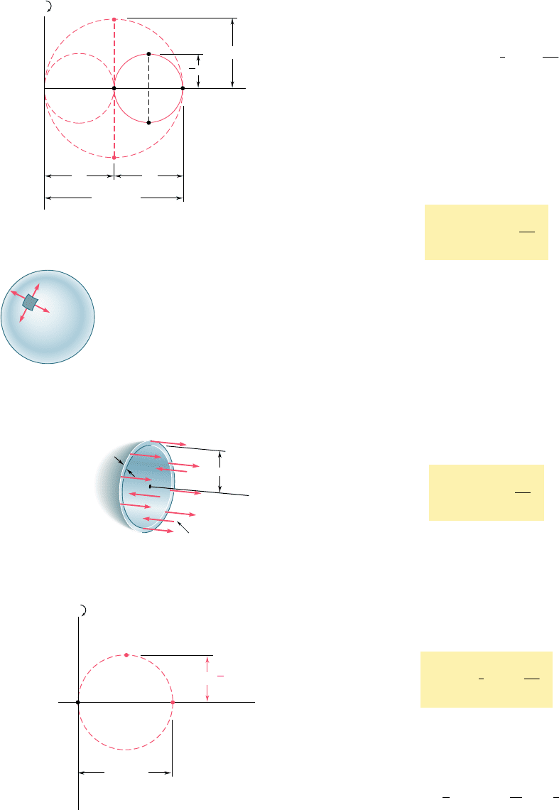
Drawing Mohr’s circle through the points A and B that corre-
spond respectively to the principal stresses s
1
and s
2
(Fig. 7.50), and
recalling that the maximum in-plane shearing stress is equal to the
radius of this circle, we have
t
max 1in plane2
5
1
2
s
2
5
p
r
4t
(7.33)
This stress corresponds to points D and E and is exerted on an ele-
ment obtained by rotating the original element of Fig. 7.47 through
458 within the plane tangent to the surface of the vessel. The maxi-
mum shearing stress in the wall of the vessel, however, is larger. It
is equal to the radius of the circle of diameter OA and corresponds
to a rotation of 458 about a longitudinal axis and out of the plane of
stress.† We have
t
max
5 s
2
5
p
r
2t
(7.34)
We now consider a spherical vessel of inner radius r and wall
thickness t, containing a fluid under a gage pressure p. For reasons
of symmetry, the stresses exerted on the four faces of a small element
of wall must be equal (Fig. 7.51). We have
s
1
5
s
2
(7.35)
To determine the value of the stress, we pass a section through the
center C of the vessel and consider the free body consisting of the
portion of the vessel and its contents located to the left of the section
(Fig. 7.52). The equation of equilibrium for this free body is the
same as for the free body of Fig. 7.49. We thus conclude that, for a
spherical vessel,
s
1
5 s
2
5
p
r
2t
(7.36)
Since the principal stresses s
1
and s
2
are equal, Mohr’s circle for
transformations of stress within the plane tangent to the surface of the
vessel reduces to a point (Fig. 7.53); we conclude that the in-plane
normal stress is constant and that the in-plane maximum shearing stress
is zero. The maximum shearing stress in the wall of the vessel, however,
is not zero; it is equal to the radius of the circle of diameter OA and
corresponds to a rotation of 458 out of the plane of stress. We have
t
max
5
1
2
s
1
5
p
r
4t
(7.37)
B
E
A
2
O
12
2
2
2
D'
D
E'
1
2
max
2
Fig. 7.50 Mohr’s circle for element of
cylindrical pressure vessel.
1
2
1
2
1
Fig. 7.51 Pressurized
spherical vessel.
2
r
x
p dA
dA
t
C
Fig. 7.52 Free body to
determine wall stress.
B
A
max
1
O
1
2
D'
1
2
Fig. 7.53 Mohr’s circle for element
of spherical pressure vessel.
†It should be observed that, while the third principal stress is zero on the outer surface of
the vessel, it is equal to 2p on the inner surface, and is represented by a point C(2p, 0)
on a Mohr-circle diagram. Thus, close to the inside surface of the vessel, the maximum
shearing stress is equal to the radius of a circle of diameter CA, and we have
t
max
5
1
2
1s
1
1 p25
p
r
2
t
a
1 1
t
r
b
For a thin-walled vessel, however, the term t/r is small, and we can neglect the variation
of t
max
across the wall section. This remark also applies to spherical pressure vessels.
bee80288_ch07_436-511.indd Page 480 10/30/10 1:42:04 AM user-f499bee80288_ch07_436-511.indd Page 480 10/30/10 1:42:04 AM user-f499 /Users/user-f499/Desktop/Temp Work/Don't Delete Job/MHDQ251:Beer:201/ch07/Users/user-f499/Desktop/Temp Work/Don't Delete Job/MHDQ251:Beer:201/ch07
Apago PDF Enhancer
481
SAMPLE PROBLEM 7.5
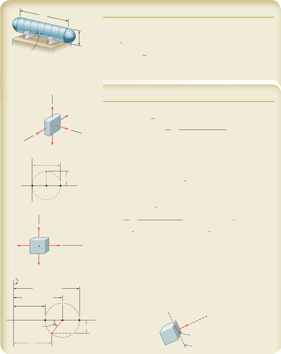
A compressed-air tank is supported by two cradles as shown; one of the cra-
dles is designed so that it does not exert any longitudinal force on the tank.
The cylindrical body of the tank has a 30-in. outer diameter and is fabricated
from a
3
8
-in. steel plate by butt welding along a helix that forms an angle of
258 with a transverse plane. The end caps are spherical and have a uniform
wall thickness of
5
16
in. For an internal gage pressure of 180 psi, determine
(a) the normal stress and the maximum shearing stress in the spherical caps.
(b) the stresses in directions perpendicular and parallel to the helical weld.
SOLUTION
a. Spherical Cap. Using Eq. (7.36), we write
p
5 180
p
si, t 5
5
16
in. 5 0.3125 in., r 5 15 2 0.3125 5 14.688 in.
s
1
5 s
2
5
p
r
2
t
5
1180 psi2114.688 in.
2
210.3125 in.2
s 5 4230 psib
We note that for stresses in a plane tangent to the cap, Mohr’s circle reduces
to a point (A, B) on the horizontal axis and that all in-plane shearing stresses
are zero. On the surface of the cap the third principal stress is zero and cor-
responds to point O. On a Mohr’s circle of diameter AO, point D9 represents
the maximum shearing stress; it occurs on planes at 458 to the plane tangent
to the cap.
t
max
5
1
2
14230 psi2 t
max
5 2115 psi
b
b. Cylindrical Body of the Tank. We first determine the hoop stress
s
1
and the longitudinal stress s
2
. Using Eqs. (7.30) and (7.32), we write
p
5 180
p
si, t 5
3
8
in. 5 0.375 in., r 5 15 2 0.375 5 14.625 in.
s
1
5
p
r
t
5
1
180 psi
21
14.625 in.
2
0
.
375 in
.
5 7020 psis
2
5
1
2
s
1
5 3510 psi
s
ave
5
1
2
1s
1
1 s
2
25 5265 psiR 5
1
2
1s
1
2 s
2
25 1755 psi
Stresses at the Weld. Noting that both the hoop stress and the longi-
tudinal stress are principal stresses, we draw Mohr’s circle as shown.
An element having a face parallel to the weld is obtained by rotating the
face perpendicular to the axis Ob counterclockwise through 258. Therefore, on
Mohr’s circle we locate the point X9 corresponding to the stress components
on the weld by rotating radius CB counterclockwise through 2u 5 508.
s
w
5 s
ave
2 R cos 50° 5 5265 2 1755 cos 50° s
w
514140 psib
t
w
5 R sin 50° 5 1755 sin 50° t
w
5
1344 psib
Since X9 is below the horizontal axis, t
w
tends to rotate the element
counterclockwise.
8 ft
30 in.
25°
1
2
0
a
b
1
max
2
4230 psi
C
A, B
O
D'
b
1
1
2
2
3510 psi
7020 psi
a
O
1
7020 psi
ave
5265 psi
2
w
3510 psi
1755 psi
X'
2 50°
AC
BO
R
R
w
x'
w
4140 psi
w
1344 psi
Weld
bee80288_ch07_436-511.indd Page 481 11/17/10 11:11:11 PM user-f499bee80288_ch07_436-511.indd Page 481 11/17/10 11:11:11 PM user-f499 /Users/user-f499/Desktop/Temp Work/Don't Delete Job/MHDQ251:Beer:201/ch07/Users/user-f499/Desktop/Temp Work/Don't Delete Job/MHDQ251:Beer:201/ch07
Apago PDF Enhancer
PROBLEMS
482
7.98 A spherical gas container made of steel has a 5-m outer diameter
and a wall thickness of 6 mm. Knowing that the internal pressure
is 350 kPa, determine the maximum normal stress and the maxi-
mum shearing stress in the container.
7.99 The maximum gage pressure is known to be 8 MPa in a spherical
steel pressure vessel having a 250-mm outer diameter and a 6-mm
wall thickness. Knowing that the ultimate stress in the steel used
is s
U
5 400 MPa, determine the factor of safety with respect to
tensile failure.
7.100 A basketball has a 9.5-in. outer diameter and a 0.125-in. wall thick-
ness. Determine the normal stress in the wall when the basketball
is inflated to a 9-psi gage pressure.
7.101 A spherical pressure vessel of 900-mm outer diameter is to be
fabricated from a steel having an ultimate stress s
U
5 400 MPa.
Knowing that a factor of safety of 4.0 is desired and that the gage
pressure can reach 3.5 MPa, determine the smallest wall thickness
that should be used.
7.102 A spherical pressure vessel has an outer diameter of 10 ft and a
wall thickness of 0.5 in. Knowing that for the steel used s
all
5
12 ksi, E 5 29 3 10
6
psi, and n 5 0.29, determine (a) the allowable
gage pressure, (b) the corresponding increase in the diameter of
the vessel.
7.103 A spherical gas container having an outer diameter of 5 m and a
wall thickness of 22 mm is made of steel for which E 5 200 GPa
and n 5 0.29. Knowing that the gage pressure in the container is
increased from zero to 1.7 MPa, determine (a) the maximum nor-
mal stress in the container, (b) the corresponding increase in the
diameter of the container.
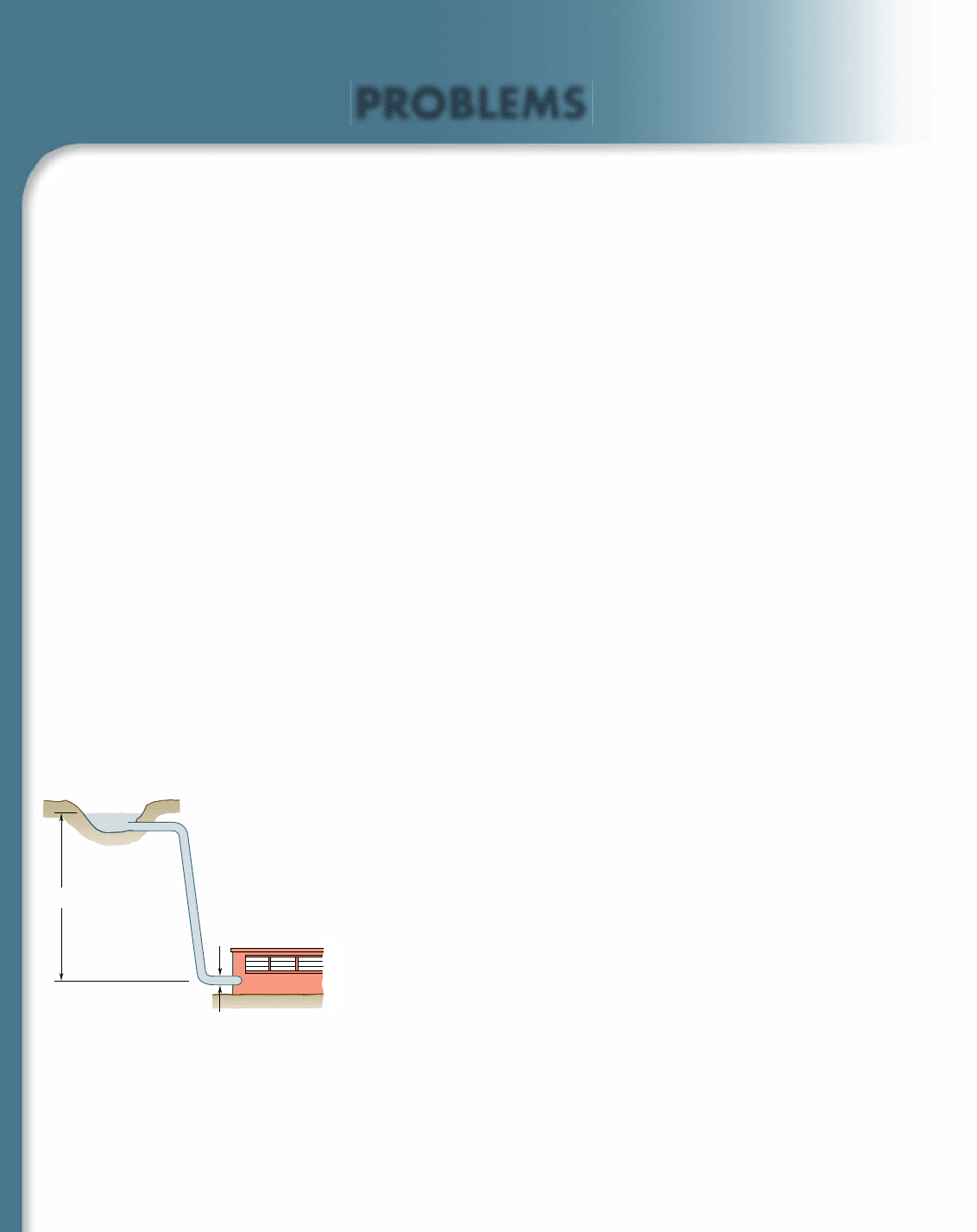
7.104 A steel penstock has a 750-mm outer diameter, a 12-mm wall thick-
ness, and connects a reservoir at A with a generating station at B.
Knowing that the density of water is 1000 kg/m
3
, determine the
maximum normal stress and the maximum shearing stress in the
penstock under static conditions.
7.105 A steel penstock has a 750-mm outer diameter and connects a
reservoir at A with a generating station at B. Knowing that the
density of water is 1000 kg/m
3
and that the allowable normal stress
in the steel is 85 MPa, determine the smallest thickness that can
be used for the penstock.
7.106 The bulk storage tank shown in Photo 7.3 has an outer diameter
of 3.3 m and a wall thickness of 18 mm. At a time when the internal
pressure of the tank is 1.5 MPa, determine the maximum normal
stress and the maximum shearing stress in the tank.
A
B
750 mm
300 m
Fig. P7.104 and P7.105
bee80288_ch07_436-511.indd Page 482 10/30/10 1:42:29 AM user-f499bee80288_ch07_436-511.indd Page 482 10/30/10 1:42:29 AM user-f499 /Users/user-f499/Desktop/Temp Work/Don't Delete Job/MHDQ251:Beer:201/ch07/Users/user-f499/Desktop/Temp Work/Don't Delete Job/MHDQ251:Beer:201/ch07
Apago PDF Enhancer
483
Problems
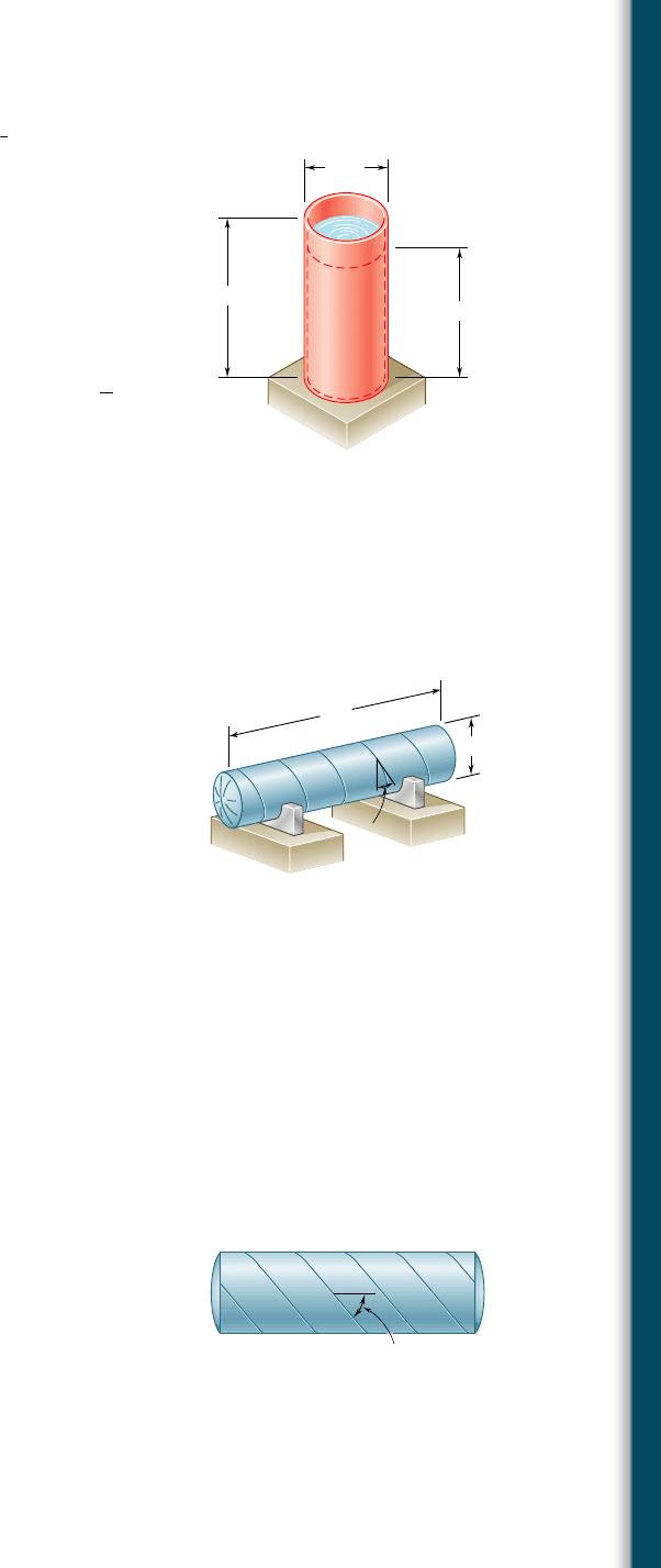
7.107 Determine the largest internal pressure that can be applied to a
cylindrical tank of 5.5-ft outer diameter and
5
8
-in. wall thickness if
the ultimate normal stress of the steel used is 65 ksi and a factor
of safety of 5.0 is desired.
7.108 A cylindrical storage tank contains liquefied propane under a pres-
sure of 1.5 MPa at a temperature of 388C. Knowing that the tank
has an outer diameter of 320 mm and a wall thickness of 3 mm,
determine the maximum normal stress and the maximum shearing
stress in the tank.
7.109 The unpressurized cylindrical storage tank shown has a
3
16
-in. wall
thickness and is made of steel having a 60-ksi ultimate strength in
tension. Determine the maximum height h to which it can be filled
with water if a factor of safety of 4.0 is desired. (Specific weight
of water 5 62.4 lb/ft
3
.)
7.110 For the storage tank of Prob. 7.109, determine the maximum nor-
mal stress and the maximum shearing stress in the cylindrical wall
when the tank is filled to capacity (h 5 48 ft).
7.111 A standard-weight steel pipe of 12-in. nominal diameter carries
water under a pressure of 400 psi. (a) Knowing that the outside
diameter is 12.75 in. and the wall thickness is 0.375 in., determine
the maximum tensile stress in the pipe. (b) Solve part a, assuming
an extra-strong pipe is used, of 12.75-in. outside diameter and
0.5-in. wall thickness.
7.112 The pressure tank shown has a 8-mm wall thickness and butt-welded
seams forming an angle b 5 208 with a transverse plane. For a gage
pressure of 600 kPa, determine, (a) the normal stress perpendicular
to the weld, (b) the shearing stress parallel to the weld.
7.113 For the tank of Prob. 7.112, determine the largest allowable gage
pressure, knowing that the allowable normal stress perpendicular
to the weld is 120 MPa and the allowable shearing stress parallel
to the weld is 80 MPa.
7.114 For the tank of Prob. 7.112, determine the range of values of b
that can be used if the shearing stress parallel to the weld is not
to exceed 12 MPa when the gage pressure is 600 kPa.
7.115 The steel pressure tank shown has a 750-mm inner diameter and
a 9-mm wall thickness. Knowing that the butt-welded seams form
an angle b 5 508 with the longitudinal axis of the tank and that
the gage pressure in the tank is 1.5 MPa, determine, (a) the normal
stress perpendicular to the weld, (b) the shearing stress parallel to
the weld.
7.116 The pressurized tank shown was fabricated by welding strips of
plate along a helix forming an angle b with a transverse plane.
Determine the largest value of b that can be used if the normal
stress perpendicular to the weld is not to be larger than 85 percent
of the maximum stress in the tank.
25 ft
48 ft
h
Fig. P7.109
3 m
1.6 m
Fig. P7.112
Fig. P7.115 and P7.116
bee80288_ch07_436-511.indd Page 483 10/30/10 1:42:33 AM user-f499bee80288_ch07_436-511.indd Page 483 10/30/10 1:42:33 AM user-f499 /Users/user-f499/Desktop/Temp Work/Don't Delete Job/MHDQ251:Beer:201/ch07/Users/user-f499/Desktop/Temp Work/Don't Delete Job/MHDQ251:Beer:201/ch07
Apago PDF Enhancer
484
Transformations of Stress and Strain
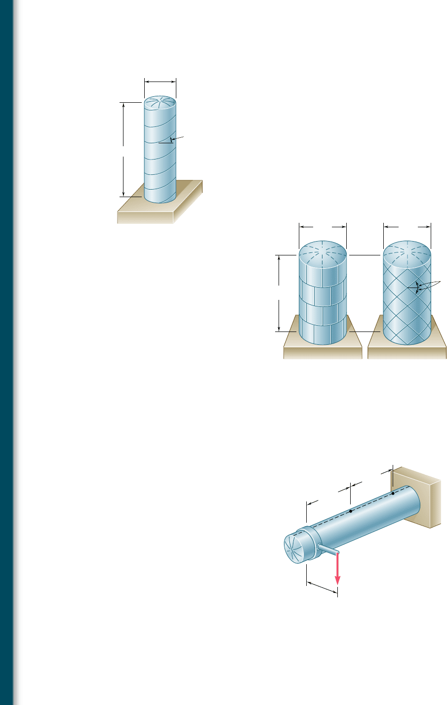
7.117 The cylindrical portion of the compressed-air tank shown is fabri-
cated of 0.25-in.-thick plate welded along a helix forming an angle
b 5 308 with the horizontal. Knowing that the allowable stress
normal to the weld is 10.5 ksi, determine the largest gage pressure
that can be used in the tank.
7.118 For the compressed-air tank of Prob. 7.117, determine the gage
pressure that will cause a shearing stress parallel to the weld of
4 ksi.
7.119 Square plates, each of 0.5-in. thickness, can be bent and welded
together in either of the two ways shown to form the cylindrical
portion of a compressed-air tank. Knowing that the allowable nor-
mal stress perpendicular to the weld is 12 ksi, determine the largest
allowable gage pressure in each case.
20 in.
60 in.
Fig. P7.117
20 ft
12 ft 12 ft
45
(a)(b)
Fig. P7.119
7.120 The compressed-air tank AB has an inner diameter of 450 mm and
a uniform wall thickness of 6 mm. Knowing that the gage pressure
inside the tank is 1.2 MPa, determine the maximum normal stress
and the maximum in-plane shearing stress at point a on the top of
the tank.
7.121 For the compressed-air tank and loading of Prob. 7.120, determine
the maximum normal stress and the maximum in-plane shearing
stress at point b on the top of the tank.
D
A
B
a
b
750 mm
500 mm
750 mm
5 kN
Fig. P7.120
bee80288_ch07_436-511.indd Page 484 10/30/10 1:42:40 AM user-f499bee80288_ch07_436-511.indd Page 484 10/30/10 1:42:40 AM user-f499 /Users/user-f499/Desktop/Temp Work/Don't Delete Job/MHDQ251:Beer:201/ch07/Users/user-f499/Desktop/Temp Work/Don't Delete Job/MHDQ251:Beer:201/ch07
Apago PDF Enhancer
485
Problems
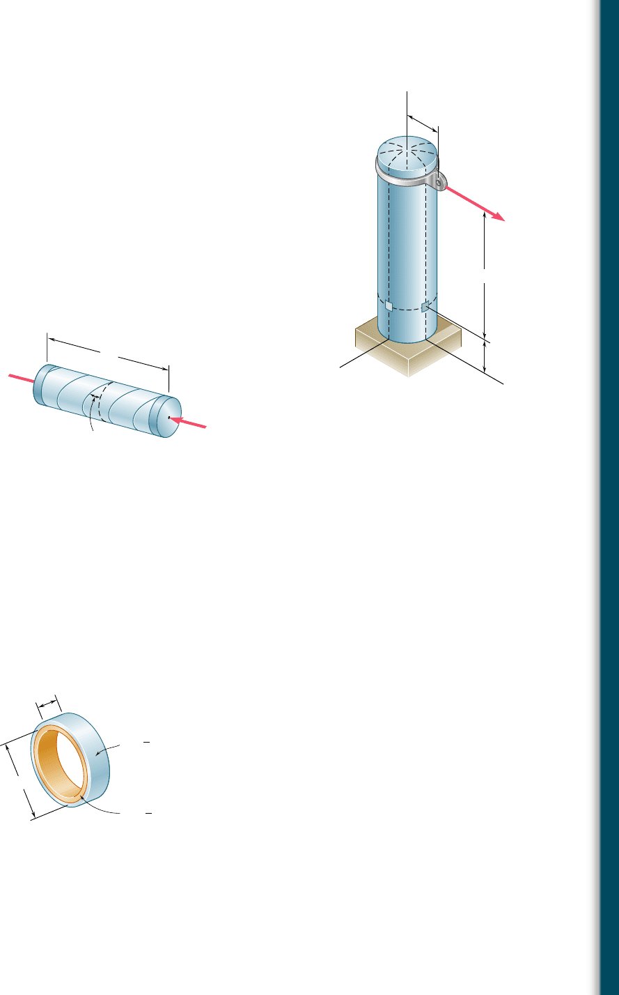
7.122 The compressed-air tank AB has a 250-mm outside diameter and
an 8-mm wall thickness. It is fitted with a collar by which a 40-kN
force P is applied at B in the horizontal direction. Knowing that
the gage pressure inside the tank is 5 MPa, determine the maxi-
mum normal stress and the maximum shearing stress at point K.
7.123 In Prob. 7.122, determine the maximum normal stress and the
maximum shearing stress at point L.
7.124 A pressure vessel of 10-in. inner diameter and 0.25-in. wall thick-
ness is fabricated from a 4-ft section of spirally-welded pipe AB
and is equipped with two rigid end plates. The gage pressure inside
the vessel is 300 psi and 10-kip centric axial forces P and P9 are
applied to the end plates. Determine (a) the normal stress perpen-
dicular to the weld, (b) the shearing stress parallel to the weld.
7.125 Solve Prob. 7.124, assuming that the magnitude P of the two forces
is increased to 30 kips.
7.126 A brass ring of 5-in. outer diameter and 0.25-in. thickness fits
exactly inside a steel ring of 5-in. inner diameter and 0.125-in.
thickness when the temperature of both rings is 508F. Knowing
that the temperature of both rings is then raised to 1258F, deter-
mine (a) the tensile stress in the steel ring, (b) the corresponding
pressure exerted by the brass ring on the steel ring.
600 mm
150 mm
A
B
150 mm
P
x
y
z
KL
Fig. P7.122
4 ft
P
P'
35
B
A
Fig. P7.124
7.127 Solve Prob. 7.126, assuming that the brass ring is 0.125 in. thick
and the steel ring is 0.25 in. thick.
STEEL
t
s
E
s
29 10
6
psi
s
6.5 10
–6
/F
in.
1
8
s
BRASS
t
b
E
b
15 10
6
psi
s
11.6 10
–
6
/F
in.
1
4
b
1.5 in.
5 in.
Fig. P7.126
bee80288_ch07_436-511.indd Page 485 10/30/10 1:42:47 AM user-f499bee80288_ch07_436-511.indd Page 485 10/30/10 1:42:47 AM user-f499 /Users/user-f499/Desktop/Temp Work/Don't Delete Job/MHDQ251:Beer:201/ch07/Users/user-f499/Desktop/Temp Work/Don't Delete Job/MHDQ251:Beer:201/ch07
Apago PDF Enhancer
486
Transformations of Stress and Strain
*7.10 TRANSFORMATION OF PLANE STRAIN
Transformations of strain under a rotation of the coordinate axes will
now be considered. Our analysis will first be limited to states of plane
strain, i.e., to situations where the deformations of the material take
place within parallel planes, and are the same in each of these planes.
If the z axis is chosen perpendicular to the planes in which the defor-
mations take place, we have P
z
5 g
zx
5 g
zy
5 0, and the only remaining
strain components are P
x
, P
y
, and g
xy
. Such a situation occurs in a plate
subjected along its edges to uniformly distributed loads and restrained
from expanding or contracting laterally by smooth, rigid, and fixed sup-
ports (Fig. 7.54). It would also be found in a bar of infinite length
subjected on its sides to uniformly distributed loads since, by reason of
symmetry, the elements located in a given transverse plane cannot
move out of that plane. This idealized model shows that, in the actual
case of a long bar subjected to uniformly distributed transverse loads
(Fig. 7.55), a state of plane strain exists in any given transverse section
that is not located too close to either end of the bar.†
†It should be observed that a state of plane strain and a state of plane stress (cf. Sec. 7.1)
do not occur simultaneously, except for ideal materials with a Poisson ratio equal to zero.
The constraints placed on the elements of the plate of Fig. 7.54 and of the bar of Fig. 7.55
result in a stress s
z
different from zero. On the other hand, in the case of the plate of Fig.
7.3, the absence of any lateral restraint results in s
z
5 0 and P
z
Z 0.
Fixed support
Fixed support
y
z
x
Fig. 7.54 Plane strain example: laterally
restrained plate.
y
z
x
Fig. 7.55 Plane strain example: bar
of infinite length.
Q
Q
s
s
s (1 )
y
)
x
y
x
O
y
x
O
s (1
2
xy
2
xy
Fig. 7.56 Plane strain element deformation.
Q
Q
s
s
s (1 )
y'
s (1 )
x'
y
x
O
x
O
x'y'
2
x'y'
2
y
'
y'
x
'
x'
Fig. 7.57 Transformation of plane strain
element.
Let us assume that a state of plane strain exists at point Q (with
P
z
5 g
zx
5 g
zy
5 0), and that it is defined by the strain components
P
z
, P
y
, and g
xy
associated with the x and y axes. As we know from
Secs. 2.12 and 2.14, this means that a square element of center Q,
with sides of length Ds respectively parallel to the x and y axes, is
deformed into a parallelogram with sides of length respectively equal
to Ds (1 1 P
x
) and Ds (1 1 P
y
), forming angles of
p
2
2 g
x
y
and
p
2
1 g
x
y
with each other (Fig. 7.56). We recall that, as a result of the defor-
mations of the other elements located in the xy plane, the element
considered may also undergo a rigid-body motion, but such a motion
is irrelevant to the determination of the strains at point Q and will
be ignored in this analysis. Our purpose is to determine in terms of
P
x
, P
y
, g
xy
, and u the strain components P
x9
, P
y9
, and g
x9y9
associated
with the frame of reference x9y9 obtained by rotating the x and y
axes through the angle u. As shown in Fig. 7.57, these new strain
bee80288_ch07_436-511.indd Page 486 10/30/10 3:32:34 PM user-f499bee80288_ch07_436-511.indd Page 486 10/30/10 3:32:34 PM user-f499/Users/user-f499/Desktop/Temp Work/Don't Delete Job/MHDQ251:Beer:201/ch07/Users/user-f499/Desktop/Temp Work/Don't Delete Job/MHDQ251:Beer:201/ch
