Beer F.P., Johnston E.R., DeWolf J.T., Mazurek D.F. Mechanics of Materials
Подождите немного. Документ загружается.

Apago PDF Enhancer
507
REVIEW PROBLEMS
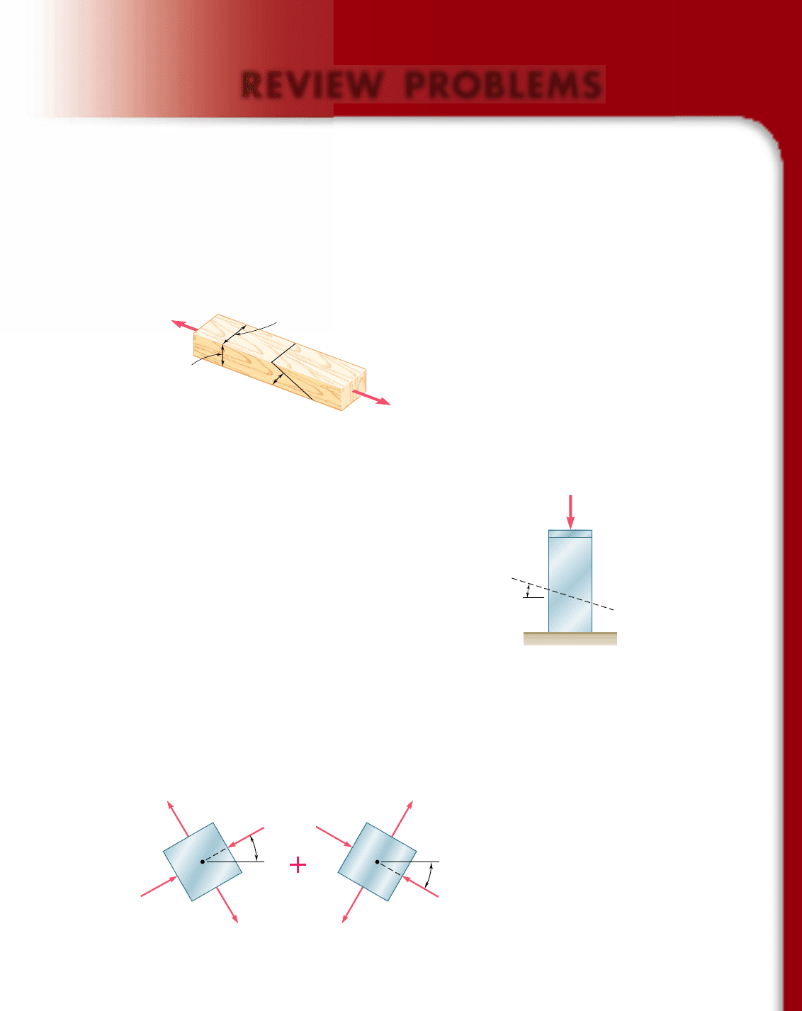
7.158 Two wooden members of 80 3 120-mm uniform rectangular cross
section are joined by the simple glued scarf splice shown. Knowing
that b 5 228 and that the maximum allowable stresses in the joint
are, respectively, 400 kPa in tension (perpendicular to the splice)
and 600 kPa in shear (parallel to the splice), determine the largest
centric load P that can be applied.
P'
P
80 mm
120 mm
Fig. P7.158 and P7.159
P
a
a
Fig. P7.160
7.159 Two wooden members of 80 3 120-mm uniform rectangular cross
section are joined by the simple glued scarf splice shown. Knowing
that b 5 258 and that centric loads of magnitude P 5 10 kN are
applied to the members as shown, determine (a) the in-plane
shearing stress parallel to the splice, (b) the normal stress perpen-
dicular to the splice.
7.16 0 The centric force P is applied to a short post as shown. Knowing
that the stresses on plane a-a are s 5 215 ksi and t 5 5 ksi,
determine (a) the angle b that plane a-a forms with the horizontal,
(b) the maximum compressive stress in the post.
7.161 Determine the principal planes and the principal stresses for the
state of plane stress resulting from the superposition of the two
states of stress shown.
0
0
0
0
30
30
Fig. P7.161
bee80288_ch07_436-511.indd Page 507 10/30/10 3:35:52 PM user-f499bee80288_ch07_436-511.indd Page 507 10/30/10 3:35:52 PM user-f499/Users/user-f499/Desktop/Temp Work/Don't Delete Job/MHDQ251:Beer:201/ch07/Users/user-f499/Desktop/Temp Work/Don't Delete Job/MHDQ251:Beer:201/ch
Apago PDF Enhancer
508
Transformations of Stress and Strain
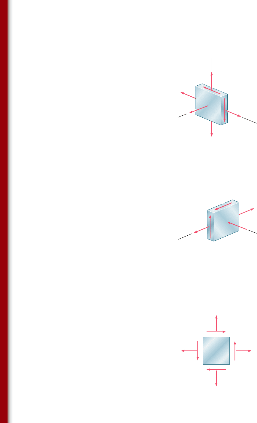
7.163 For the state of stress shown, determine the maximum shearing
stress when (a) t
yz
5 17.5 ksi, (b) t
yz
5 8 ksi, (c) t
yz
5 0.
z
x
τ
yz
3 ksi12 ksi
y
Fig. P7.163
xy
14 ksi
24 ksi
Fig. P7.164
7.16 4 The state of plane stress shown occurs in a machine component
made of a steel with s
Y
5 30 ksi. Using the maximum-distortion-
energy criterion, determine whether yield will occur when (a) t
xy
5
6 ksi, (b) t
xy
5 12 ksi, (c) t
xy
5 14 ksi. If yield does not occur,
determine the corresponding factor of safety.
7.162 For the state of stress shown, determine the maximum shearing
stress when (a) s
z
5 124 MPa, (b) s
z
5 224 MPa, (c) s
z
5 0.
z
σ
z
36 MPa
y
x
42 MPa
12 MPa
Fig. P7.162
bee80288_ch07_436-511.indd Page 508 10/30/10 3:36:01 PM user-f499bee80288_ch07_436-511.indd Page 508 10/30/10 3:36:01 PM user-f499/Users/user-f499/Desktop/Temp Work/Don't Delete Job/MHDQ251:Beer:201/ch07/Users/user-f499/Desktop/Temp Work/Don't Delete Job/MHDQ251:Beer:201/ch
Apago PDF Enhancer
509
Review Problems
T
Fig. P7.165 and
P7.166
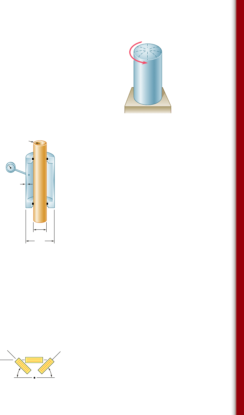
7.165 A torque of magnitude T 5 12 kN ? m is applied to the end of a
tank containing compressed air under a pressure of 8 MPa. Know-
ing that the tank has a 180-mm inner diameter and a 12-mm wall
thickness, determine the maximum normal stress and the maxi-
mum shearing stress in the tank.
7.166 The tank shown has a 180-mm inner diameter and a 12-mm wall
thickness. Knowing that the tank contains compressed air under a
pressure of 8 MPa, determine the magnitude T of the applied
torque for which the maximum normal stress is 75 MPa.
7.167 The brass pipe AD is fitted with a jacket used to apply a hydrostatic
pressure of 500 psi to portion BC of the pipe. Knowing that the
pressure inside the pipe is 100 psi, determine the maximum normal
stress in the pipe.
7.168 For the assembly of Prob. 7.167, determine the normal stress in
the jacket (a) in a direction perpendicular to the longitudinal axis
of the jacket, (b) in a direction parallel to that axis.
7.169 Determine the largest in-plane normal strain, knowing that the
following strains have been obtained by the use of the rosette
shown:
P
1
5250 3 10
2
6
in./in. P
2
51360 3 10
2
6
in./in.
P
3
51315 3 10
2
6
in./in.
D
2 in.
4 in.
A
B
C
0.12 in.
0.15 in.
Fig. P7.167
x
45 45
2
3
1
Fig. P7.169
bee80288_ch07_436-511.indd Page 509 10/30/10 3:36:12 PM user-f499bee80288_ch07_436-511.indd Page 509 10/30/10 3:36:12 PM user-f499/Users/user-f499/Desktop/Temp Work/Don't Delete Job/MHDQ251:Beer:201/ch07/Users/user-f499/Desktop/Temp Work/Don't Delete Job/MHDQ251:Beer:201/ch
Apago PDF Enhancer
510
COMPUTER PROBLEMS
The following problems are to be solved with a computer.
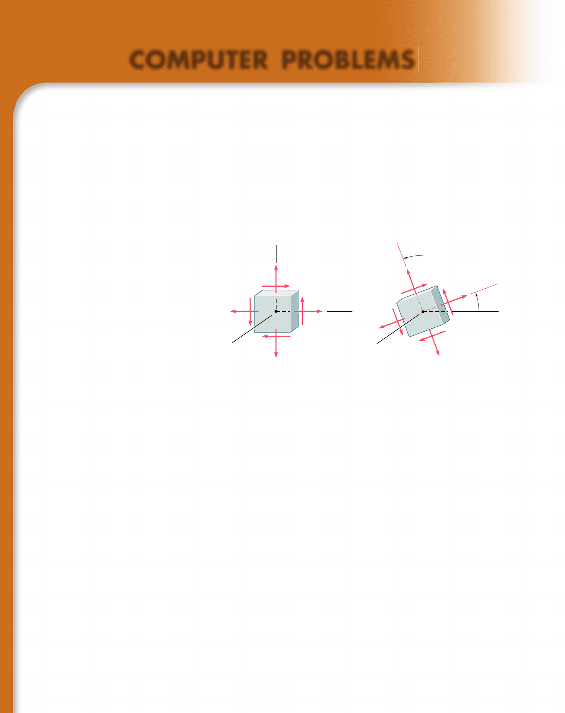
7.C1 A state of plane stress is defined by the stress components s
x
, s
y
,
and t
xy
associated with the element shown in Fig. P7.C1a. (a) Write a com-
puter program that can be used to calculate the stress components s
x9
, s
y9
,
and t
x9y9
associated with the element after it has rotated through an angle u
about the z axis (Fig. P.7C1b). (b) Use this program to solve Probs. 7.13
through 7.16.
xy
x'y'
y
y'
x
x'
Q
Q
z
xx
x
'
y
y'
z
y
(a)(b)
Fig. P7.C1
7.C2 A state of plane stress is defined by the stress components s
x
, s
y
,
and t
xy
associated with the element shown in Fig. P7.C1a. (a) Write a
computer program that can be used to calculate the principal axes, the
principal stresses, the maximum in-plane shearing stress, and the maxi-
mum shearing stress. (b) Use this program to solve Probs. 7.5, 7.9, 7.68,
and 7.69.
7.C3 (a) Write a computer program that, for a given state of plane stress
and a given yield strength of a ductile material, can be used to determine
whether the material will yield. The program should use both the maximum
shearing-strength criterion and the maximum-distortion-energy criterion. It
should also print the values of the principal stresses and, if the material does
not yield, calculate the factor of safety. (b) Use this program to solve Probs.
7.81, 7.82, and 7.164.
7.C4 (a) Write a computer program based on Mohr’s fracture criterion
for brittle materials that, for a given state of plane stress and given values
of the ultimate strength of the material in tension and compression, can be
used to determine whether rupture will occur. The program should also
print the values of the principal stresses. (b) Use this program to solve
Probs. 7.91 and 7.92 and to check the answers to Probs. 7.93 and 7.94.
bee80288_ch07_436-511.indd Page 510 10/30/10 3:36:18 PM user-f499bee80288_ch07_436-511.indd Page 510 10/30/10 3:36:18 PM user-f499/Users/user-f499/Desktop/Temp Work/Don't Delete Job/MHDQ251:Beer:201/ch07/Users/user-f499/Desktop/Temp Work/Don't Delete Job/MHDQ251:Beer:201/ch

Apago PDF Enhancer
511
Computer Problems
7.C5 A state of plane strain is defined by the strain components P
x
, P
y
,
and g
xy
associated with the x and y axes. (a) Write a computer program that
can be used to calculate the strain components P
x9
, P
y9
, and g
x9y9
associated
with the frame of reference x9y9 obtained by rotating the x and y axes
through an angle u. (b) Use this program to solve Probs. 7.129 and 7.131.
y
y'
x
'
x
Fig. P7.C5
7.C6 A state of strain is defined by the strain components P
x
, P
y
, and g
xy
associated with the x and y axes. (a) Write a computer program that can be
used to determine the orientation and magnitude of the principal strains,
the maximum in-plane shearing strain, and the maximum shearing strain.
(b) Use this program to solve Probs. 7.136 through 7.139.
7.C7 A state of plane strain is defined by the strain components P
x
, P
y
,
and g
xy
measured at a point. (a) Write a computer program that can be used
to determine the orientation and magnitude of the principal strains, the
maximum in-plane shearing strain, and the magnitude of the shearing strain.
(b) Use this program to solve Probs. 7.140 through 7.143.
7.C8 A rosette consisting of three gages forming, respectively, angles of
u
1
, u
2
, and u
3
with the x axis is attached to the free surface of a machine
component made of a material with a given Poisson’s ratio y. (a) Write a
computer program that, for given readings P
1
, P
2
, and P
3
of the gages, can
be used to calculate the strain components associated with the x and y axes
and to determine the orientation and magnitude of the three principal
strains, the maximum in-plane shearing strain, and the maximum shearing
strain. (b) Use this program to solve Probs. 7.144, 7.145, 7.146, and 7.169.
bee80288_ch07_436-511.indd Page 511 10/30/10 3:36:24 PM user-f499bee80288_ch07_436-511.indd Page 511 10/30/10 3:36:24 PM user-f499/Users/user-f499/Desktop/Temp Work/Don't Delete Job/MHDQ251:Beer:201/ch07/Users/user-f499/Desktop/Temp Work/Don't Delete Job/MHDQ251:Beer:201/ch

Apago PDF Enhancer
Due to gravity and wind load, the post
supporting the sign shown is subjected
simultaneously to compression, bending,
and torsion. In this chapter you will
learn to determine the stresses created
by such combined loadings in structures
and machine components.
512
bee80288_ch08_512-547.indd Page 512 10/30/10 4:53:33 PM user-f499bee80288_ch08_512-547.indd Page 512 10/30/10 4:53:33 PM user-f499/Users/user-f499/Desktop/Temp Work/Don't Delete Job/MHDQ251:Beer:201/ch08/Users/user-f499/Desktop/Temp Work/Don't Delete Job/MHDQ251:Beer:201/ch

Apago PDF Enhancer
513
Principal Stresses under a
Given Loading
8
CHAPTER
bee80288_ch08_512-547.indd Page 513 10/30/10 4:56:26 PM user-f499bee80288_ch08_512-547.indd Page 513 10/30/10 4:56:26 PM user-f499/Users/user-f499/Desktop/Temp Work/Don't Delete Job/MHDQ251:Beer:201/ch08/Users/user-f499/Desktop/Temp Work/Don't Delete Job/MHDQ251:Beer:201/ch
Apago PDF Enhancer
514
Chapter 8 Principal Stresses
under a Given Loading
*8.1 Introduction
*8.2 Principal Stresses in a Beam
*8.3 Design of Transmission Shafts
*8.4 Stresses under Combined
Loadings
*8.1 INTRODUCTION
In the first part of this chapter, you will apply to the design of beams
and shafts the knowledge that you acquired in Chap. 7 on the trans-
formation of stresses. In the second part of the chapter, you will learn
how to determine the principal stresses in structural members and
machine elements under given loading conditions.
In Chap. 5 you learned to calculate the maximum normal stress
s
m
occurring in a beam under a transverse loading (Fig. 8.1a) and
check whether this value exceeded the allowable stress s
all
for the
given material. If it did, the design of the beam was not acceptable.
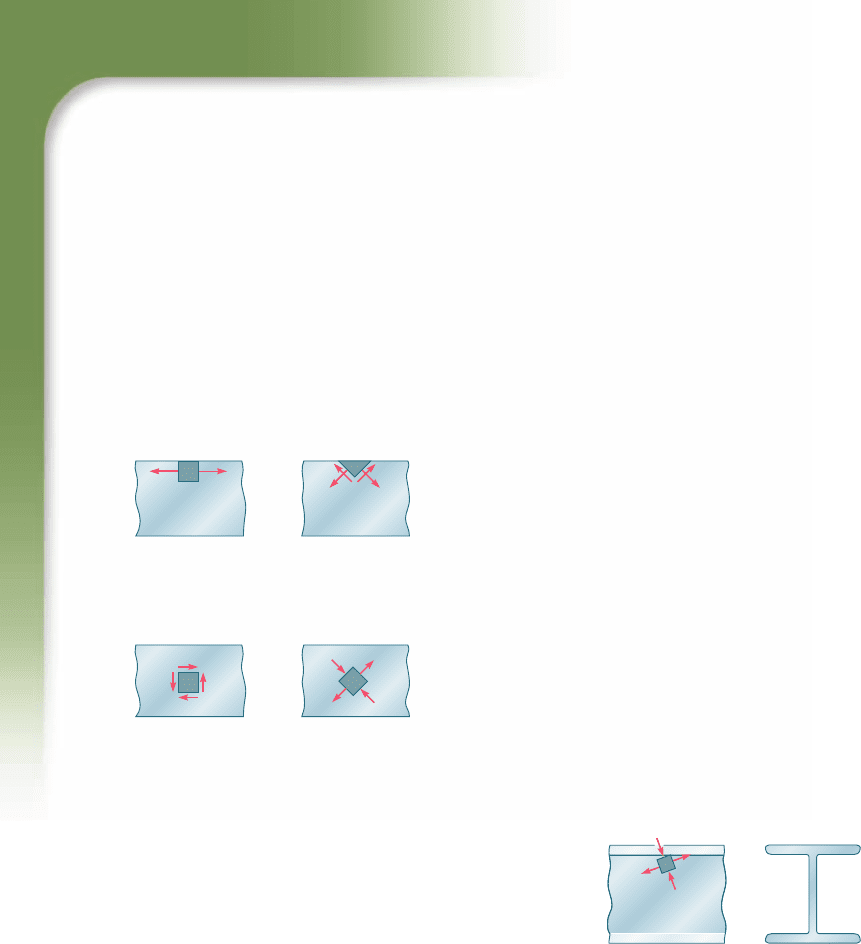
While the danger for a brittle material is actually to fail in tension,
the danger for a ductile material is to fail in shear (Fig. 8.1b). The
fact that s
m
. s
all
indicates that |M|
max
is too large for the cross sec-
tion selected, but does not provide any information on the actual
mechanism of failure. Similarly, the fact that t
m
. t
all
simply indi-
cates that |V|
max
is too large for the cross section selected. While the
danger for a ductile material is actually to fail in shear (Fig. 8.2a),
the danger for a brittle material is to fail in tension under the prin-
cipal stresses (Fig. 8.2b). The distribution of the principal stresses in
a beam will be discussed in Sec. 8.2.
Depending upon the shape of the cross section of the beam and
the value of the shear V in the critical section where |M| 5 |M|
max
, it
may happen that the largest value of the normal stress will not occur
at the top or bottom of the section, but at some other point within the
section. As you will see in Sec. 8.2, a combination of large values of s
x
and t
xy
near the junction of the web and the flanges of a W-beam or
an S-beam can result in a value of the principal stress s
max
(Fig. 8.3)
that is larger than the value of s
m
on the surface of the beam.
Section 8.3 will be devoted to the design of transmission shafts
subjected to transverse loads as well as to torques. The effect of both
the normal stresses due to bending and the shearing stresses due to
torsion will be taken into account.
In Sec. 8.4 you will learn to determine the stresses at a given
point K of a body of arbitrary shape subjected to a combined loading.
First, you will reduce the given loading to forces and couples in the
section containing K. Next, you will calculate the normal and shearing
stresses at K. Finally, using one of the methods for the transformation
of stresses that you learned in Chap. 7, you will determine the principal
planes, principal stresses, and maximum shearing stress at K.
m
max
m
'
(a)(b)
Fig. 8.1
m
'
'
(a)(b)
Fig. 8.2
max
Fig. 8.3 Principal stresses at the
junction of a flange and web in
an I-shaped beam.
bee80288_ch08_512-547.indd Page 514 10/30/10 4:56:45 PM user-f499bee80288_ch08_512-547.indd Page 514 10/30/10 4:56:45 PM user-f499/Users/user-f499/Desktop/Temp Work/Don't Delete Job/MHDQ251:Beer:201/ch08/Users/user-f499/Desktop/Temp Work/Don't Delete Job/MHDQ251:Beer:201/ch
Apago PDF Enhancer
515
8.2 Principal Stresses in a Beam
*8.2 PRINCIPAL STRESSES IN A BEAM
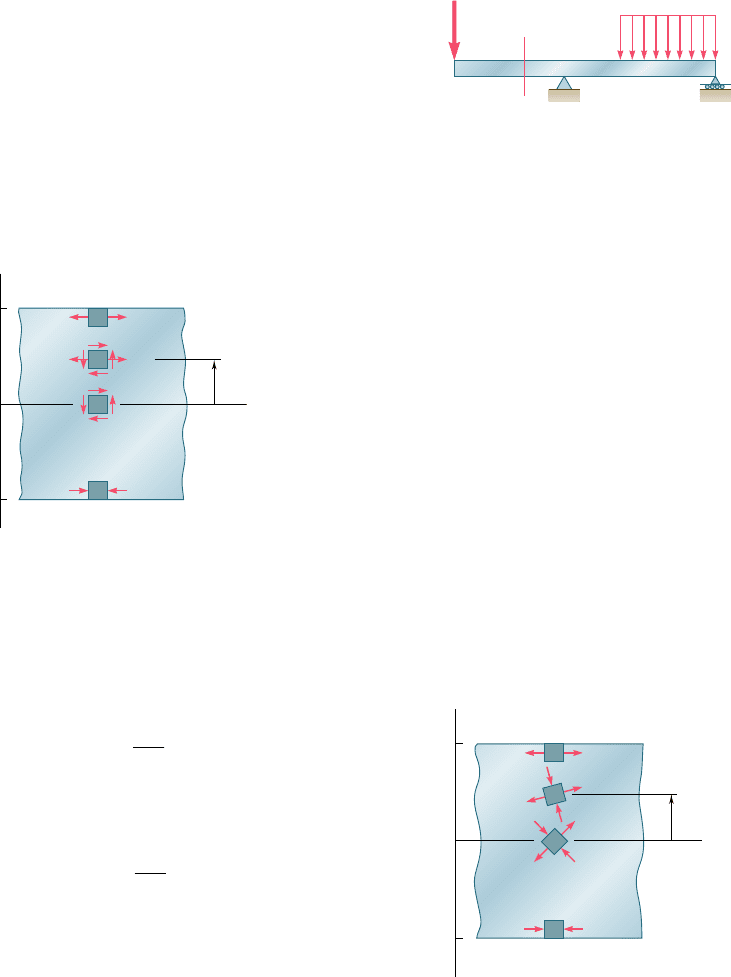
Consider a prismatic beam AB subjected to some arbitrary transverse
loading (Fig. 8.4). We denote by V and M, respectively, the shear
and bending moment in a section through a given point C. We recall
from Chaps. 5 and 6 that, within the elastic limit, the stresses exerted
on a small element with faces perpendicular, respectively, to the x
and y axes reduce to the normal stresses s
m
5 McyI if the element
is at the free surface of the beam, and to the shearing stresses t
m
5
VQyIt if the element is at the neutral surface (Fig. 8.5).
At any other point of the cross section, an element of material
is subjected simultaneously to the normal stresses
s
x
52
M
y
I
(8.1)
where y is the distance from the neutral surface and I the centroidal
moment of inertia of the section, and to the shearing stresses
t
xy
52
V
Q
I
t
(8.2)
where Q is the first moment about the neutral axis of the portion of
the cross-sectional area located above the point where the stresses are
computed, and t the width of the cross section at that point. Using
either of the methods of analysis presented in Chap. 7, we can obtain
the principal stresses at any point of the cross section (Fig. 8.6).
The following question now arises: Can the maximum normal
stress s
max
at some point within the cross section be larger than
the value of s
m
5 McyI computed at the surface of the beam? If
it can, then the determination of the largest normal stress in the
beam will involve a great deal more than the computation of |M|
max
and the use of Eq. (8.1). We can obtain an answer to this question
by investigating the distribution of the principal stresses in a narrow
B
w
A
C
D
P
Fig. 8.4 Transversely loaded prismatic
beam.
Fig. 8.5 Stress elements at
selected points of a beam.
m
m
m
m
m
xy
x
x
c
y
y
x
O
c
m
m
m
m
min
min
max
max
c
y
y
x
O
c
Fig. 8.6 Principal stresses at
selected points of a beam.
bee80288_ch08_512-547.indd Page 515 11/19/10 3:10:21 PM user-f499bee80288_ch08_512-547.indd Page 515 11/19/10 3:10:21 PM user-f499 /Users/user-f499/Desktop/Temp Work/Don't Delete Job/MHDQ251:Beer:201/ch08/Users/user-f499/Desktop/Temp Work/Don't Delete Job/MHDQ251:Beer:201/ch08
Apago PDF Enhancer
516
Principal Stresses under a Given Loading
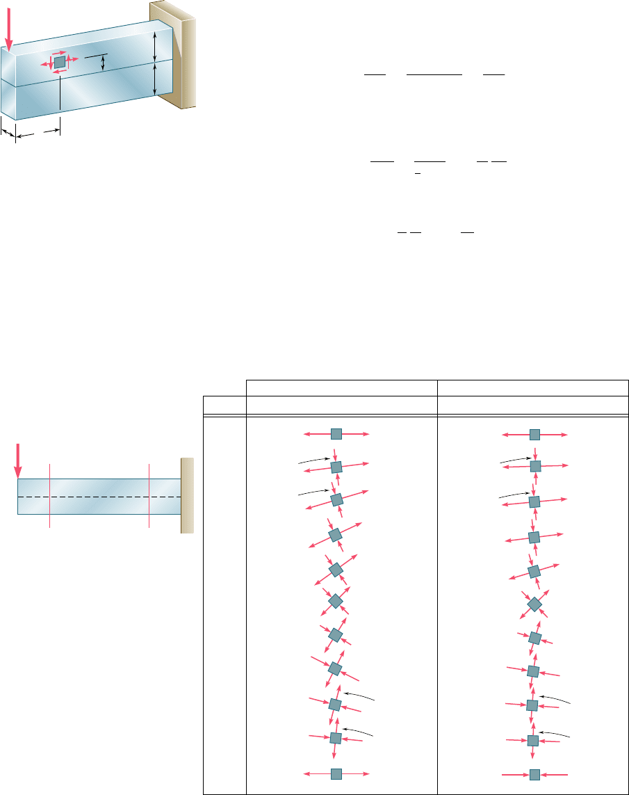
rectangular cantilever beam subjected to a concentrated load P at
its free end (Fig. 8.7). We recall from Sec. 6.5 that the normal and
shearing stresses at a distance x from the load P and a distance y
above the neutral surface are given, respectively, by Eq. (6.13) and
Eq. (6.12). Since the moment of inertia of the cross section is
I 5
bh
3
12
5
1bh212c2
2
12
5
Ac
2
3
where A is the cross-sectional area and c the half-depth of the beam,
we write
s
x
5
Px
y
I
5
Pxy
1
3
Ac
2
5 3
P
A
x
y
c
2
(8.3)
and
t
xy
5
3
2
P
A
a
1 2
y
2
c
2
b
(8.4)
Using the method of Sec. 7.3 or Sec. 7.4, the value of s
max
can
be determined at any point of the beam. Figure 8.8 shows the results
of the computation of the ratios s
max
ys
m
and s
min
ys
m
in two sections
of the beam, corresponding respectively to x 5 2c and x 5 8c. In
c
c
b
x
y
x
xy
P
Fig. 8.7 Narrow rectangular
cantilever beam supporting a single
concentrated load.
1.0
y/c
min
/
m
min
/
m
max
/
m
max
/
m
x 2c x 8c
0.8
0.6
0.4
0.2
0.2
0.4
0.6
0.8
1.0
0
0
0.010
0.040
0.090
0.160
0.360
0.490
0.640
0.810
1.000
0.250
1.000
0.810
0.640
0.490
0.360
0.160
0.090
0.040
0.010
0
0.250
0
0.001
0.003
0.007
0.017
0.217
0.407
0.603
0.801
1.000
0.063
1.000
0.801
0.603
0.407
0.217
0.017
0.007
0.003
0.001
0
0.063
y c
x 2cx 8c
y c
y 0
P
Fig. 8.8 Distribution of principal stresses in two transverse sections of a rectangular cantilever beam supporting a single
con centrated load.
bee80288_ch08_512-547.indd Page 516 10/30/10 4:56:59 PM user-f499bee80288_ch08_512-547.indd Page 516 10/30/10 4:56:59 PM user-f499/Users/user-f499/Desktop/Temp Work/Don't Delete Job/MHDQ251:Beer:201/ch08/Users/user-f499/Desktop/Temp Work/Don't Delete Job/MHDQ251:Beer:201/ch
