Beer F.P., Johnston E.R., DeWolf J.T., Mazurek D.F. Mechanics of Materials
Подождите немного. Документ загружается.

Apago PDF Enhancer
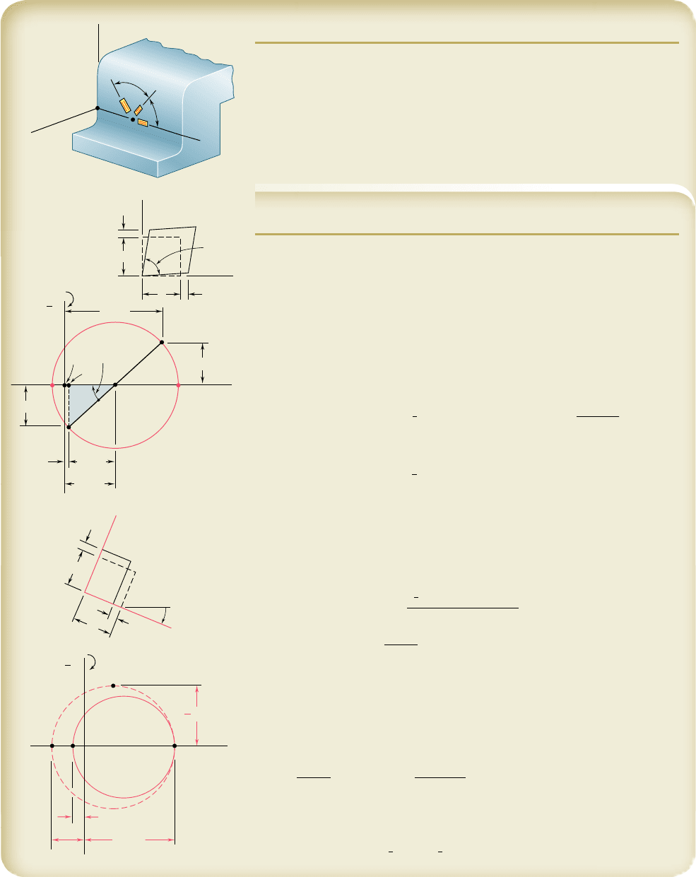
SAMPLE PROBLEM 7.7
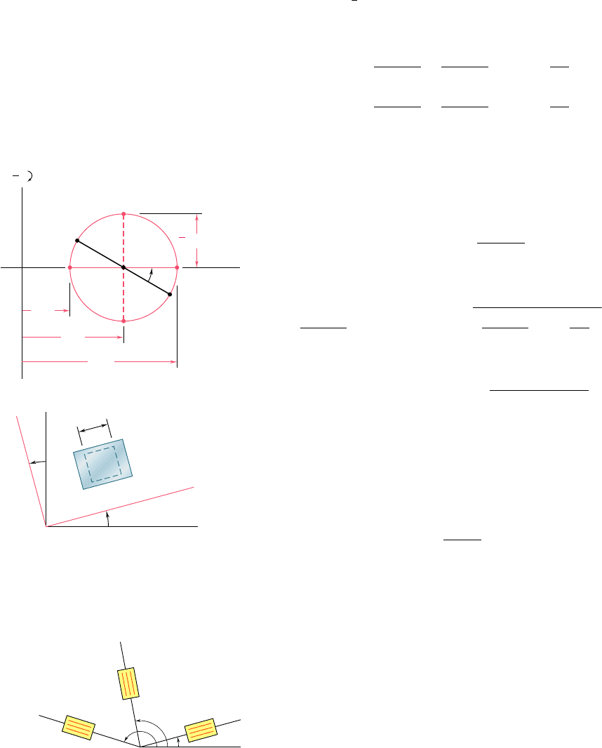
Using a 608 rosette, the following strains have been determined at point Q
on the surface of a steel machine base:
P
1
5
40
m P
2
5
980
m P
3
5
330
m
Using the coordinate axes shown, determine at point Q, (a) the strain com-
ponents P
x
, P
y
, and g
xy
, (b) the principal strains, (c) the maximum shearing
strain. (Use n 5 0.29.)
SOLUTION
a. Strain Components
e
x
,
e
y
, G
xy
. For the coordinate axes shown
u
1
5
0
u
2
5
60°
u
3
5
120°
Substituting these values into Eqs. (7.60), we have
P
1
5 P
x
1
1
2
1 P
y
1
0
2
1 g
xy
1
0
21
1
2
P
2
5 P
x
10.5002
2
1 P
y
10.8662
2
1 g
xy
10.866210.5002
P
3
5 P
x
120.5002
2
1 P
y
10.8662
2
1 g
xy
10.8662120.5002
Solving these equations for P
x
, P
y
, and g
xy
, we obtain
P
x
5
P
1
P
y
5
1
3
12P
2
1 2P
3
2 P
1
2
g
xy
5
P
2
2
P
3
0
.
866
Substituting the given values for P
1
, P
2
, and P
3
, we have
P
x
5
40
m P
y
5
1
3
32198021 2133022 404 P
y
51
860
m
◀
g
xy
5
1
980 2 330
2
y
0.866 g
xy
5 750 m
◀
These strains are indicated on the element shown.
b. Principal Strains. We note that the side of the element associated
with P
x
rotates counterclockwise; thus, we plot point X below the horizontal
axis, i.e., X(40, 2375). We then plot Y(860, 1375) and draw Mohr’s circle.
P
ave
5
1
2
1
860 m 1 40 m
2
5 450 m
R 5 2
1
375 m
2
2
1
1
410 m
2
2
5 556 m
tan 2u
p
5
375
m
410
m
2
u
p
5
42
.
4°i
u
p
5
21
.
2°i
Points A and B correspond to the principal strains. We have
P
a
5 P
ave
2 R 5 450
m
2 556
m
P
a
52
106
m
◀
P
b
5 P
ave
1 R 5 450
m
1 556
m
P
b
51
1006
m
◀
Since s
z
5 0 on the surface, we use Eq. (7.59) to find the principal strain P
c
:
P
c
52
n
1 2 n
1P
a
1 P
b
252
0
.
29
1 2 0
.
29
12106 m 1 1006 m2
P
c
52
368
m
◀
c. Maximum Shearing Strain. Plotting point C and drawing Mohr’s
circle through points B and C, we obtain point D9 and write
1
2
g
max
5
1
2
1
1006 m 1 368 m
2
g
max
5 13
7
4
m
◀
60
60
1
Q
O
x
z
y
2
3
y
x
xy
2
y
x
Y
O
F
A
X
R
B
C
1
375
410
450
40
1
860
90°
375
p
1
2
a
b
a
1
1
21.2
b
497
a
B
D'
AC
1006
368
1
2
1
2
max
bee80288_ch07_436-511.indd Page 497 10/30/10 3:33:42 PM user-f499bee80288_ch07_436-511.indd Page 497 10/30/10 3:33:42 PM user-f499/Users/user-f499/Desktop/Temp Work/Don't Delete Job/MHDQ251:Beer:201/ch07/Users/user-f499/Desktop/Temp Work/Don't Delete Job/MHDQ251:Beer:201/ch
Apago PDF Enhancer
PROBLEMS
498
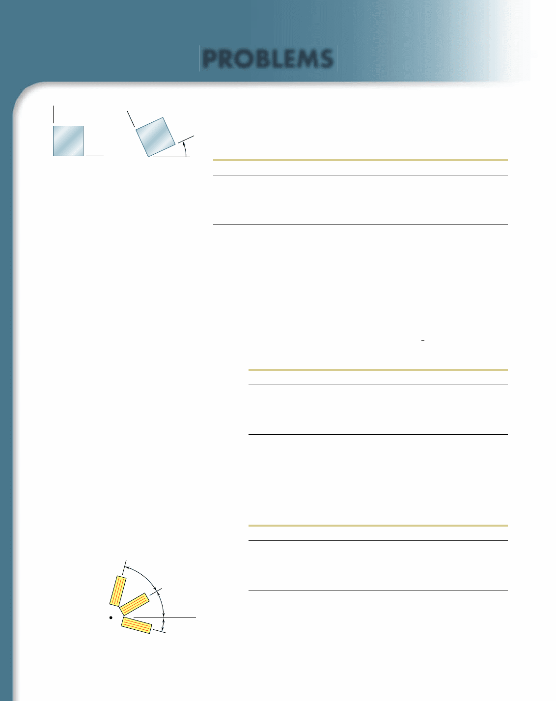
7.128 t hrou g h 7.131 For the given state of plane strain, use the
method of Sec. 7.10 to determine the state of plane strain associ-
ated with axes x9 and y9 rotated through the given angle u.
P
x
P
y
g
xy
u
7.128 and 7.132 2500m 1250m 0 158 l
7.129 and 7.133 1240m 1160m 1150m 608 i
7.130 and 7.134 2800m 1450m 1200m 258 i
7.131 and 7.135 0 1320m 2100m 308 l
7.132 through 7.135 For the given state of plane strain, use Mohr’s
circle to determine the state of plane strain associated with axes x9
and y9 rotated through the given angle u.
7.136 through 7.139 The following state of strain has been mea-
sured on the surface of a thin plate. Knowing that the surface of
the plate is unstressed, determine (a) the direction and magnitude
of the principal strains, (b) the maximum in-plane shearing strain,
(c) the maximum shearing strain. (Use
n 5
1
3
)
P
x
P
y
g
xy
7.136 2260m 260m 1480m
7.137 2600m 2400m 1350m
7.138 1160m 2480m 2600m
7.139 130m 1570m 1720m
7.14 0 t hrough 7.143 For the given state of plane strain, use Mohr’s
circle to determine(a) the orientation and magnitude of the prin-
cipal strains, (b) the maximum in-plane strain, (c) the maximum
shearing strain.
P
x
P
y
g
xy
7.140 160m 1240m 250m
7.141 1400m 1200m 1375m
7.142 1300m 160m 1100m
7.143 2180m 2260m 1315m
7.144 Determine the strain P
x
knowing that the following strains have
been determined by use of the rosette shown:
P
1
51
480m
P
2
52
120
m P
3
51
80
m
y
y'
x
'
x
Fig. P7.128 through P7.135
x
30
45
15
2
3
1
Fig. P7.144
bee80288_ch07_436-511.indd Page 498 10/30/10 3:33:54 PM user-f499bee80288_ch07_436-511.indd Page 498 10/30/10 3:33:54 PM user-f499/Users/user-f499/Desktop/Temp Work/Don't Delete Job/MHDQ251:Beer:201/ch07/Users/user-f499/Desktop/Temp Work/Don't Delete Job/MHDQ251:Beer:201/ch
Apago PDF Enhancer
499
Problems
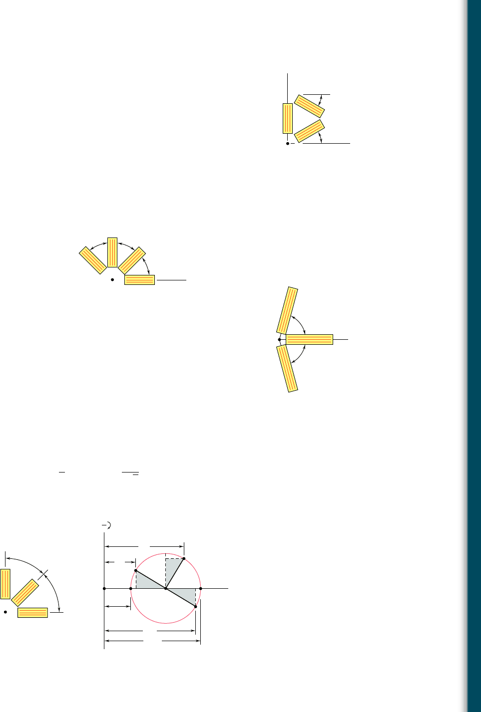
7.145 The strains determined by the use of the rosette shown during the
test of a machine element are
P
1
51
600
m P
2
514
5
0m P
3
52
75m
Determine (a) the in-plane principal strains, (b) the in-plane maxi-
mum shearing strain.
7.14 6 The rosette shown has been used to determine the following strains
at a point on the surface of a crane hook:
P
1
51420 3 10
2
6
in./in. P
2
5245 3 10
2
6
in./in.
P
4
51165 3 10
2
6
in./in.
(a) What should be the reading of gage 3? (b) Determine the
principal strains and the maximum in-plane shearing strain.
7.147 The strains determined by the use of the rosette attached as shown
during the test of a machine element are
P
1
5293.1 3 10
2
6
in./in. P
2
51385 3 10
2
6
in./in.
P
3
51210 3 10
2
6
in./in.
Determine (a) the orientation and magnitude of the principal
strains in the plane of the rosette, (b) the maximum in-plane shear-
ing strain.
7.148 Using a 458 rosette, the strains P
1,
P
2,
and P
3
have been determined
at a given point. Using Mohr’s circle, show that the principal strains
are:
P
max, min
5
1
2
1P
1
1 P
3
2 6
1
2
2
c1P
1
2 P
2
2
2
1 1P
2
2 P
3
2
2
d
1/2
(Hint: The shaded triangles are congruent.)
y
x
30
30
1
3
2
Fig. P7.145
x
45 45
45
2
3
4
1
Fig. P7.146
75
75
3
x
1
2
Fig. P7.147
O
A
C
B
min
1
3
2
max
2
45
45
2
3
1
Fig. P7.148
bee80288_ch07_436-511.indd Page 499 10/30/10 3:34:07 PM user-f499bee80288_ch07_436-511.indd Page 499 10/30/10 3:34:07 PM user-f499/Users/user-f499/Desktop/Temp Work/Don't Delete Job/MHDQ251:Beer:201/ch07/Users/user-f499/Desktop/Temp Work/Don't Delete Job/MHDQ251:Beer:201/ch
Apago PDF Enhancer
500
Transformations of Stress and Strain
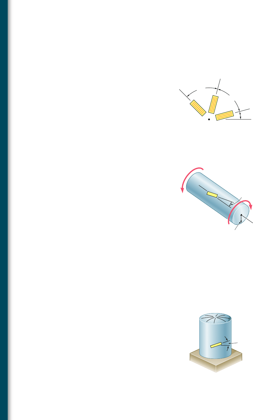
7.149 Show that the sum of the three strain measurements made with a 608
rosette is independent of the orientation of the rosette and equal to
P
1
1 P
2
1 P
3
5
3
P
avg
where P
avg
is the abscissa of the center of the corresponding Mohr’s
circle.
x
60⬚
60⬚
2
3
1
Fig. P7.149
2 in.
T
T'

Fig. P7.150
7.150 A single strain gage is cemented to a solid 4-in.-diameter steel shaft
at an angle b 5 258 with a line parallel to the axis of the shaft.
Knowing that G 5 11.5 3 10
6
psi, determine the torque T indi-
cated by a gage reading of 300 3 10
26
in./in.

Fig. P7.152
7.151 Solve Prob. 7.150, assuming that the gage forms an angle b 5 358
with a line parallel to the axis of the shaft.
7.152 A single strain gage forming an angle b 5 188 with a horizontal
plane is used to determine the gage pressure in the cylindrical steel
tank shown. The cylindrical wall of the tank is 6-mm thick, has a
600-mm inside diameter, and is made of a steel with E 5 200 GPa
and n 5 0.30. Determine the pressure in the tank indicated by a
strain gage reading of 280m.
7.153 Solve Prob. 7.152, assuming that the gage forms an angle b 5 358
with a horizontal plane.
bee80288_ch07_436-511.indd Page 500 11/19/10 2:58:08 PM user-f499bee80288_ch07_436-511.indd Page 500 11/19/10 2:58:08 PM user-f499 /Users/user-f499/Desktop/Temp Work/Don't Delete Job/MHDQ251:Beer:201/ch07/Users/user-f499/Desktop/Temp Work/Don't Delete Job/MHDQ251:Beer:201/ch07
Apago PDF Enhancer
501
Problems
7.154 The given state of plane stress is known to exist on the surface of a
machine component. Knowing that E 5 200 GPa and G 5 77.2 GPa,
determine the direction and magnitude of the three principal strains
(a) by determining the corresponding state of strain [use Eq. (2.43)
and Eq. (2.38)] and then using Mohr’s circle for strain, (b) by using
Mohr’s circle for stress to determine the principal planes and princi-
pal stresses and then determining the corresponding strains.
7.155 The following state of strain has been determined on the surface
of a cast-iron machine part:
P
x
52
7
20
m
P
y
52
400
m g
xy
51
660
m
Knowing that E 5 69 GPa and G 5 28 GPa, determine the prin-
cipal planes and principal stresses (a) by determining the corre-
sponding state of plane stress [use Eq. (2.36), Eq. (2.43), and the
first two equations of Prob. 2.72] and then using Mohr’s circle for
stress, (b) by using Mohr’s circle for strain to determine the orien-
tation and magnitude of the principal strains and then determine
the corresponding stresses.
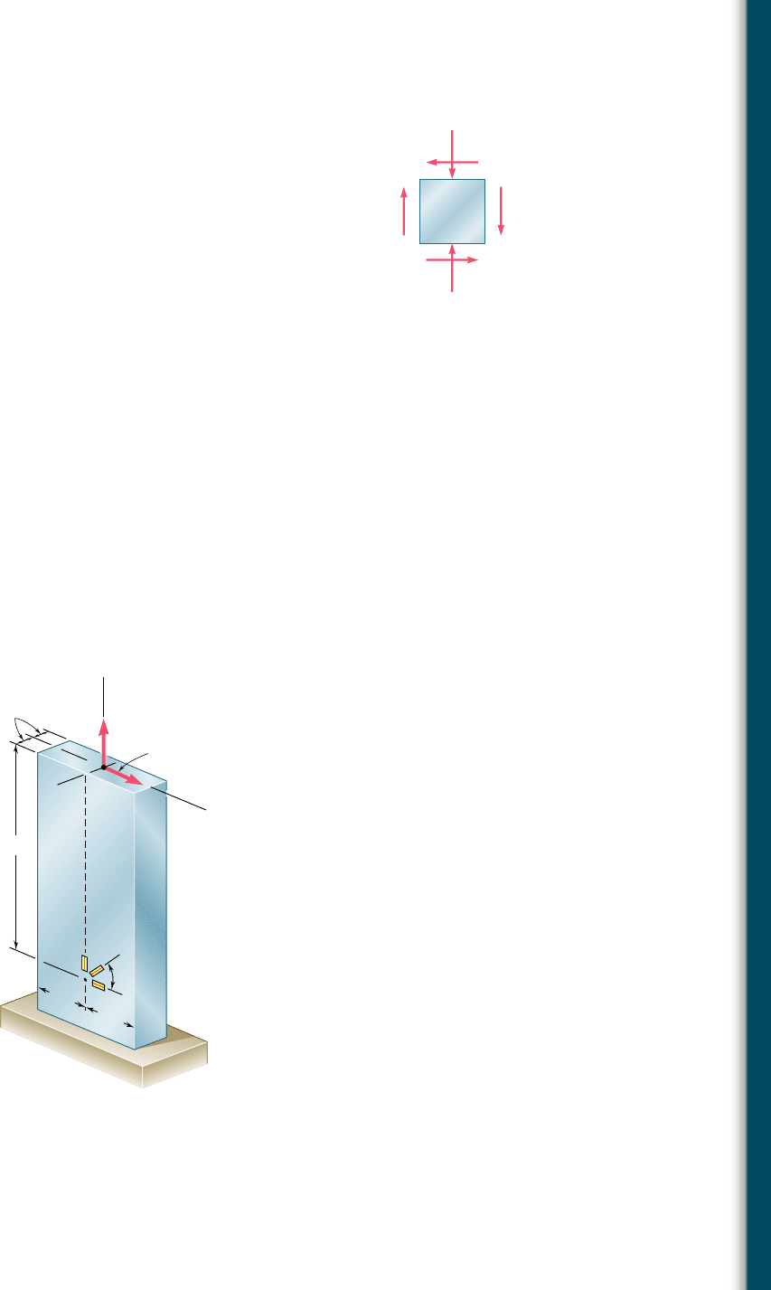
7.156 A centric axial force P and a horizontal force Q
x
are both applied
at point C of the rectangular bar shown. A 458 strain rosette on
the surface of the bar at point A indicates the following strains:
P
1
5260 3 10
2
6
in./in. P
2
51240 3 10
2
6
in./in.
P
3
51200 3 10
2
6
in./in.
Knowing that E 5 29 3 10
6
psi and n 5 0.30, determine the
magnitudes of P and Q
x
.
150 MPa
75 MP
a
Fig. P7.154
7.157 Solve Prob. 7.156, assuming that the rosette at point A indicates
the following strains:
P
1
5230 3 10
2
6
in./in. P
2
51250 3 10
2
6
in./in.
P
3
51100 3 10
2
6
in./in.
1 in.
y
C
A
P
Q
x
12 in.
3 in.
3 in.
3
2
45⬚
1
x
Fig. P7.156
bee80288_ch07_436-511.indd Page 501 11/29/10 6:44:40 PM user-f499bee80288_ch07_436-511.indd Page 501 11/29/10 6:44:40 PM user-f499 /Users/user-f499/Desktop/Temp Work/Don't Delete Job/MHDQ251:Beer:201/Users/user-f499/Desktop/Temp Work/Don't Delete Job/MHDQ251:Beer:201
Apago PDF Enhancer
502
REVIEW AND SUMMARY
xy
x'y'
y
y'
x
x'
Q
Q
z
xx
x
'
y
y'
z' z
y
(a)(b)
Fig. 7.77
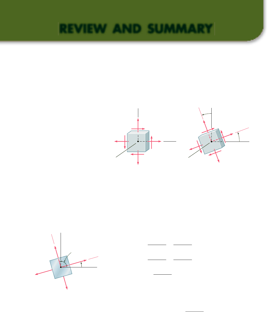
Considering first a state of plane stress at a given point Q [Sec. 7.2]
and denoting by s
x
, s
y
, and t
xy
the stress components associated
with the element shown in Fig. 7.77a, we derived the following for-
mulas defining the components s
x9
, s
y9
, and t
x9y9
associated with that
element after it had been rotated through an angle u about the z axis
(Fig. 7.77b):
s
x¿
5
s
x
1 s
y
2
1
s
x
2 s
y
2
cos 2u 1 t
xy
sin 2u
(7.5)
s
y¿
5
s
x
1 s
y
2
2
s
x
2 s
y
2
cos 2u 2 t
xy
sin 2u
(7.7)
t
x¿y¿
52
s
x
2
s
y
2
sin 2u 1 t
xy
cos 2u
(7.6)
In Sec. 7.3, we determined the values u
p
of the angle of rotation
which correspond to the maximum and minimum values of the nor-
mal stress at point Q. We wrote
tan 2u
p
5
2
t
xy
s
x
2 s
y
(7.12)
The two values obtained for u
p
are 908 apart (Fig. 7.78) and define
the principal planes of stress at point Q. The corresponding values
min
min
max
max
p
p
y
Q
x
y'
x
'
Fig. 7.78
Transformation of plane stress
The first part of this chapter was devoted to a study of the transfor-
mation of stress under a rotation of axes and to its application to the
solution of engineering problems, and the second part to a similar
study of the transformation of strain.
Principal planes. Principal stresses
bee80288_ch07_436-511.indd Page 502 10/30/10 3:34:31 PM user-f499bee80288_ch07_436-511.indd Page 502 10/30/10 3:34:31 PM user-f499/Users/user-f499/Desktop/Temp Work/Don't Delete Job/MHDQ251:Beer:201/ch07/Users/user-f499/Desktop/Temp Work/Don't Delete Job/MHDQ251:Beer:201/ch
Apago PDF Enhancer
503
of the normal stress are called the principal stresses at Q; we
obtained
s
max, min
5
s
x
1 s
y
2
6
B
a
s
x
2 s
y
2
b
2
1 t
2
x
y
(7.14)
We also noted that the corresponding value of the shearing stress is
zero. Next, we determined the values u
s
of the angle u for which the
largest value of the shearing stress occurs. We wrote
tan 2u
s
52
s
x
2
s
y
2t
x
y
(7.15)
The two values obtained for u
s
are 908 apart (Fig. 7.79). We also
noted that the planes of maximum shearing stress are at 458 to the
principal planes. The maximum value of the shearing stress for a
rotation in the plane of stress is
t
max
5
B
a
s
x
2 s
y
2
b
2
1 t
2
x
y
(7.16)
and the corresponding value of the normal stresses is
s¿ 5 s
ave
5
s
x
1 s
y
2
(7.17)
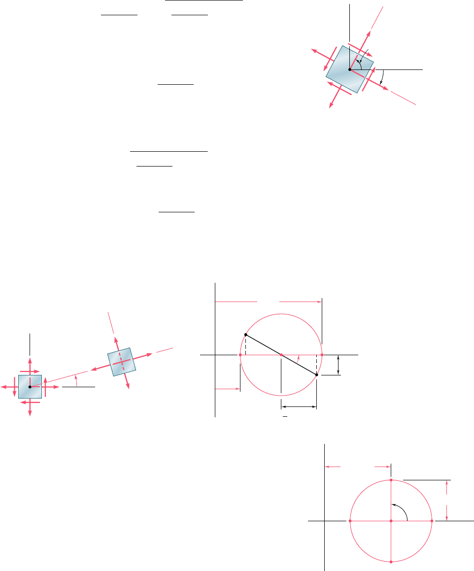
We saw in Sec. 7.4 that Mohr’s circle provides an alternative method,
based on simple geometric considerations, for the analysis of the
Review and Summary
max
max
s
s
y
Q
x
x'
y'
'
'
'
'
Fig. 7.79
Maximum in-plane shearing stress
Mohr’s circle for stress
transformation of plane stress. Given the state of stress shown in
black in Fig. 7.80a, we plot point X of coordinates s
x
, 2t
xy
and point
Y of coordinates s
y
, 1t
xy
(Fig. 7.80b). Drawing the circle of diame-
ter XY, we obtain Mohr’s circle. The abscissas of the points of inter-
section A and B of the circle with the horizontal axis represent the
principal stresses, and the angle of rotation bringing the diameter XY
into AB is twice the angle u
p
defining the principal planes in
Fig. 7.80a, with both angles having the same sense. We also noted
that diameter DE defines the maximum shearing stress and the
orientation of the corresponding plane (Fig. 7.81) [Example 7.02,
Sample Probs. 7.2 and 7.3].
max
min
x
y
(b)
O
BA
Y ,
C
⫺(
)
y
xy
⫹(
2
p
)
X ,
x
xy
xy
⫺(
)
1
2
p
y
max
max
min
min
x
xy
O
x
a
b
y
(a)
Fig. 7.80
ave
'
O BC A
D
E
max
90⬚
⫽
Fig. 7.81
bee80288_ch07_436-511.indd Page 503 11/17/10 11:16:26 PM user-f499bee80288_ch07_436-511.indd Page 503 11/17/10 11:16:26 PM user-f499 /Users/user-f499/Desktop/Temp Work/Don't Delete Job/MHDQ251:Beer:201/ch07/Users/user-f499/Desktop/Temp Work/Don't Delete Job/MHDQ251:Beer:201/ch07
Apago PDF Enhancer
504
Transformations of Stress and Strain
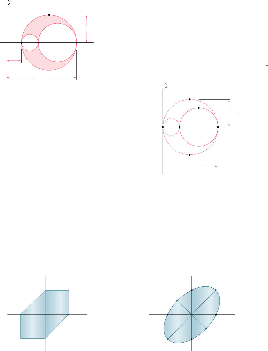
Considering a general state of stress characterized by six stress com-
ponents [Sec. 7.5], we showed that the normal stress on a plane of
arbitrary orientation can be expressed as a quadratic form of the direc-
tion cosines of the normal to that plane. This proves the existence of
three principal axes of stress and three principal stresses at any given
point. Rotating a small cubic element about each of the three principal
axes [Sec. 7.6], we drew the corresponding Mohr’s circles that yield
the values of s
max
, s
min
, and t
max
(Fig. 7.82). In the particular case of
plane stress, and if the x and y axes are selected in the plane of stress,
point C coincides with the origin O. If A and B are located on opposite
sides of O, the maximum shearing stress is equal to the maximum
“in-plane’’ shearing stress as determined in Secs. 7.3 or 7.4. If A and
B are located on the same side of O, this will not be the case. If s
a
.
s
b
. 0, for instance the maximum shearing stress is equal to
1
2
s
a
and
corresponds to a rotation out of the plane of stress (Fig. 7.83).
General state of stress
O
C
B
A
min
max
max
Fig. 7.82
Z O
B
A
0
min
max
max
D'
E'
D
1
2
a
a
Fig. 7.83
Yield criteria for ductile materials under plane stress were developed
in Sec. 7.7. To predict whether a structural or machine component will
fail at some critical point due to yield in the material, we first determine
the principal stresses s
a
and s
b
at that point for the given loading
condition. We then plot the point of coordinates s
a
and s
b
. If this point
falls within a certain area, the component is safe; if it falls outside, the
component will fail. The area used with the maximum-shearing-strength
criterion is shown in Fig. 7.84 and the area used with the maximum-
distortion-energy criterion in Fig. 7.85. We note that both areas depend
upon the value of the yield strength s
Y
of the material.
Yield criteria for ductile materials
Y
Y
a
Y
Y
b
O
Fig. 7.84
Y
Y
Y
a
Y
b
O
A
B
D
C
Fig. 7.85
bee80288_ch07_436-511.indd Page 504 10/30/10 3:34:48 PM user-f499bee80288_ch07_436-511.indd Page 504 10/30/10 3:34:48 PM user-f499/Users/user-f499/Desktop/Temp Work/Don't Delete Job/MHDQ251:Beer:201/ch07/Users/user-f499/Desktop/Temp Work/Don't Delete Job/MHDQ251:Beer:201/ch
Apago PDF Enhancer
505
Fracture criteria for brittle materials under plane stress were devel-
oped in Sec. 7.8 in a similar fashion. The most commonly used is
Mohr’s criterion, which utilizes the results of various types of test
available for a given material. The shaded area shown in Fig. 7.86 is
used when the ultimate strengths s
UT
and s
UC
have been deter-
mined, respectively, from a tension and a compression test. Again,
the principal stresses s
a
and s
b
are determined at a given point of
the structural or machine component being investigated. If the cor-
responding point falls within the shaded area, the component is safe;
if it falls outside, the component will rupture.
Review and Summary
Fracture criteria for brittle materials
Cylindrical pressure vessels
UT
UT
UC
UC
b
a
Fig. 7.86
z
1
1
2
2
y
x
t
r
Fig. 7.87
1
2
1
2
1
Fig. 7.88
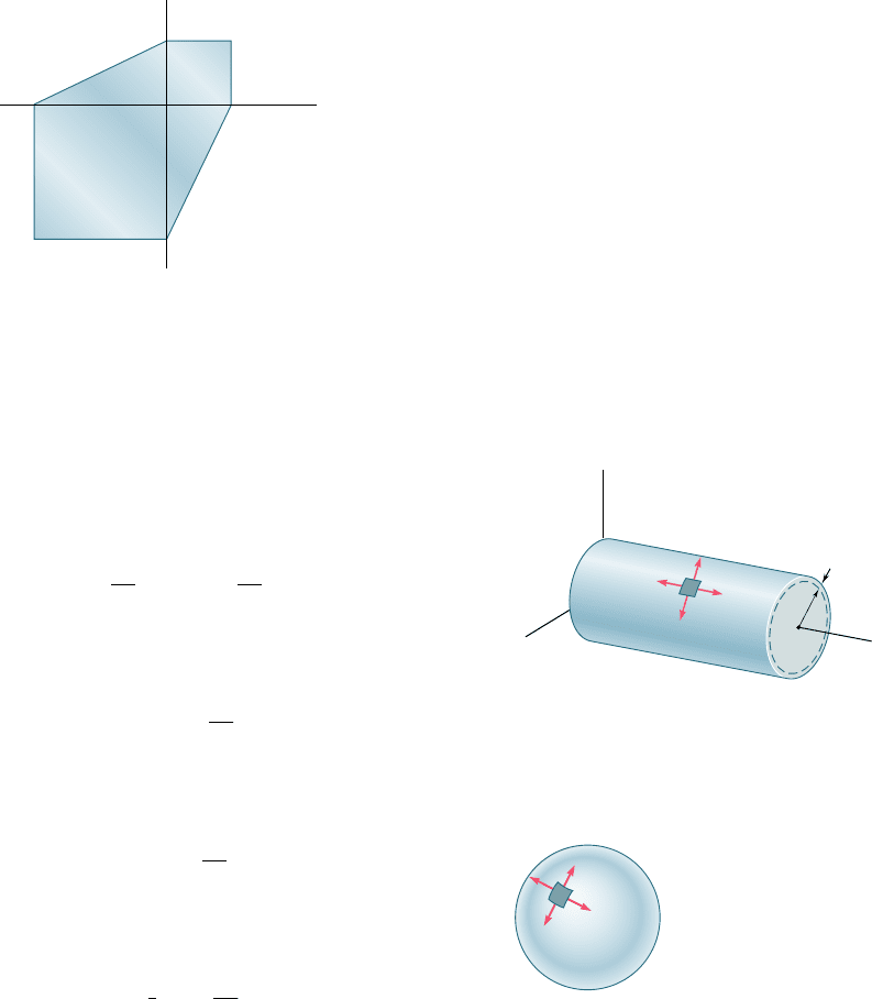
In Sec. 7.9, we discussed the stresses in thin-walled pressure vessels
and derived formulas relating the stresses in the walls of the vessels
and the gage pressure p in the fluid they contain. In the case of a
cylindrical vessel of inside radius r and thickness t (Fig. 7.87), we
obtained the following expressions for the hoop stress s
1
and the
longitudinal stress s
2
:
s
1
5
p
r
t
s
2
5
p
r
2
t
(7.30, 7.31)
We also found that the maximum shearing stress occurs out of the
plane of stress and is
t
max
5 s
2
5
p
r
2
t
(7.34)
In the case of a spherical vessel of inside radius r and thickness t
(Fig. 7.88), we found that the two principal stresses are equal:
s
1
5 s
2
5
p
r
2
t
(7.36)
Again, the maximum shearing stress occurs out of the plane of stress;
it is
t
max
5
1
2
s
1
5
p
r
4
t
(7.37)
Spherical pressure vessels
bee80288_ch07_436-511.indd Page 505 10/30/10 3:34:57 PM user-f499bee80288_ch07_436-511.indd Page 505 10/30/10 3:34:57 PM user-f499/Users/user-f499/Desktop/Temp Work/Don't Delete Job/MHDQ251:Beer:201/ch07/Users/user-f499/Desktop/Temp Work/Don't Delete Job/MHDQ251:Beer:201/ch
Apago PDF Enhancer
506
Transformations of Stress and Strain
s (1
s
min
)
s (1
max
)
C
O
max (in plane)
p
min
ave
max
2
1
X
2
p
p
A
b
a
B
Y
y
x
D
E
1
2
(a)
(b)
Fig. 7.89
The last part of the chapter was devoted to the transformation of
strain. In Secs. 7.10 and 7.11, we discussed the transformation of
plane strain and introduced Mohr’s circle for plane strain. The dis-
cussion was similar to the corresponding discussion of the transfor-
mation of stress, except that, where the shearing stress t was used,
we now used
1
2
g, that is, half the shearing strain. The formulas
obtained for the transformation of strain under a rotation of axes
through an angle u were
P
x¿
5
P
x
1 P
y
2
1
P
x
2 P
y
2
cos 2u 1
g
xy
2
sin 2u
(7.44)
P
y¿
5
P
x
1 P
y
2
2
P
x
2 P
y
2
cos 2u 2
g
xy
2
sin 2u
(7.45)
g
x¿
y
¿
52
1
P
x
2 P
y
2
sin 2u 1 g
x
y
cos 2u (7.49)
Using Mohr’s circle for strain (Fig. 7.89), we also obtained the fol-
lowing relations defining the angle of rotation u
p
corresponding to
the principal axes of strain and the values of the principal strains
P
max
and P
min
:
tan 2u
p
5
g
xy
P
x
2 P
y
(7.52)
P
max
5 P
ave
1 R and P
min
5 P
ave
2 R (7.51)
where
P
ave
5
P
x
1 P
y
2
and
R 5
B
a
P
x
2 P
y
2
b
2
1
a
g
xy
2
b
2
(7.50)
The maximum shearing strain for a rotation in the plane of strain
was found to be
g
max 1in
p
lane2
5 2R 5 21P
x
2 P
y
2
2
1 g
2
x
y
(7.53)
Section 7.12 was devoted to the three-dimensional analysis of
strain, with application to the determination of the maximum shear-
ing strain in the particular cases of plane strain and plane stress. In
the case of plane stress, we also found that the principal strain P
c
in
a direction perpendicular to the plane of stress could be expressed
as follows in terms of the “in-plane’’ principal strains P
a
and P
b
:
P
c
52
n
1 2 n
1P
a
1 P
b
2
(7.59)
Finally, we discussed in Sec. 7.13 the use of strain gages to measure
the normal strain on the surface of a structural element or machine
component. Considering a strain rosette consisting of three gages
aligned along lines forming respectively, angles u
1
, u
2
, and u
3
with
the x axis (Fig. 7.90), we wrote the following relations among the
measurements P
1
, P
2
, P
3
of the gages and the components P
x
, P
y
, g
xy
characterizing the state of strain at that point:
P
1
5 P
x
cos
2
u
1
1 P
y
sin
2
u
1
1 g
x
y
sin u
1
cos u
1
P
2
5 P
x
cos
2
u
2
1 P
y
sin
2
u
2
1 g
x
y
sin u
2
cos u
2
(7.60)
P
3
5 P
x
cos
2
u
3
1 P
y
sin
2
u
3
1 g
x
y
sin u
3
cos u
3
These equations can be solved for P
x
, P
y
, and g
xy
, once P
1
, P
2
,
and P
3
have been determined.
Transformation of plane strain
Mohr’s circle for strain
Strain gages. Strain rosette
L
1
L
2
L
3
O
x
2
1
3
2
3
1
Fig. 7.90
bee80288_ch07_436-511.indd Page 506 10/30/10 3:35:03 PM user-f499bee80288_ch07_436-511.indd Page 506 10/30/10 3:35:03 PM user-f499/Users/user-f499/Desktop/Temp Work/Don't Delete Job/MHDQ251:Beer:201/ch07/Users/user-f499/Desktop/Temp Work/Don't Delete Job/MHDQ251:Beer:201/ch
