Beer F.P., Johnston E.R., DeWolf J.T., Mazurek D.F. Mechanics of Materials
Подождите немного. Документ загружается.

Apago PDF Enhancer
517
each section, these ratios have been determined at 11 different
points, and the orientation of the principal axes has been indicated
at each point.†
It is clear that s
max
does not exceed s
m
in either of the two
sections considered in Fig. 8.8 and that, if it does exceed s
m
else-
where, it will be in sections close to the load P, where s
m
is small
compared to t
m
.‡ But, for sections close to the load P, Saint-Venant’s
principle does not apply, Eqs. (8.3) and (8.4) cease to be valid, except
in the very unlikely case of a load distributed parabolically over the
end section (cf. Sec. 6.5), and more advanced methods of analysis
taking into account the effect of stress concentrations should be
used. We thus conclude that, for beams of rectangular cross section,
and within the scope of the theory presented in this text, the maxi-
mum normal stress can be obtained from Eq. (8.1).
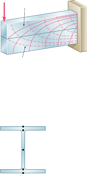
In Fig. 8.8 the directions of the principal axes were determined
at 11 points in each of the two sections considered. If this analysis
were extended to a larger number of sections and a larger number
of points in each section, it would be possible to draw two orthogonal
systems of curves on the side of the beam (Fig. 8.9). One system
would consist of curves tangent to the principal axes corresponding
to s
max
and the other of curves tangent to the principal axes corre-
sponding to s
min
. The curves obtained in this manner are known as
the stress trajectories. A trajectory of the first group (solid lines)
defines at each of its points the direction of the largest tensile stress,
while a trajectory of the second group (dashed lines) defines the
direction of the largest compressive stress.§
The conclusion we have reached for beams of rectangular cross
section, that the maximum normal stress in the beam can be obtained
from Eq. (8.1), remains valid for many beams of nonrectangular cross
section. However, when the width of the cross section varies in such
a way that large shearing stresses t
xy
will occur at points close to the
surface of the beam, where s
x
is also large, a value of the principal
stress s
max
larger than s
m
may result at such points. One should be
particularly aware of this possibility when selecting W-beams or
S-beams, and calculate the principal stress s
max
at the junctions b and
d of the web with the flanges of the beam (Fig. 8.10). This is done
by determining s
x
and t
xy
at that point from Eqs. (8.1) and (8.2),
respectively, and using either of the methods of analysis of Chap. 7
to obtain s
max
(see Sample Prob. 8.1). An alternative procedure, used
in design to select an acceptable section, consists of using for t
xy
the
maximum value of the shearing stress in the section, t
max
5 VyA
web
,
given by Eq. (6.11) of Sec. 6.4. This leads to a slightly larger, and thus
conservative, value of the principal stress s
max
at the junction of the
web with the flanges of the beam (see Sample Prob. 8.2).
8.2 Principal Stresses in a Beam
†See Prob. 8.C2, which refers to a program that can be written to obtain the results shown
in Fig. 8.8.
‡As will be verified in Prob. 8.C2, s
max
exceeds s
m
if x # 0.544c.
§A brittle material, such as concrete, will fail in tension along planes that are perpendicular
to the tensile-stress trajectories. Thus, to be effective, steel reinforcing bars should be
placed so that they intersect these planes. On the other hand, stiffeners attached to the
web of a plate girder will be effective in preventing buckling only if they intersect planes
perpendicular to the compressive-stress trajectories.
Tensile
Compressive
P
Fig. 8.9 Stress trajectories.
a
b
c
d
e
Fig. 8.10 Key stress
analysis locations
in I-shaped beams.
bee80288_ch08_512-547.indd Page 517 10/30/10 4:57:04 PM user-f499bee80288_ch08_512-547.indd Page 517 10/30/10 4:57:04 PM user-f499/Users/user-f499/Desktop/Temp Work/Don't Delete Job/MHDQ251:Beer:201/ch08/Users/user-f499/Desktop/Temp Work/Don't Delete Job/MHDQ251:Beer:201/ch
Apago PDF Enhancer
518
Principal Stresses under a Given Loading
*8.3 DESIGN OF TRANSMISSION SHAFTS
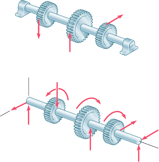
When we discussed the design of transmission shafts in Sec. 3.7, we
considered only the stresses due to the torques exerted on the shafts.
However, if the power is transferred to and from the shaft by means
of gears or sprocket wheels (Fig. 8.11a), the forces exerted on the
gear teeth or sprockets are equivalent to force-couple systems applied
at the centers of the corresponding cross sections (Fig. 8.11b). This
means that the shaft is subjected to a transverse loading, as well as
to a torsional loading.
The shearing stresses produced in the shaft by the transverse
loads are usually much smaller than those produced by the torques
and will be neglected in this analysis.† The normal stresses due to
the transverse loads, however, may be quite large and, as you will
see presently, their contribution to the maximum shearing stress t
max
should be taken into account.
†For an application where the shearing stresses produced by the transverse loads must be
considered, see Probs. 8.21 and 8.22.
C
A
B
P
1
P
2
P
3
C
(a)
C
A
y
A
z
P
2
P
3
T
3
T
2
T
1
P
1
C
(b)
y
z
B
z
B
y
x
Fig. 8.11 Loadings on gear-shaft systems.
bee80288_ch08_512-547.indd Page 518 10/30/10 4:57:09 PM user-f499bee80288_ch08_512-547.indd Page 518 10/30/10 4:57:09 PM user-f499/Users/user-f499/Desktop/Temp Work/Don't Delete Job/MHDQ251:Beer:201/ch08/Users/user-f499/Desktop/Temp Work/Don't Delete Job/MHDQ251:Beer:201/ch
Apago PDF Enhancer
519
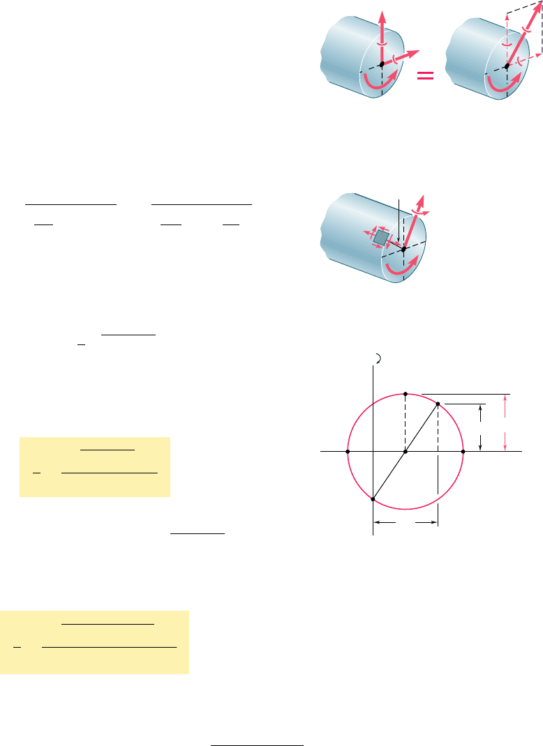
Consider the cross section of the shaft at some point C. We
represent the torque T and the bending couples M
y
and M
z
acting,
respectively, in a horizontal and a vertical plane by the couple vec-
tors shown (Fig. 8.12a). Since any diameter of the section is a prin-
cipal axis of inertia for the section, we can replace M
y
and M
z
by
their resultant M (Fig. 8.12b) in order to compute the normal
stresses s
x
exerted on the section. We thus find that s
x
is maximum
at the end of the diameter perpendicular to the vector representing
M (Fig. 8.13). Recalling that the values of the normal stresses at
that point are, respectively, s
m
5 McyI and zero, while the shearing
stress is t
m
5 TcyJ, we plot the corresponding points X and Y on a
Mohr-circle diagram (Fig. 8.14) and determine the value of the
maximum shearing stress:
t
max
5 R 5
B
a
s
m
2
b
2
1 1t
m
2
2
5
B
a
Mc
2I
b
2
1 a
Tc
J
b
2
Recalling that, for a circular or annular cross section, 2I 5 J, we
write
t
max
5
c
J
2M
2
1 T
2
(8.5)
It follows that the minimum allowable value of the ratio Jyc for
the cross section of the shaft is
J
c
5
A2M
2
1 T
2
B
max
t
a
ll
(8.6)
where the numerator in the right-hand member of the expression
obtained represents the maximum value of
2
M
2
1 T
2
in the shaft,
and t
all
the allowable shearing stress. Expressing the bending moment
M in terms of its components in the two coordinate planes, we can
also write
J
c
5
A2M
y
2
1 M
z
2
1 T
2
B
max
t
a
ll
(8.7)
Equations (8.6) and (8.7) can be used to design both solid and hollow
circular shafts and should be compared with Eq. (3.22) of Sec. 3.7,
which was obtained under the assumption of a torsional loading only.
The determination of the maximum value of 2M
y
2
1 M
z
2
1 T
2
will be facilitated if the bending-moment diagrams corresponding
to M
y
and M
z
are drawn, as well as a third diagram representing the
values of T along the shaft (see Sample Prob. 8.3).
8.3 Design of Transmission Shafts
C
M
z
M
y
C
M
(a)(b)
TT
Fig. 8.12 Resultant loading on the cross
section of a shaft.
m
m
m
M
T
Fig. 8.13 Maximum
stress element.
max
m
m
AC
X
Y
OB
D
Fig. 8.14 Mohr’s circle analysis.
bee80288_ch08_512-547.indd Page 519 11/18/10 7:43:05 PM user-f499bee80288_ch08_512-547.indd Page 519 11/18/10 7:43:05 PM user-f499 /Users/user-f499/Desktop/Temp Work/Don't Delete Job/MHDQ251:Beer:201/ch08/Users/user-f499/Desktop/Temp Work/Don't Delete Job/MHDQ251:Beer:201/ch08
Apago PDF Enhancer
520
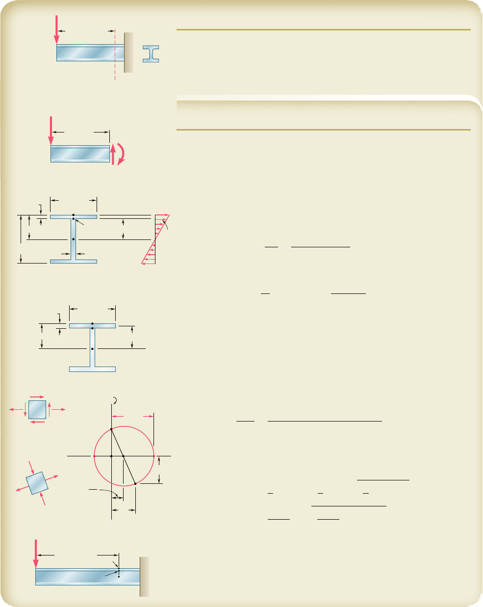
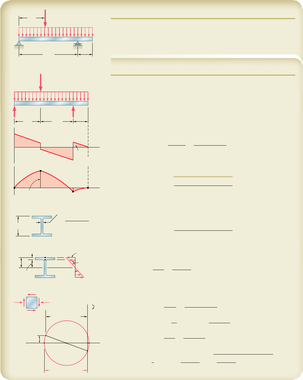
SAMPLE PROBLEM 8.1
A 160-kN force is applied as shown at the end of a W200 3 52 rolled-steel
beam. Neglecting the effect of fillets and of stress concentrations, determine
whether the normal stresses in the beam satisfy a design specification that
they be equal to or less than 150 MPa at section A-A9.
SOLUTION
Shear and Bending Moment. At section A-A9, we have
M
A
5
1
160 kN
21
0.375 m
2
5 60 kN ? m
V
A
5 160
k
N
Normal Stresses on Transverse Plane. Referring to the table of
Properties of Rolled-Steel Shapes in Appendix C, we obtain the data shown
and then determine the stresses s
a
and s
b
.
At point a:
s
a
5
M
A
S
5
60
k
N ? m
511 3 10
26
m
3
5 117.4 MPa
At point b:
s
b
5 s
a
y
b
c
5 1117.4 MPa2
90
.
4
mm
103 mm
5 103.0 MPa
We note that all normal stresses on the transverse plane are less than 150 MPa.
Shearing Stresses on Transverse Plane
At point a:
Q 5 0 t
a
5 0
At point b:
Q 5 1206 3 12.62196.725 251.0 3 10
3
mm
3
5 251.0 3 10
2
6
m
3
t
b
5
V
A
Q
It
5
1160 kN21251.0 3 10
2
6
m
3
2
1
52.9 3 10
26
m
4
21
0.00787 m
2
5 96.5 MPa
Principal Stress at Point b. The state of stress at point b consists of
the normal stress s
b
5 103.0 MPa and the shearing stress t
b
5 96.5 MPa.
We draw Mohr’s circle and find
s
max
5
1
2
s
b
1 R 5
1
2
s
b
1
B
a
1
2
s
b
b
2
1 t
b
2
5
103.0
2
1
B
a
103.0
2
b
2
1 196.52
2
s
m
a
x
5
160
.
9
MPa
The specification, s
max
# 150 MPa, is not satisfied
◀
Comment. For this beam and loading, the principal stress at point b
is 36% larger than the normal stress at point a. For L $ 881 mm, the maxi-
mum normal stress would occur at point a.
A
A'
160 kN
L 375 mm
V
A
M
A
0.375 m
160 kN
a
b
12.6 mm
206 mm
c 103 mm
206 mm
y
b
90.4 mm
7.87 mm
I 52.9 10
–6
m
4
S 511 10
–6
m
3
a
b
c
12.6 mm
206 mm
96.7 mm
103 mm
a
b
c
b
max
max
min
b
b
b
b
Y
X
A
OC
R
2
B
a
b
c
L 881 mm
W200 52
P
bee80288_ch08_512-547.indd Page 520 10/30/10 4:57:20 PM user-f499bee80288_ch08_512-547.indd Page 520 10/30/10 4:57:20 PM user-f499/Users/user-f499/Desktop/Temp Work/Don't Delete Job/MHDQ251:Beer:201/ch08/Users/user-f499/Desktop/Temp Work/Don't Delete Job/MHDQ251:Beer:201/ch
Apago PDF Enhancer
521
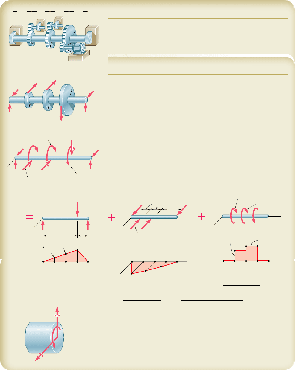
SAMPLE PROBLEM 8.2
The overhanging beam AB supports a uniformly distributed load of 3.2 kips/
ft and a concentrated load of 20 kips at C. Knowing that for the grade of
steel to be used s
all
5 24 ksi and t
all
5 14.5 ksi, select the wide-flange
shape that should be used.
SOLUTION
Reactions at A and D. We draw the free-body diagram of the beam.
From the equilibrium equations SM
D
5 0 and SM
A
5 0 we find the values
of R
A
and R
D
shown in the diagram.
Shear and Bending-Moment Diagrams. Using the methods of Secs.
5.2 and 5.3, we draw the diagrams and observe that
ƒ
M
ƒ
max
5 239.4 kip ? ft 5 2873 kip ? in.
ƒ
V
ƒ
max
5 43 kips
Section Modulus. For |M|
max
5 2873 kip ? in. and s
all
5 24 ksi, the
minimum acceptable section modulus of the rolled-steel shape is
S
min
5
ƒ M ƒ
max
s
a
ll
5
2873
k
ip ? in.
24 ksi
5 119.7 in
3
Selection of Wide-Flange Shape. From the table of Properties of
Rolled-Steel Shapes in Appendix C, we compile a list of the lightest shapes
of a given depth that have a section modulus larger than S
min
.
B
D
C
20 kips
3.2 kips/ft
9 ft
20 ft
5 ft
A
D
C
59 kips41 kips
41 kips
12.2 kips
16 kips
– 7.8 kips
239.4 kip · ft
– 43 kips
– 40 kip · ft
(– 279.4)
( 239.4)
(40)
9 ft 11 ft
5 ft
V
x
x
M
B
20 kips
3.2 kips/ft
A
t
w
0.400 in.
A
web
t
w
d 8.40 in
2
W21 62
S 127 in
3
d
21 in.
22.6 ksi
a
21.3 ksi
b
10.5 in.
9.88 in.
a
b
t
f
0.615 in.
A
C
O
B
Y
X
b
1.45 ksi
b
1.45 ksi
b
21.3 ksi
b
21.3 ksi
max
21.4 ksi
We now select the lightest shape available, namely W21 3 62
◀
Shearing Stress. Since we are designing the beam, we will conserva-
tively assume that the maximum shear is uniformly distributed over the web
area of a W21 3 62. We write
t
m
5
V
max
A
web
5
43
k
ips
8.40 in
2
5 5.12 ksi , 14.5 ksi
(OK)
Principal Stress at Point b. We check that the maximum principal
stress at point b in the critical section where M is maximum does not exceed
s
all
5 24 ksi. We write
s
a
5
M
max
S
5
2873
k
ip ? in.
12
7
in
3
5 22.6 ksi
s
b
5 s
a
y
b
c
5 122.6 ksi2
9
.
88
in.
10
.
50 in
.
5 21.3 ksi
Conservatively,
t
b
5
V
A
web
5
12.2
k
ips
8.40 in
2
5 1.45 ksi
We draw Mohr’s circle and find
s
max
5
1
2
s
b
1 R 5
21.3 ksi
2
1
B
a
21.3 ksi
2
b
2
1 11.45 ksi2
2
s
m
a
x
5 21.4
k
si # 24
k
si (OK)
◀
Shape S (in
3
)
W24 3 68 154
W21 3 62 127
W18 3 76 146
W16 3 77 134
W14 3 82 123
W12 3 96 131
bee80288_ch08_512-547.indd Page 521 11/17/10 11:55:04 PM user-f499bee80288_ch08_512-547.indd Page 521 11/17/10 11:55:04 PM user-f499 /Users/user-f499/Desktop/Temp Work/Don't Delete Job/MHDQ251:Beer:201/ch08/Users/user-f499/Desktop/Temp Work/Don't Delete Job/MHDQ251:Beer:201/ch08
Apago PDF Enhancer
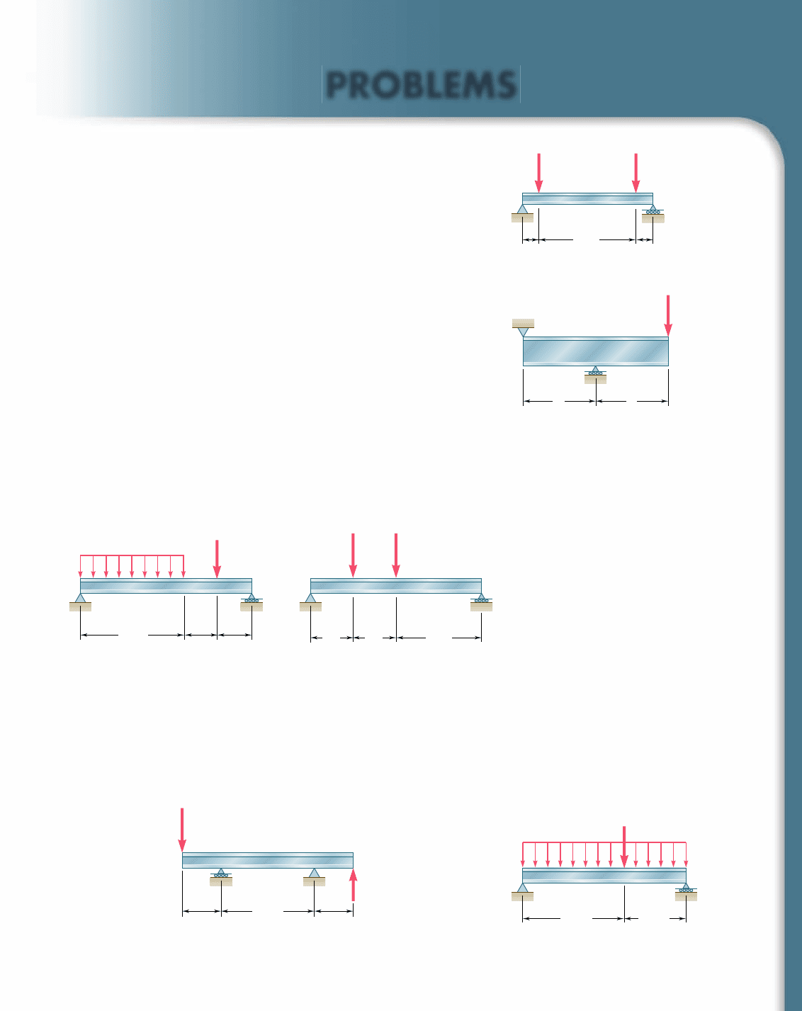
SAMPLE PROBLEM 8.3
The solid shaft AB rotates at 480 rpm and transmits 30 kW from the motor
M to machine tools connected to gears G and H; 20 kW is taken off at gear
G and 10 kW at gear H. Knowing that t
all
5 50 MPa, determine the smallest
permissible diameter for shaft AB.
SOLUTION
Torques Exerted on Gears. Observing that f 5 480 rpm 5 8 Hz, we
determine the torque exerted on gear E:
T
E
5
P
2p
f
5
30
k
W
2p18 Hz2
5 597 N ? m
The corresponding tangential force acting on the gear is
F
E
5
T
E
r
E
5
597 N ? m
0.16 m
5 3.73 kN
A similar analysis of gears C and D yields
T
C
5
20
k
W
2p
1
8 Hz
2
5 398 N ? mF
C
5 6.63 kN
T
D
5
10
k
W
2p
1
8 Hz
2
5 199 N ? mF
D
5 2.49 kN
We now replace the forces on the gears by equivalent force-couple systems.
Bending-Moment and Torque Diagrams
522
200
G
A
H
C
B
M
D
E
r
E
⫽ 160
r
C
⫽ 60
r
D
⫽ 80
200
Dimensions in mm
200 200
A
C
D
E
r
C
⫽ 0.060 m
r
E
⫽ 0.160 m
F
E
⫽ 3.73 kN
F
C
⫽ 6.63 kN
F
D
⫽ 2.49 kN
r
D
⫽ 0.080 m
B
A
C
D
E
y
T
D
⫽ 199 N · m
F
E
⫽ 3.73 kN
F
D
⫽ 2.49 kN
T
E
⫽ 597 N · m
F
C
⫽ 6.63 kN
T
C
⫽ 398 N · m
B
x
z
M
y
M
z
y
x
T
F
C
⫽ 6.63 kN
F
E
⫽ 3.73 kN
F
C
⫽ 6.63 kN
1244 N · m
1160 N · m
580 N · m
F
D
⫽ 2.49 kN T
E
⫽ 597 N · m
597 N · m
398 N · m
T
D
⫽ 199 N · m
T
C
⫽ 398 N · m
2.80 kN0.932 kN
0.6 m
373 N · m
560 N · m
186 N · m
0.2 m
A
E
y
B
x
z
M
z
ACDE B
6.22 kN
2.90 kN
0.2 m
0.4 m
A
A
y
BC
C
D
D
x
z
M
y
CD
E
B
A
A
y
T
B
B
C
C
D
D
E
E
x
z
Critical Transverse Section. By computing 2M
2
y
1 M
2
z
1 T
2
at all poten-
tially critical sections, we find that its maximum value occurs just to the right of D:
2M
2
y
1 M
2
z
1 T
2
max
5 2111602
2
1 13732
2
1 15972
2
5 1357 N ? m
Diameter of Shaft. For t
all
5 50 MPa, Eq. (7.32) yields
J
c
5
2M
2
y
1 M
2
z
1 T
2
ma
x
t
a
ll
5
1357 N ? m
50 MPa
5 27.14 3 10
26
m
3
For a solid circular shaft of radius c, we have
J
c
5
p
2
c
3
5 27.14 3 10
26
c 5 0.02585 m 5 25.85 mm
Di
a
m
ete
r 5 2
c
5 51
.
7 mm
◀
bee80288_ch08_512-547.indd Page 522 11/18/10 7:43:13 PM user-f499bee80288_ch08_512-547.indd Page 522 11/18/10 7:43:13 PM user-f499 /Users/user-f499/Desktop/Temp Work/Don't Delete Job/MHDQ251:Beer:201/ch08/Users/user-f499/Desktop/Temp Work/Don't Delete Job/MHDQ251:Beer:201/ch08
Apago PDF Enhancer
PROBLEMS
523
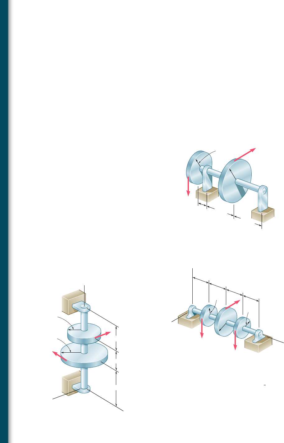
8.1 A W10 3 39 rolled-steel beam supports a load P as shown. Knowing
that P 5 45 kips, a 5 10 in., and s
all
5 18 ksi, determine (a) the
maximum value of the normal stress s
m
in the beam, (b) the maxi-
mum value of the principal stress s
max
at the junction of the flange
and web, (c) whether the specified shape is acceptable as far as these
two stresses are concerned.
8.2 Solve Prob. 8.1, assuming that P 5 22.5 kips and a 5 20 in.
8.3 An overhanging W920 3 449 rolled-steel beam supports a load
P as shown. Knowing that P 5 700 kN, a 5 2.5 m, and s
all
5
100 MPa, determine (a) the maximum value of the normal stress
s
m
in the beam, (b) the maximum value of the principal stress s
max
at the junction of the flange and web, (c) whether the specified
shape is acceptable as far as these two stresses are concerned.
8.4 Solve Prob. 8.3, assuming that P 5 850 kN and a 5 2.0 m.
8.5 and 8.6 (a) Knowing that s
all
5 24 ksi and t
all
5 14.5 ksi, select
the most economical wide-flange shape that should be used to
support the loading shown. (b) Determine the values to be expected
for s
m
, t
m
, and the principal stress s
max
at the junction of a flange
and the web of the selected beam.
8.7 and 8.8 (a) Knowing that s
all
5 160 MPa and t
all
5 100 MPa,
select the most economical metric wide-flange shape that should
be used to support the loading shown. (b) Determine the values
to be expected for s
m
, t
m
, and the principal stress s
max
at the junc-
tion of a flange and the web of the selected beam.
A
D
CB
aa
10 ft
PP
Fig. P8.1
P
B
C
A
aa
Fig. P8.3
D
B
C
12.5 kips
2 kips/ft
9 ft
3 ft 3 ft
A
Fig. P8.5
D
BC
6 ft 12 ft
A
6 ft
10 kips15 kips
Fig. P8.6
D
BC
A
1.5 m
3.6 m
1.5 m
275 kN
275 kN
Fig. P8.7
A
B
C
4.5 m 2.7 m
2.2 kN/m
40 kN
Fig. P8.8
bee80288_ch08_512-547.indd Page 523 10/30/10 4:58:08 PM user-f499bee80288_ch08_512-547.indd Page 523 10/30/10 4:58:08 PM user-f499/Users/user-f499/Desktop/Temp Work/Don't Delete Job/MHDQ251:Beer:201/ch08/Users/user-f499/Desktop/Temp Work/Don't Delete Job/MHDQ251:Beer:201/ch
Apago PDF Enhancer
524
Principal Stresses under a Given Loading
8.9 through 8.14 Each of the following problems refers to a
rolled-steel shape selected in a problem of Chap. 5 to support a
given loading at a minimal cost while satisfying the requirement
s
m
# s
all
. For the selected design, determine (a) the actual value
of s
m
in the beam, (b) the maximum value of the principal stress
s
max
at the junction of a flange and the web.
8.9 Loading of Prob. 5.73 and selected W530 3 66 shape.
8.10 Loading of Prob. 5.74 and selected W530 3 92 shape.
8.11 Loading of Prob. 5.77 and selected S15 3 42.9 shape.
8.12 Loading of Prob. 5.78 and selected S12 3 31.8 shape.
8.13 Loading of Prob. 5.75 and selected S460 3 81.4 shape.
8.14 Loading of Prob. 5.76 and selected S510 3 98.2 shape.
8.15 The vertical force P
1
and the horizontal force P
2
are applied as
shown to disks welded to the solid shaft AD. Knowing that the
diameter of the shaft is 1.75 in. and that t
all
5 8 ksi, determine
the largest permissible magnitude of the force P
2
.
8.16 The two 500-lb forces are vertical and the force P is parallel to the
z axis. Knowing that t
all
5 8 ksi, determine the smallest permissible
diameter of the solid shaft AE.
A
3 in.
10 in.
10 in.
8 in.
B
C
D
6 in.
P
1
P
2
Fig. P8.15
B
7 in.
7 in.
7 in.
7 in.
4 in.
4 in.
y
A
E
x
z
B
C
500 lb
P
6 in.
D
500 lb
Fig. P8.16
D
100 mm
60 mm
90 mm
4 kN
Q
B
C
A
y
z
x
80 mm
140 mm
Fig. P8.18
8.17 For the gear-and-shaft system and loading of Prob. 8.16, determine
the smallest permissible diameter of shaft AE, knowing that the shaft
is hollow and has an inner diameter that is
2
3
the outer diameter.
8.18 The 4-kN force is parallel to the x axis, and the force Q is parallel
to the z axis. The shaft AD is hollow. Knowing that the inner diam-
eter is half the outer diameter and that t
all
5 60 MPa, determine
the smallest permissible outer diameter of the shaft.
bee80288_ch08_512-547.indd Page 524 10/30/10 4:58:25 PM user-f499bee80288_ch08_512-547.indd Page 524 10/30/10 4:58:25 PM user-f499/Users/user-f499/Desktop/Temp Work/Don't Delete Job/MHDQ251:Beer:201/ch08/Users/user-f499/Desktop/Temp Work/Don't Delete Job/MHDQ251:Beer:201/ch
Apago PDF Enhancer
525
Problems
8.19 Neglecting the effect of fillets and of stress concentrations, deter-
mine the smallest permissible diameters of the solid rods BC and
CD. Use t
all
5 60 MPa.
8.20 Knowing that rods BC and CD are of diameter 24 mm and 36 mm,
respectively, determine the maximum shearing stress in each rod.
Neglect the effect of fillets and of stress concentrations.
8.21 It was stated in Sec. 8.3 that the shearing stresses produced in a
shaft by the transverse loads are usually much smaller than those
produced by the torques. In the preceding problems their effect
was ignored and it was assumed that the maximum shearing stress
in a given section occurred at point H (Fig. P8.21a) and was equal
to the expression obtained in Eq. (8.5), namely,
t
H
5
c
J
2M
2
1 T
2
Show that the maximum shearing stress at point K (Fig. P8.21b),
where the effect of the shear V is greatest, can be expressed as
t
K
5
c
J
B
1M cos b2
2
1 a
2
3
cV 1 Tb
2
where b is the angle between the vectors V and M. It is clear that
the effect of the shear V cannot be ignored when t
K
$ t
H
. (Hint:
Only the component of M along V contributes to the shearing
stress at K.)
8.22 Assuming that the magnitudes of the forces applied to disks A and
C of Prob. 8.15 are, respectively, P
1
5 1080 lb and P
2
5 810 lb,
and using the expressions given in Prob. 8.21, determine the values
of t
H
and t
K
in a section (a) just to the left of B, (b) just to the
left of C.
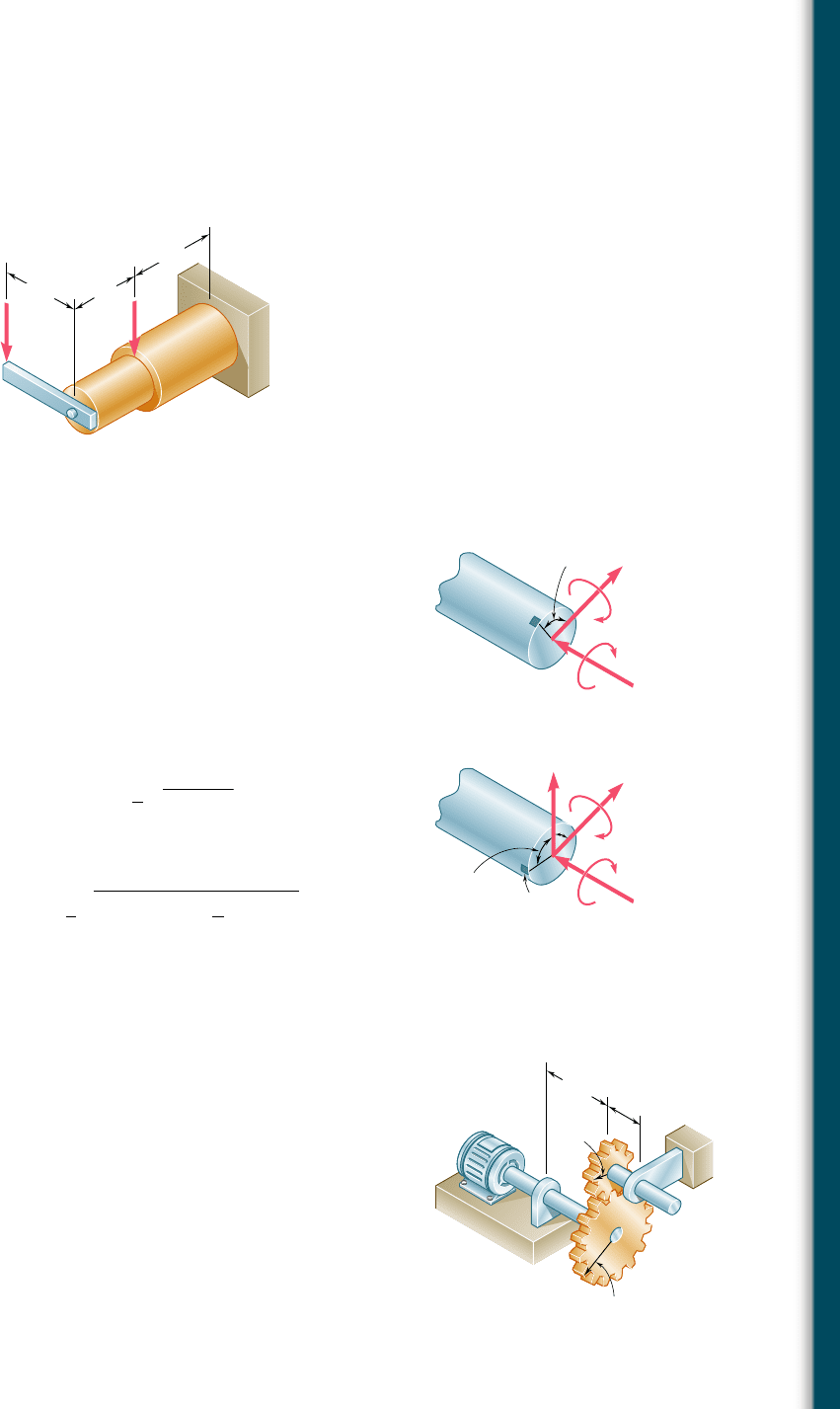
8.23 The solid shafts ABC and DEF and the gears shown are used to
transmit 20 hp from the motor M to a machine tool connected
to shaft DEF. Knowing that the motor rotates at 240 rpm and
that t
all
5 7.5 ksi, determine the smallest permissible diameter
of (a) shaft ABC, (b) shaft DEF.
8.24 Solve Prob. 8.23, assuming that the motor rotates at 360 rpm.
D
1250 N500 N
B
C
A
160 mm
200 mm
180 mm
Fig. P8.19 and P8.20
H
90
O
V
M
T
90
(a)
(b)
O
M
T
K
Fig. P8.21
M
A
B
3.5 in.
D
6 in.
8 in.
4 in.
E
F
C
Fig. P8.23
bee80288_ch08_512-547.indd Page 525 11/17/10 11:55:39 PM user-f499bee80288_ch08_512-547.indd Page 525 11/17/10 11:55:39 PM user-f499 /Users/user-f499/Desktop/Temp Work/Don't Delete Job/MHDQ251:Beer:201/ch08/Users/user-f499/Desktop/Temp Work/Don't Delete Job/MHDQ251:Beer:201/ch08
Apago PDF Enhancer
526
Principal Stresses under a Given Loading
8.25 The solid shaft AB rotates at 360 rpm and transmits 20 kW from
the motor M to machine tools connected to gears E and F. Knowing
that t
all
5 45 MPa and assuming that 10 kW is taken off at each
gear, determine the smallest permissible diameter of shaft AB.
M
120 mm
120 mm
0.2 m
0.2 m
0.2 m
A
C
F
E
B
D
Fig. P8.25
8.26 Solve Prob. 8.25, assuming that the entire 20 kW is taken off at
gear E.
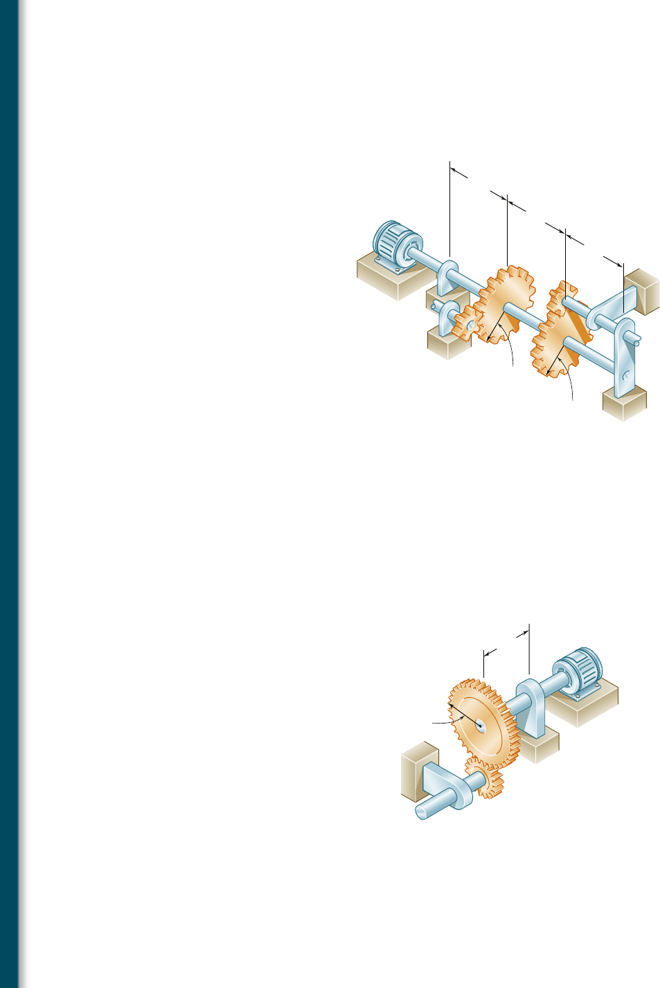
8.27 The solid shaft ABC and the gears shown are used to transmit
10 kW from the motor M to a machine tool connected to gear D.
Knowing that the motor rotates at 240 rpm and that t
all
5 60 MPa,
determine the smallest permissible diameter of shaft ABC.
90 mm
100 mm
M
C
B
D
E
C
A
Fig. P8.27
8.28 Assuming that shaft ABC of Prob. 8.27 is hollow and has an outer
diameter of 50 mm, determine the largest permissible inner diam-
eter of the shaft.
bee80288_ch08_512-547.indd Page 526 10/30/10 4:58:42 PM user-f499bee80288_ch08_512-547.indd Page 526 10/30/10 4:58:42 PM user-f499/Users/user-f499/Desktop/Temp Work/Don't Delete Job/MHDQ251:Beer:201/ch08/Users/user-f499/Desktop/Temp Work/Don't Delete Job/MHDQ251:Beer:201/ch
