Beer F.P., Johnston E.R., DeWolf J.T., Mazurek D.F. Mechanics of Materials
Подождите немного. Документ загружается.

Apago PDF Enhancer
547
Computer Problems
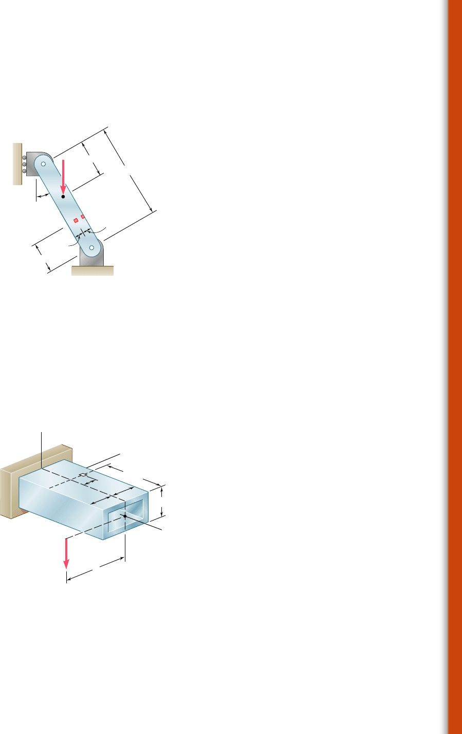
8.C6 Member AB has a rectangular cross section of 10 3 24 mm. For
the loading shown, write a computer program that can be used to determine
the normal and shearing stresses at points H and K for values of d from 0 to
120 mm, using 15-mm increments. Use this program to solve Prob. 8.35.
*8.C7 The structural tube shown has a uniform wall thickness of 0.3 in.
A 9-kip force is applied at a bar (not shown) that is welded to the end of
the tube. Write a computer program that can be used to determine, for any
given value of c, the principal stresses, principal planes, and maximum
shearing stress at point H for values of d from 23 in. to 3 in., using one-
inch increments. Use this program to solve Prob. 8.62a.
30
120 mm
K
H
d
B
A
12 mm
12 mm
40 mm
9 kN
Fig. P8.C6
H
x
z
c
y
d
3 in.
3 in.
9 kips
4 in.
10 in.
Fig. P8.C7
bee80288_ch08_512-547.indd Page 547 10/30/10 5:02:45 PM user-f499bee80288_ch08_512-547.indd Page 547 10/30/10 5:02:45 PM user-f499/Users/user-f499/Desktop/Temp Work/Don't Delete Job/MHDQ251:Beer:201/ch08/Users/user-f499/Desktop/Temp Work/Don't Delete Job/MHDQ251:Beer:201/ch

Apago PDF Enhancer
The photo shows a multiple-girder
bridge during construction. The design
of the steel girders is based on both
strength considerations and deflection
evaluations.
548
bee80288_ch09_548-629.indd Page 548 10/30/10 11:14:28 PM user-f499bee80288_ch09_548-629.indd Page 548 10/30/10 11:14:28 PM user-f499 /Users/user-f499/Desktop/Temp Work/Don't Delete Job/MHDQ251:Beer:201/ch09/Users/user-f499/Desktop/Temp Work/Don't Delete Job/MHDQ251:Beer:201/ch09

Apago PDF Enhancer
549
Deflection of Beams
9
CHAPTER
bee80288_ch09_548-629.indd Page 549 10/30/10 11:16:42 PM user-f499bee80288_ch09_548-629.indd Page 549 10/30/10 11:16:42 PM user-f499 /Users/user-f499/Desktop/Temp Work/Don't Delete Job/MHDQ251:Beer:201/ch09/Users/user-f499/Desktop/Temp Work/Don't Delete Job/MHDQ251:Beer:201/ch09
Apago PDF Enhancer
550
Chapter 9 Deflection of Beams
9.1 Introduction
9.2 Deformation of a Beam under
Transverse Loading
9.3 Equation of the Elastic Curve
*9.4 Direct Determination of the
Elastic Curve from the Load
Distribution
9.5 Statically Indeterminate Beams
*9.6 Using Singularity Functions to
Determine the Slope and
Deflection of a Beam
9.7 Method of Superposition
9.8 Application of Superposition to
Statically Indeterminate Beams
*9.9 Moment-Area Theorems
*9.10 Application to Cantilever Beams
and Beams with Symmetric
Loadings
*9.11 Bending-Moment Diagrams by
Parts
*9.12
Application of Moment-Area
Theorems to Beams with
Unsymmetric Loadings
*9.13 Maximum Deflection
*9.14 Use of Moment-Area Theorems
with Statically Indeterminate
Beams
9.1 INTRODUCTION
In the preceding chapter we learned to design beams for strength.
In this chapter we will be concerned with another aspect in the
design of beams, namely, the determination of the deflection. Of
particular interest is the determination of the maximum deflection of
a beam under a given loading, since the design specifications of a
beam will generally include a maximum allowable value for its deflec-
tion. Also of interest is that a knowledge of the deflections is required
to analyze indeterminate beams. These are beams in which the num-
ber of reactions at the supports exceeds the number of equilibrium
equations available to determine these unknowns.
We saw in Sec. 4.4 that a prismatic beam subjected to pure
bending is bent into an arc of circle and that, within the elastic range,
the curvature of the neutral surface can be expressed as
1
r
5
M
EI
(4.21)
where M is the bending moment, E the modulus of elasticity, and I
the moment of inertia of the cross section about its neutral axis.
When a beam is subjected to a transverse loading, Eq. (4.21)
remains valid for any given transverse section, provided that Saint-
Venant’s principle applies. However, both the bending moment and
the curvature of the neutral surface will vary from section to section.
Denoting by x the distance of the section from the left end of the
beam, we write
1
r
5
M1x
2
EI
(9.1)
The knowledge of the curvature at various points of the beam will
enable us to draw some general conclusions regarding the deforma-
tion of the beam under loading (Sec. 9.2).
To determine the slope and deflection of the beam at any given
point, we first derive the following second-order linear differential
equation, which governs the elastic curve characterizing the shape of
the deformed beam (Sec. 9.3):
d
2
y
d
x
2
5
M1x
2
EI
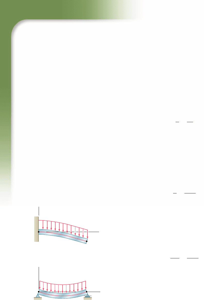
If the bending moment can be represented for all values of x
by a single function M(x), as in the case of the beams and loadings
shown in Fig. 9.1, the slope u 5 dyydx and the deflection y at any
point of the beam may be obtained through two successive integra-
tions. The two constants of integration introduced in the process
will be determined from the boundary conditions indicated in the
figure.
However, if different analytical functions are required to
represent the bending moment in various portions of the beam,
different differential equations will also be required, leading to
B
B
x
A
A
y
y
(a) Cantilever beam
(b) Simply supported beam
[ y
A
0 ] [ y
B
0 ]
x
[ y
A
0]
[
A
0]
Fig. 9.1 Situations where bending
moment can be given by a single
function M(x).
bee80288_ch09_548-629.indd Page 550 10/30/10 11:16:52 PM user-f499bee80288_ch09_548-629.indd Page 550 10/30/10 11:16:52 PM user-f499 /Users/user-f499/Desktop/Temp Work/Don't Delete Job/MHDQ251:Beer:201/ch09/Users/user-f499/Desktop/Temp Work/Don't Delete Job/MHDQ251:Beer:201/ch09
Apago PDF Enhancer
551
9.1 Introduction
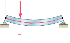
different functions defining the elastic curve in the various por-
tions of the beam. In the case of the beam and loading of Fig. 9.2,
for example, two differential equations are required, one for the
portion of beam AD and the other for the portion DB. The first
equation yields the functions u
1
and y
1
, and the second the func-
tions u
2
and y
2
. Altogether, four constants of integration must be
determined; two will be obtained by writing that the deflection is
zero at A and B, and the other two by expressing that the portions
of beam AD and DB have the same slope and the same deflection
at D.
You will observe in Sec. 9.4 that in the case of a beam support-
ing a distributed load w(x), the elastic curve can be obtained directly
from w(x) through four successive integrations. The constants intro-
duced in this process will be determined from the boundary values
of V, M, u, and y.
In Sec. 9.5, we will discuss statically indeterminate beams
where the reactions at the supports involve four or more unknowns.
The three equilibrium equations must be supplemented with equa-
tions obtained from the boundary conditions imposed by the
supports.
The method described earlier for the determination of the
elastic curve when several functions are required to represent the
bending moment M can be quite laborious, since it requires match-
ing slopes and deflections at every transition point. You will see in
Sec. 9.6 that the use of singularity functions (previously discussed in
Sec. 5.5) considerably simplifies the determination of u and y at any
point of the beam.
The next part of the chapter (Secs. 9.7 and 9.8) is devoted to
the method of superposition, which consists of determining sepa-
rately, and then adding, the slope and deflection caused by the vari-
ous loads applied to a beam. This procedure can be facilitated by
the use of the table in Appendix D, which gives the slopes and
deflections of beams for various loadings and types of support.
In Sec. 9.9, certain geometric properties of the elastic curve
will be used to determine the deflection and slope of a beam at a
given point. Instead of expressing the bending moment as a function
M(x) and integrating this function analytically, the diagram represent-
ing the variation of MyEI over the length of the beam will be drawn
and two moment-area theorems will be derived. The first moment-
area theorem will enable us to calculate the angle between the tan-
gents to the beam at two points; the second moment-area theorem
will be used to calculate the vertical distance from a point on the
beam to a tangent at a second point.
The moment-area theorems will be used in Sec. 9.10 to deter-
mine the slope and deflection at selected points of cantilever beams
and beams with symmetric loadings. In Sec. 9.11 you will find that
in many cases the areas and moments of areas defined by the MyEI
diagram may be more easily determined if you draw the bending-
moment diagram by parts. As you study the moment-area method,
you will observe that this method is particularly effective in the case
of beams of variable cross section.
B
A
D
y
[
x 0, y
1
0]
x
x
L,
1
2
1
4
[
[
x L, y
1
y
2
1
4
[
[
x L, y
2
0
[
[
P
Fig. 9.2 Situation where two sets of
equations are required.
bee80288_ch09_548-629.indd Page 551 10/30/10 11:16:57 PM user-f499bee80288_ch09_548-629.indd Page 551 10/30/10 11:16:57 PM user-f499 /Users/user-f499/Desktop/Temp Work/Don't Delete Job/MHDQ251:Beer:201/ch09/Users/user-f499/Desktop/Temp Work/Don't Delete Job/MHDQ251:Beer:201/ch09
Apago PDF Enhancer
552
Defl ection of Beams
Beams with unsymmetric loadings and overhanging beams will
be considered in Sec. 9.12. Since for an unsymmetric loading the
maximum deflection does not occur at the center of a beam, you will
learn in Sec. 9.13 how to locate the point where the tangent is hori-
zontal in order to determine the maximum deflection. Section 9.14
will be devoted to the solution of problems involving statically inde-
terminate beams.
9.2 DEFORMATION OF A BEAM UNDER
TRANSVERSE LOADING
At the beginning of this chapter, we recalled Eq. (4.21) of Sec. 4.4,
which relates the curvature of the neutral surface and the bending
moment in a beam in pure bending. We pointed out that this equa-
tion remains valid for any given transverse section of a beam sub-
jected to a transverse loading, provided that Saint-Venant’s principle
applies. However, both the bending moment and the curvature of
the neutral surface will vary from section to section. Denoting by x
the distance of the section from the left end of the beam, we write
1
r
5
M1x
2
EI
(9.1)
Consider, for example, a cantilever beam AB of length L sub-
jected to a concentrated load P at its free end A (Fig. 9.3a). We have
M(x) 5 2Px and, substituting into (9.1),
1
r
52
Px
EI
which shows that the curvature of the neutral surface varies linearly
with x, from zero at A, where r
A
itself is infinite, to 2PLyEI at B,
where |r
B
| 5 EIyPL (Fig. 9.3b).
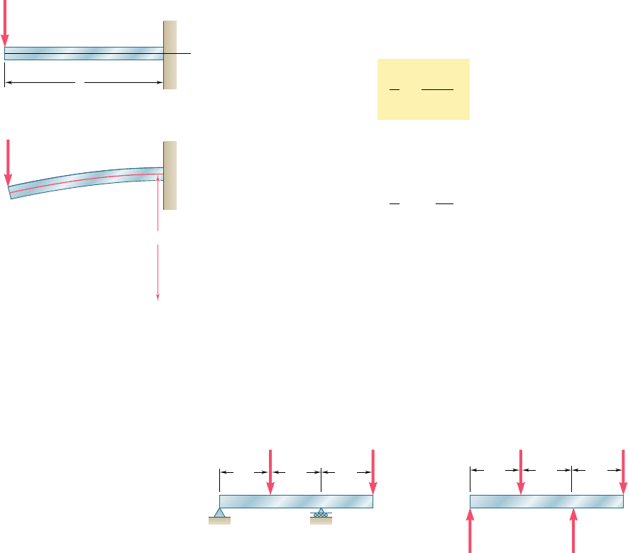
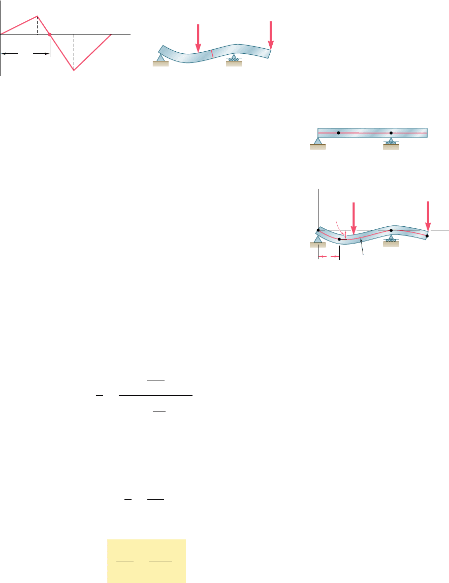
Consider now the overhanging beam AD of Fig. 9.4a that sup-
ports two concentrated loads as shown. From the free-body diagram
of the beam (Fig. 9.4b), we find that the reactions at the supports are
R
A
5 1 kN and R
C
5 5 kN, respectively, and draw the corresponding
bending-moment diagram (Fig. 9.5a). We note from the diagram that
M, and thus the curvature of the beam, are both zero at each end of
the beam, and also at a point E located at x 5 4 m. Between A and
E the bending moment is positive and the beam is concave upward;
B
A
x
A
(a)
P
L
A
(b)
P
B
B
Fig. 9.3 Cantilever beam with
concentrated load.
(a)
Fig. 9.4 Overhanging beam with two concentrated loads.
(b)
DA
B C
4 kN
2 kN
R
C
5 kNR
A
1 kN
3 m 3 m 3 m
D
B
C
A
4 kN
2 kN
3 m 3 m 3 m
bee80288_ch09_548-629.indd Page 552 10/30/10 11:17:00 PM user-f499bee80288_ch09_548-629.indd Page 552 10/30/10 11:17:00 PM user-f499 /Users/user-f499/Desktop/Temp Work/Don't Delete Job/MHDQ251:Beer:201/ch09/Users/user-f499/Desktop/Temp Work/Don't Delete Job/MHDQ251:Beer:201/ch09
Apago PDF Enhancer
553
between E and D the bending moment is negative and the beam is
concave downward (Fig. 9.5b). We also note that the largest value of
the curvature (i.e., the smallest value of the radius of curvature)
occurs at the support C, where |M| is maximum.
From the information obtained on its curvature, we get a fairly
good idea of the shape of the deformed beam. However, the analysis
and design of a beam usually require more precise information on
the deflection and the slope of the beam at various points. Of par-
ticular importance is the knowledge of the maximum deflection of
the beam. In the next section Eq. (9.1) will be used to obtain a
relation between the deflection y measured at a given point Q on
the axis of the beam and the distance x of that point from some fixed
origin (Fig. 9.6). The relation obtained is the equation of the elastic
curve, i.e., the equation of the curve into which the axis of the beam
is transformed under the given loading (Fig. 9.6b).†
9.3 EQUATION OF THE ELASTIC CURVE
We first recall from elementary calculus that the curvature of a plane
curve at a point Q(x,y) of the curve can be expressed as
1
r
5
d
2
y
dx
2
c1 1 a
d
y
dx
b
2
d
3
y
2
(9.2)
where dyydx and d
2
yydx
2
are the first and second derivatives of the
function y(x) represented by that curve. But, in the case of the elastic
curve of a beam, the slope dyydx is very small, and its square is
negligible compared to unity. We write, therefore,
1
r
5
d
2
y
dx
2
(9.3)
Substituting for 1yr from (9.3) into (9.1), we have
d
2
y
d
x
2
5
M1x
2
EI
(9.4)
9.3 Equation of the Elastic Curve
†It should be noted that, in this chapter, y represents a vertical displacement, while it was
used in previous chapters to represent the distance of a given point in a transverse section
from the neutral axis of that section.
M
A
B
EC D
4 m
3 kN · m
⫺6 kN · m
x
(a)
C
D
4 kN
2 kN
B
E
A
(b)
Fig. 9.5 Moment-curvature relationship for beam of Fig. 9.4.
D
C
Q
A
(a)
(b)
C
y
x
y
A
D
Q
x
Elastic
curve
P
2
P
1
Fig. 9.6 Elastic curve for beam of
Fig. 9.4.
bee80288_ch09_548-629.indd Page 553 11/19/10 3:17:02 PM user-f499bee80288_ch09_548-629.indd Page 553 11/19/10 3:17:02 PM user-f499 /Users/user-f499/Desktop/Temp Work/Don't Delete Job/MHDQ251:Beer:201/ch09/Users/user-f499/Desktop/Temp Work/Don't Delete Job/MHDQ251:Beer:201/ch09
Apago PDF Enhancer
554
Defl ection of Beams
The equation obtained is a second-order linear differential equation;
it is the governing differential equation for the elastic curve.
The product EI is known as the flexural rigidity and, if it varies
along the beam, as in the case of a beam of varying depth, we must
express it as a function of x before proceeding to integrate Eq. (9.4).
However, in the case of a prismatic beam, which is the case consid-
ered here, the flexural rigidity is constant. We may thus multiply both
members of Eq. (8.4) by EI and integrate in x. We write
EI
dy
dx
5
#
x
0
M1x2 dx 1 C
1
(9.5)
where C
1
is a constant of integration. Denoting by u(x) the angle,
measured in radians, that the tangent to the elastic curve at Q forms
with the horizontal (Fig. 9.7), and recalling that this angle is very
small, we have
d
y
d
x
5 tan u . u1x2
Thus, we write Eq. (9.5) in the alternative form
EI u1x25
#
x
0
M1x2 dx 1 C
1
(9.59)
Integrating both members of Eq. (9.5) in x, we have
EI y 5
#
x
0
c
#
x
0
M1x2 dx 1 C
1
d
dx 1 C
2
EI y 5
#
x
0
dx
#
x
0
M1x2 dx 1 C
1
x 1 C
2
(9.6)
where C
2
is a second constant, and where the first term in the right-
hand member represents the function of x obtained by integrating
twice in x the bending moment M(x). If it were not for the fact that
the constants C
1
and C
2
are as yet undetermined, Eq. (9.6) would
define the deflection of the beam at any given point Q, and Eq. (9.5)
or (9.59) would similarly define the slope of the beam at Q.
The constants C
1
and C
2
are determined from the boundary
conditions or, more precisely, from the conditions imposed on the
beam by its supports. Limiting our analysis in this section to statically
determinate beams, i.e., to beams supported in such a way that the
reactions at the supports can be obtained by the methods of statics,
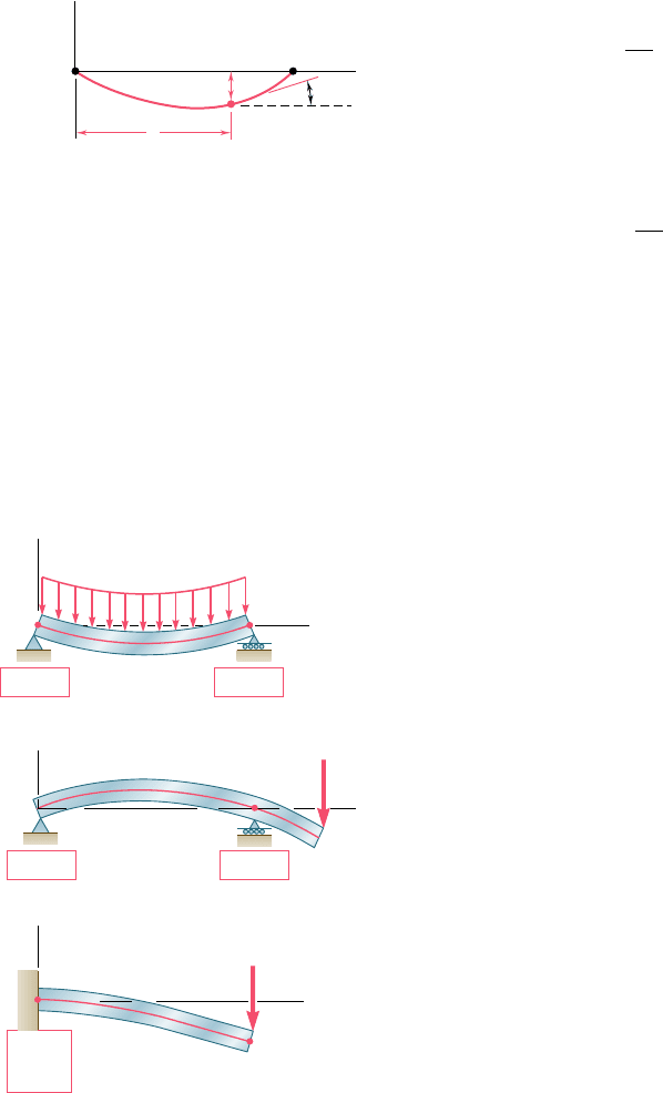
we note that only three types of beams need to be considered here
(Fig. 9.8): (a) the simply supported beam, (b) the overhanging beam,
and (c) the cantilever beam.
In the first two cases, the supports consist of a pin and bracket
at A and of a roller at B, and require that the deflection be zero at
each of these points. Letting first x 5 x
A
, y 5 y
A
5 0 in Eq. (9.6),
and then x 5 x
B
, y 5 y
B
5 0 in the same equation, we obtain two
equations that can be solved for C
1
and C
2
. In the case of the canti-
lever beam (Fig. 9.8c), we note that both the deflection and the slope
at A must be zero. Letting x 5 x
A
, y 5 y
A
5 0 in Eq. (9.6), and
x 5 x
A
, u 5 u
A
5 0 in Eq. (9.59), we obtain again two equations that
can be solved for C
1
and C
2
.
y
y(x)
(x)
x
O
Q
x
Fig. 9.7 Slope u(x) of tangent to the
elastic curve.
P
P
B
A
y
y
y
(a) Simply supported beam
y
A
0
y
B
0
x
y
A
0
B
B
x
A
A
x
(c) Cantilever beam
(b) Overhanging beam
y
A
0
A
0
y
B
0
Fig. 9.8 Boundary conditions for statically
determinate beams.
bee80288_ch09_548-629.indd Page 554 10/30/10 11:17:10 PM user-f499bee80288_ch09_548-629.indd Page 554 10/30/10 11:17:10 PM user-f499 /Users/user-f499/Desktop/Temp Work/Don't Delete Job/MHDQ251:Beer:201/ch09/Users/user-f499/Desktop/Temp Work/Don't Delete Job/MHDQ251:Beer:201/ch09
Apago PDF Enhancer
555
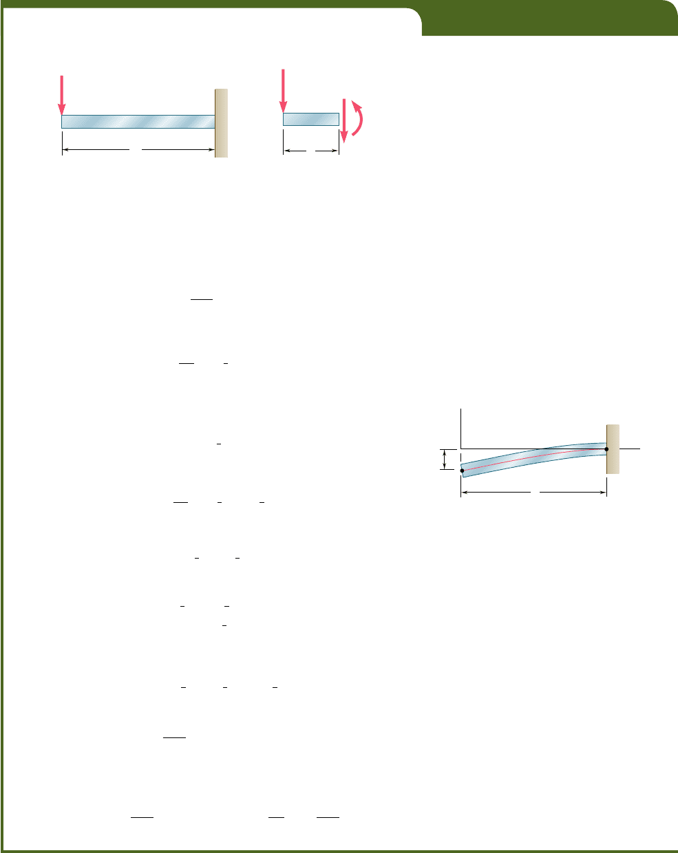
EXAMPLE 9.01
The cantilever beam AB is of uniform cross section and carries a load P
at its free end A (Fig. 9.9). Determine the equation of the elastic curve
and the deflection and slope at A.
L
P
B
A
Fig. 9.9
P
V
M
A
x
C
Fig. 9.10
B
O
y
y
A
A
L
x
[x L, 0]
[x L, y 0]
Fig. 9.11
Using the free-body diagram of the portion AC of the beam
(Fig. 9.10), where C is located at a distance x from end A, we find
M 52Px (9.7)
Substituting for M into Eq. (9.4) and multiplying both members by the
constant EI, we write
EI
d
2
y
dx
2
52Px
Integrating in x, we obtain
EI
d
y
dx
52
1
2
Px
2
1 C
1
(9.8)
We now observe that at the fixed end B we have x 5 L and u 5 dyydx 5 0
(Fig. 9.11). Substituting these values into (9.8) and solving for C
1
, we
have
C
1
5
1
2
PL
2
which we carry back into (9.8):
EI
d
y
dx
52
1
2
Px
2
1
1
2
PL
2
(9.9)
Integrating both members of Eq. (9.9), we write
EI y 52
1
6
Px
3
1
1
2
PL
2
x 1 C
2
(9.10)
But, at B we have x 5 L, y 5 0. Substituting into (9.10), we have
0 52
1
6
PL
3
1
1
2
PL
3
1 C
2
C
2
52
1
3
PL
3
Carrying the value of C
2
back into Eq. (9.10), we obtain the equation of
the elastic curve:
EI y 52
1
6
Px
3
1
1
2
PL
2
x 2
1
3
PL
3
or
y 5
P
6EI
12x
3
1 3L
2
x 2 2L
3
2 (9.11)
The deflection and slope at A are obtained by letting x 5 0 in Eqs.
(9.11) and (9.9). We find
y
A
52
PL
3
3EI
andu
A
5 a
d
y
dx
b
A
5
PL
2
2EI
bee80288_ch09_548-629.indd Page 555 10/30/10 11:17:16 PM user-f499bee80288_ch09_548-629.indd Page 555 10/30/10 11:17:16 PM user-f499 /Users/user-f499/Desktop/Temp Work/Don't Delete Job/MHDQ251:Beer:201/ch09/Users/user-f499/Desktop/Temp Work/Don't Delete Job/MHDQ251:Beer:201/ch09
Apago PDF Enhancer
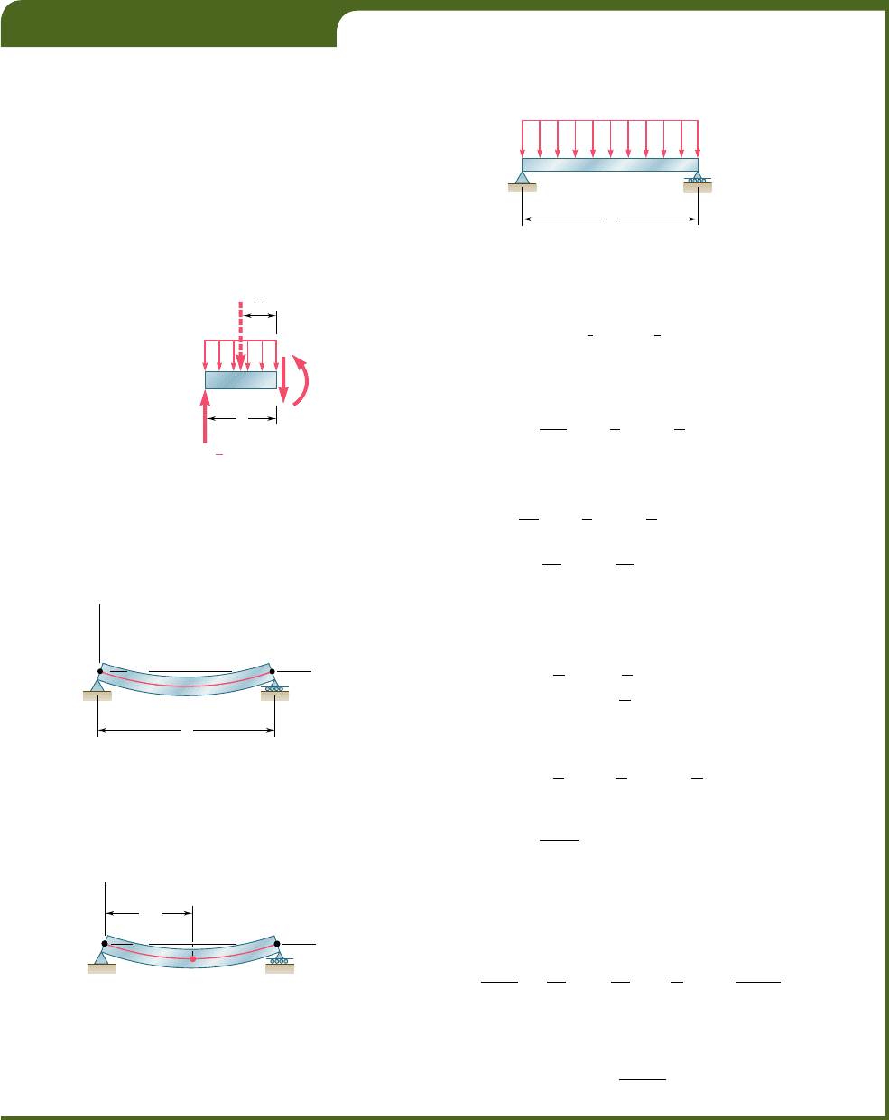
EXAMPLE 9.02
The simply supported prismatic beam AB carries a uniformly distributed
load w per unit length (Fig. 9.12). Determine the equation of the elastic
curve and the maximum deflection of the beam.
556
A
2
x
D
M
V
wx
R
A
wL
x
2
1
Fig. 9.13
B
w
A
L
Fig. 9.12
B
A
L
y
x
x 0, y 0 x L, y
0
[[
[[
Fig. 9.14
B
C
L/2
A
y
x
Fig. 9.15
Drawing the free-body diagram of the portion AD of the beam
(Fig. 9.13) and taking moments about D, we find that
M 5
1
2
wL x 2
1
2
wx
2
(9.12)
Substituting for M into Eq. (9.4) and multiplying both members of this
equation by the constant EI, we write
EI
d
2
y
dx
2
52
1
2
wx
2
1
1
2
wL x
(9.13)
Integrating twice in x, we have
EI
d
y
dx
52
1
6
wx
3
1
1
4
wL x
2
1 C
1
(9.14)
EI y 52
1
24
wx
4
1
1
12
wL x
3
1 C
1
x 1 C
2
(9.15)
Observing that y 5 0 at both ends of the beam (Fig. 9.14), we first let
x 5 0 and y 5 0 in Eq. (9.15) and obtain C
2
5 0. We then make x 5 L
and y 5 0 in the same equation and write
0 52
1
2
4
wL
4
1
1
1
2
wL
4
1 C
1
L
C
1
52
1
2
4
wL
3
Carrying the values of C
1
and C
2
back into Eq. (9.15), we obtain the
equation of the elastic curve:
EI y 52
1
24
wx
4
1
1
12
wL x
3
2
1
24
wL
3
x
or
y 5
w
24E
I
12x
4
1 2Lx
3
2 L
3
x2 (9.16)
Substituting into Eq. (9.14) the value obtained for C
1
, we check
that the slope of the beam is zero for x 5 Ly2 and that the elastic curve
has a minimum at the midpoint C of the beam (Fig. 9.15). Letting x 5
Ly2 in Eq. (9.16), we have
y
C
5
w
24EI
a
2
L
4
16
1 2L
L
3
8
2 L
3
L
2
b
52
5wL
4
384EI
The maximum deflection or, more precisely, the maximum absolute value
of the deflection, is thus
0y 0
max
5
5wL
4
384EI
bee80288_ch09_548-629.indd Page 556 10/30/10 11:17:23 PM user-f499bee80288_ch09_548-629.indd Page 556 10/30/10 11:17:23 PM user-f499 /Users/user-f499/Desktop/Temp Work/Don't Delete Job/MHDQ251:Beer:201/ch09/Users/user-f499/Desktop/Temp Work/Don't Delete Job/MHDQ251:Beer:201/ch09
