Beer F.P., Johnston E.R., DeWolf J.T., Mazurek D.F. Mechanics of Materials
Подождите немного. Документ загружается.

Apago PDF Enhancer
567
Problems
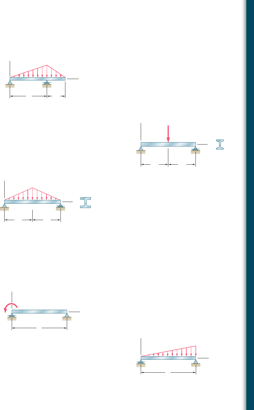
9.8 For the beam and loading shown, determine (a) the equation of
the elastic curve for portion AB of the beam, (b) the deflection at
midspan, (c) the slope at B.
9.11 (a) Determine the location and magnitude of the maximum deflec-
tion of beam AB. (b) Assuming that beam AB is a W360 3 64, L 5
3.5 m, and E 5 200 GPa, calculate the maximum allowable value of
the applied moment M
0
if the maximum deflection is not to exceed
1 mm.
B
C
A
LL/2
x
y
w
0
Fig. P9.8
9.9 Knowing that beam AB is an S200 3 34 rolled shape and that P 5
60 kN, L 5 2 m, and E 5 200 GPa, determine (a) the slope at A,
(b) the deflection at C.
9.10 Knowing that beam AB is a W10 3 33 rolled shape and that w
0
5
3 kips/ft, L 5 12 ft, and E 5 29 3 10
6
psi, determine (a) the slope
at A, (b) the deflection at C.
y
A
L/2
L/2
x
B
C
P
S
Fig. P9.9
A
C
x
B
y
w
0
W
L/2 L/2
Fig. P9.10
9.12 For the beam and loading shown, (a) express the magnitude and
location of the maximum deflection in terms of w
0
, L, E, and I.
(b) Calculate the value of the maximum deflection, assuming that
beam AB is a W18 3 50 rolled shape and that w
0
5 4.5 kips/ft,
L 5 18 ft, and E 5 29 3 10
6
psi.
x
y
A
L
B
M
0
Fig. P9.11
x
y
A
L
B
w
0
Fig. P9.12
bee80288_ch09_548-629.indd Page 567 11/18/10 8:56:25 PM user-f499bee80288_ch09_548-629.indd Page 567 11/18/10 8:56:25 PM user-f499 /Users/user-f499/Desktop/Temp Work/Don't Delete Job/MHDQ251:Beer:201/ch09/Users/user-f499/Desktop/Temp Work/Don't Delete Job/MHDQ251:Beer:201/ch09
Apago PDF Enhancer
568
Defl ection of Beams
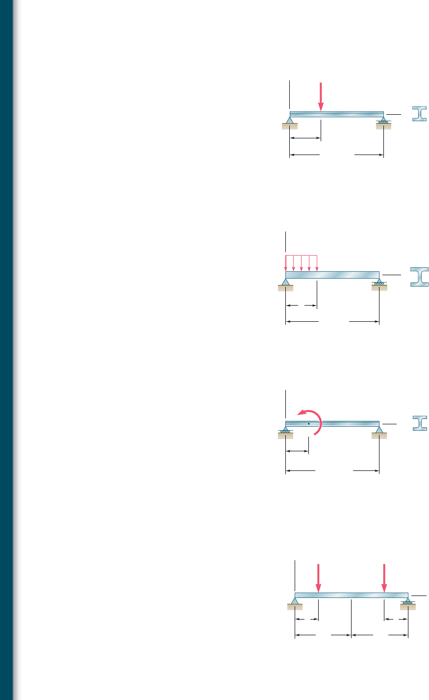
9.13 For the beam and loading shown, determine the deflection at point
C. Use E 5 29 3 10
6
psi.
x
y
A
L 15 ft
W14 30
a 5 ft
B
C
P 35 kips
Fig. P9.13
9.14 For the beam and loading shown, knowing that a 5 2 m, w 5
50 kN/m, and E 5 200 GPa, determine (a) the slope at support A,
(b) the deflection at point C.
Fig. P9.14
y
w
C
B
x
A
a
L 6 m
W310 38.7
9.15 For the beam and loading shown, determine the deflection at point
C. Use E 5 200 GPa.
Fig. P9.15
x
y
A
L 4.8 m
W200 35.9
a 1.2 m
B
C
M
0
60 kN · m
9.16 Knowing that beam AE is an S200 3 27.4 rolled shape and that
P 5 17.5 kN, L 5 2.5 m, a 5 0.8 m and E 5 200 GPa, determine
(a) the equation of the elastic curve for portion BD, (b) the deflec-
tion at the center C of the beam.
Fig. P9.16
y
E
x
A
aa
BC D
L/2L/2
PP
bee80288_ch09_548-629.indd Page 568 11/18/10 8:56:40 PM user-f499bee80288_ch09_548-629.indd Page 568 11/18/10 8:56:40 PM user-f499 /Users/user-f499/Desktop/Temp Work/Don't Delete Job/MHDQ251:Beer:201/ch09/Users/user-f499/Desktop/Temp Work/Don't Delete Job/MHDQ251:Beer:201/ch09
Apago PDF Enhancer
569
Problems
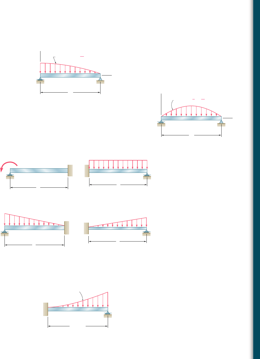
9.17 For the beam and loading shown, determine (a) the equation of
the elastic curve, (b) the slope at end A, (c) the deflection at the
midpoint of the span.
Fig. P9.17
x
y
A
L
B
w w
0
[]
1
x
2
L
2
9.18 For the beam and loading shown, determine (a) the equation of
the elastic curve, (b) the slope at end A, (c) the deflection at the
midpoint of the span.
9.19 through 9.22 For the beam and loading shown, determine the
reaction at the roller support.
Fig. P9.18
x
y
A
L
B
w 4w
0[]
x
L
x
2
L
2
L
A
B
M
0
Fig. P9.19
B
A
w
L
Fig. P9.20
B
A
w
0
L
Fig. P9.22
B
A
w
0
L
Fig. P9.21
9.23 For the beam shown, determine the reaction at the roller support
when w
0
5 15 kN/m.
Fig. P9.23
L 3 m
w
0
A
B
w w
0
(x/L)
2
bee80288_ch09_548-629.indd Page 569 10/30/10 11:19:25 PM user-f499bee80288_ch09_548-629.indd Page 569 10/30/10 11:19:25 PM user-f499 /Users/user-f499/Desktop/Temp Work/Don't Delete Job/MHDQ251:Beer:201/ch09/Users/user-f499/Desktop/Temp Work/Don't Delete Job/MHDQ251:Beer:201/ch09
Apago PDF Enhancer
570
Defl ection of Beams
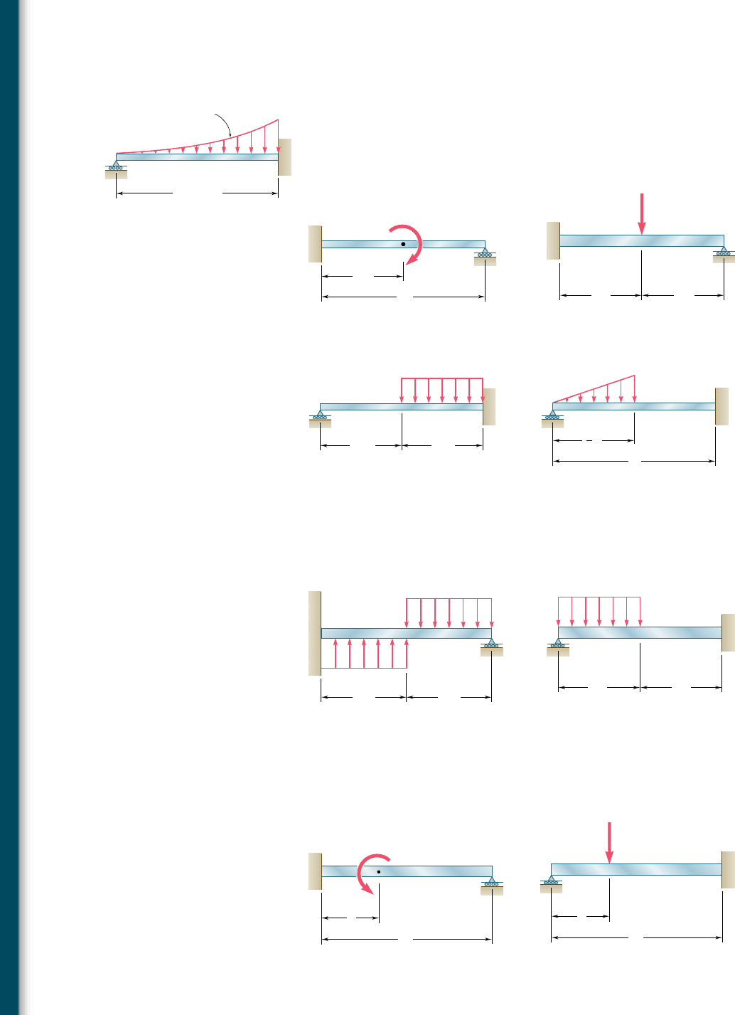
9.24 For the beam shown, determine the reaction at the roller support
when w
0
5 6 kips/ft.
9.25 through 9.28 Determine the reaction at the roller support
and draw the bending moment diagram for the beam and loading
shown.
B
L 12 ft
w w
0
(x/L)
2
A
w
0
Fig. P9.24
Fig. P9.25
B
A
L/2
C
L
M
0
Fig. P9.26
P
A
C
B
L/2 L/2
Fig. P9.27
B
C
w
A
L/2 L/2
Fig. P9.28
B
C
w
0
1
2
A
L
L
9.29 and 9.30 Determine the reaction at the roller support and the
deflection at point C.
B
C
w
w
A
L/2 L/2
Fig. P9.29
A
L/2 L/2
CB
w
Fig. P9.30
9.31 and 9.32 Determine the reaction at the roller support and the
deflection at point D if a is equal to Ly3.
B
A
a
L
D
M
0
Fig. P9.31 Fig. P9.32
B
A
D
a
L
P
bee80288_ch09_548-629.indd Page 570 10/30/10 11:19:40 PM user-f499bee80288_ch09_548-629.indd Page 570 10/30/10 11:19:40 PM user-f499 /Users/user-f499/Desktop/Temp Work/Don't Delete Job/MHDQ251:Beer:201/ch09/Users/user-f499/Desktop/Temp Work/Don't Delete Job/MHDQ251:Beer:201/ch09
Apago PDF Enhancer
9.33 and 9.34 Determine the reaction at A and draw the bending
moment diagram for the beam and loading shown.
571
Fig. P9.33
B
A
C
L/2 L/2
w
0
B
AC
P
L/2 L/2
Fig. P9.34
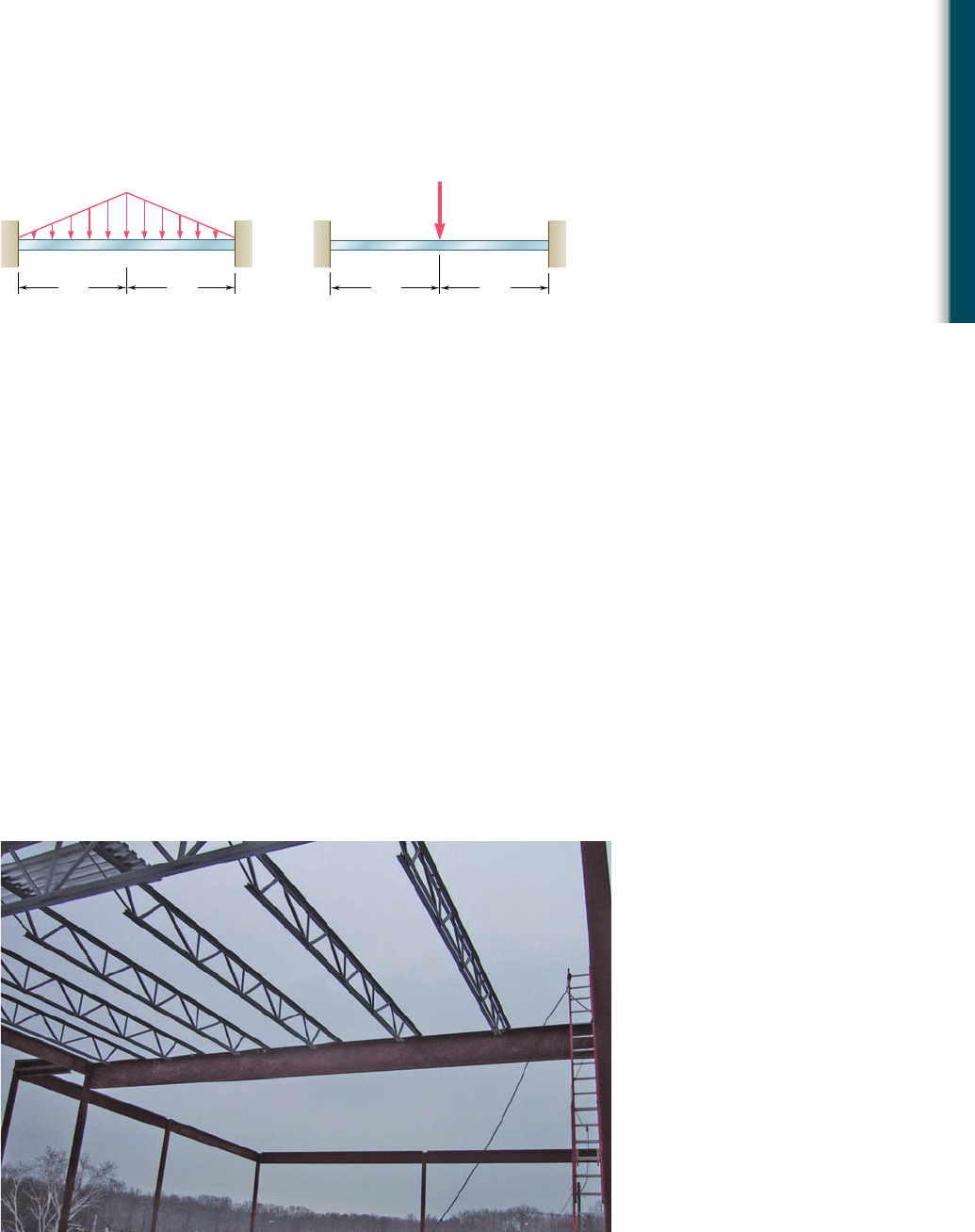
Photo 9.2 In this roof structure, each of the joists applies a concentrated load to the
beam that supports it.
9.6 Using Singularity Functions to Determine
the Slope and Defl ection of a Beam
*9.6 USING SINGULARITY FUNCTIONS TO DETERMINE
THE SLOPE AND DEFLECTION OF A BEAM
Reviewing the work done so far in this chapter, we note that the inte-
gration method provides a convenient and effective way of determining
the slope and deflection at any point of a prismatic beam, as long as
the bending moment can be represented by a single analytical function
M(x). However, when the loading of the beam is such that two different
functions are needed to represent the bending moment over the entire
length of the beam, as in Example 9.03 (Fig. 9.16), four constants of
integration are required, and an equal number of equations, expressing
continuity conditions at point D, as well as boundary conditions at the
supports A and B, must be used to determine these constants. If three
or more functions were needed to represent the bending moment,
additional constants and a corresponding number of additional equa-
tions would be required, resulting in rather lengthy computations. Such
would be the case for the beam shown in Photo 9.2. In this section
these computations will be simplified through the use of the singularity
functions discussed in Sec. 5.5.
bee80288_ch09_548-629.indd Page 571 10/30/10 11:20:00 PM user-f499bee80288_ch09_548-629.indd Page 571 10/30/10 11:20:00 PM user-f499 /Users/user-f499/Desktop/Temp Work/Don't Delete Job/MHDQ251:Beer:201/ch09/Users/user-f499/Desktop/Temp Work/Don't Delete Job/MHDQ251:Beer:201/ch09
Apago PDF Enhancer
572
Defl ection of Beams
Let us consider again the beam and loading of Example 9.03
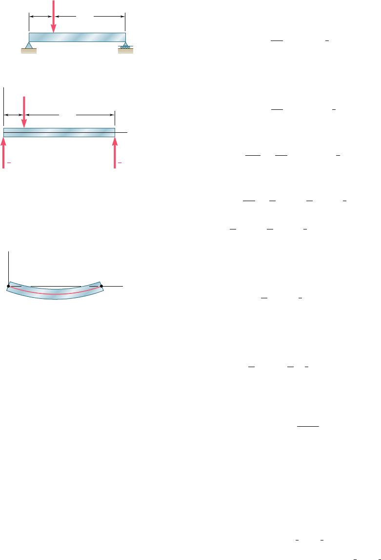
(Fig. 9.16) and draw the free-body diagram of that beam (Fig. 9.27).
Using the appropriate singularity function, as explained in Sec. 5.5,
to represent the contribution to the shear of the concentrated load
P, we write
V1x25
3
P
4
2 PHx 2
1
4
LI
0
Integrating in x and recalling from Sec. 5.5 that in the absence of
any concentrated couple, the expression obtained for the bending
moment will not contain any constant term, we have
M1x25
3
P
4
x 2 PHx 2
1
4
L
I
(9.44)
Substituting for M(x) from (9.44) into Eq. (9.4), we write
EI
d
2
y
d
x
2
5
3P
4
x 2 PHx 2
1
4
L
I
(9.45)
and, integrating in x,
EI u 5 EI
d
y
d
x
5
3
8
Px
2
2
1
2
PHx 2
1
4
LI
2
1 C
1
(9.46)
EI y 5
1
8
Px
3
2
1
6
PHx 2
1
4
LI
3
1 C
1
x 1 C
2
(9.47)†
The constants C
1
and C
2
can be determined from the boundary
con ditions shown in Fig. 9.28. Letting x 5 0, y 5 0 in Eq. (9.47),
we have
0 5 0 2
1
6
PH0 2
1
4
LI
3
1 0 1 C
2
which reduces to C
2
5 0, since any bracket containing a negative
quantity is equal to zero. Letting now x 5 L, y 5 0, and C
2
5 0 in
Eq. (9.47), we write
0 5
1
8
PL
3
2
1
6
PH
3
4
LI
3
1 C
1
L
Since the quantity between brackets is positive, the brackets can be
replaced by ordinary parentheses. Solving for C
1
, we have
C
1
52
7PL
2
128
We check that the expressions obtained for the constants C
1
and C
2
are the same that were found earlier in Sec. 9.3. But the
need for additional constants C
3
and C
4
has now been eliminated,
and we do not have to write equations expressing that the slope and
the deflection are continuous at point D.
P
B
D
A
3L/4
L/4
Fig. 9.16 (repeated)
†The continuity conditions for the slope and deflection at D are “built-in” in Eqs. (9.46)
and (9.47). Indeed, the difference between the expressions for the slope u
1
in AD and the
slope u
2
in DB is represented by the term 2
1
2
P
H
x 2
1
4
L
I
2
in Eq. (9.46), and this term is
equal to zero at D. Similarly, the difference between the expressions for the deflection y
1
in AD and the deflection y
2
in DB is represented by the term 2
1
6
P
H
x 2
1
4
L
I
3
in Eq. (9.47),
and this term is also equal to zero at D.
B
A
y
x
x 0, y 0
[]
x L, y 0
[]
Fig. 9.28 Boundary conditions for
beam of Fig. 9.16.
A
D
B
x
y
P
L/4
3L/4
3
4
P
1
4
P
Fig. 9.27 Free-body diagram for
beam of Fig. 9.16.
bee80288_ch09_548-629.indd Page 572 10/30/10 11:20:08 PM user-f499bee80288_ch09_548-629.indd Page 572 10/30/10 11:20:08 PM user-f499 /Users/user-f499/Desktop/Temp Work/Don't Delete Job/MHDQ251:Beer:201/ch09/Users/user-f499/Desktop/Temp Work/Don't Delete Job/MHDQ251:Beer:201/ch09
Apago PDF Enhancer
573
EXAMPLE 9.06
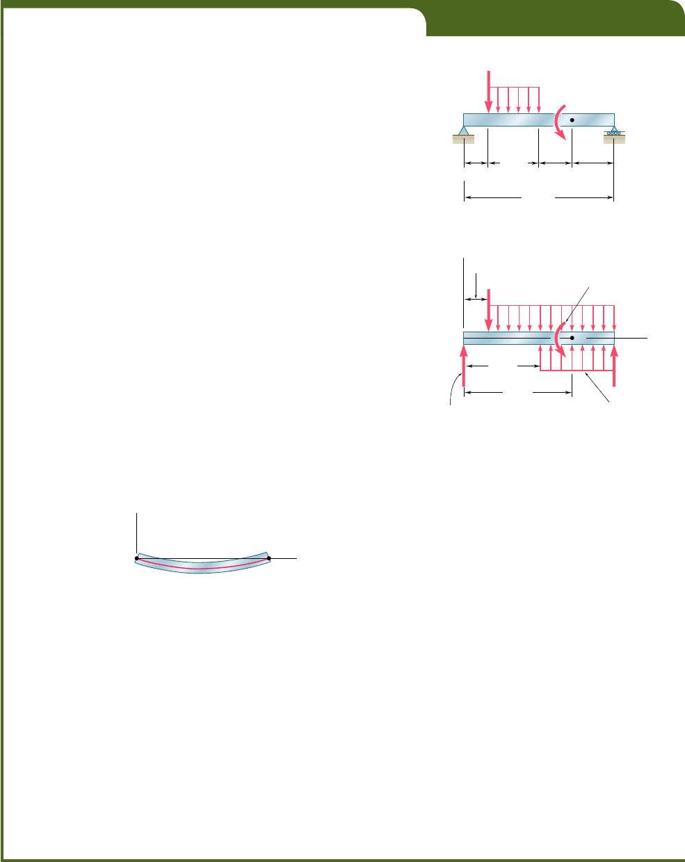
For the beam and loading shown (Fig. 9.29a) and using singularity func-
tions, (a) express the slope and deflection as functions of the distance x
from the support at A, (b) determine the deflection at the midpoint D. Use
E 5 200 GPa and I 5 6.87 3 10
26
m
4
.
(a) We note that the beam is loaded and supported in the same
manner as the beam of Example 5.05. Referring to that example, we recall
that the given distributed loading was replaced by the two equivalent
open-ended loadings shown in Fig. 9.29b and that the following expres-
sions were obtained for the shear and bending moment:
V1x2521.5
H
x 2 0.6
I
1
1 1.5
H
x 2 1.8
I
1
1 2.6 2 1.2
H
x 2 0.6
I
0
M1x2520.75
H
x 2 0.6
I
2
1 0.75
H
x 2 1.8
I
2
1 2.6x 2 1.2
H
x 2 0.6
I
1
2 1.44
H
x 2 2.6
I
0
Integrating the last expression twice, we obtain
EIu 520.25
H
x 2 0.6
I
3
1 0.25
H
x 2 1.8
I
3
1 1.3x
2
2 0.6
H
x 2 0.6
I
2
2 1.44
H
x 2 2.6
I
1
1 C
1
(9.48)
EIy 520.0625
H
x 2 0.6
I
4
1 0.0625
H
x 2 1.8
I
4
1 0.4333x
3
2 0.2
H
x 2 0.6
I
3
2 0.72
H
x 2 2.6
I
2
1 C
1
x 1 C
2
(9.49)
The constants C
1
and C
2
can be determined from the boundary
conditions shown in Fig. 9.30. Letting x 5 0, y 5 0 in Eq. (9.49) and
noting that all the brackets contain negative quantities and, therefore, are
equal to zero, we conclude that C
2
5 0. Letting now x 5 3.6, y 5 0, and
C
2
5 0 in Eq. (9.49), we write
0 520.0625
H
3.0
I
4
1 0.0625
H
1.8
I
4
1 0.433313.62
3
2 0.2
H
3.0
I
3
2 0.72
H
1.0
I
2
1 C
1
13.621 0
Since all the quantities between brackets are positive, the brackets can be
replaced by ordinary parentheses. Solving for C
1
, we find C
1
5 22.692.
B
B
w
0
1.5 kN/m
w
w
0
1.5 kN/m
P 1.2 kN
P 1.2 kN
B
A
y
2.6 kN
w
0
1.5 kN/m
M
0
1.44 kN · m
M
0
1.44 kN · m
A
C
D
E
xAE
C
D
(a)
(b)
0.6 m
1.2 m
3.6 m
0.8 m 1.0 m
0.6 m
2.6 m
1.8 m
E
E
Fig. 9.29
B
A
y
x
[x 0, y 0] [x 3.6, y 0]
Fig. 9.30
(b) Substituting for C
1
and C
2
into Eq. (9.49) and making x 5 x
D
5
1.8 m, we find that the deflection at point D is defined by the relation
EIy
D
520.0625
H
1.2
I
4
1 0.0625
H
0
I
4
1 0.433311.82
3
2 0.2
H
1.2
I
3
2 0.72
H
20.8
I
2
2 2.69211.82
The last bracket contains a negative quantity and, therefore, is equal to
zero. All the other brackets contain positive quantities and can be replaced
by ordinary parentheses. We have
EIy
D
520.062511.22
4
1 0.0625102
4
1 0.4333
1
1.8
2
3
2 0.2
1
1.2
2
3
2 0 2 2.692
1
1.8
2
522.794
Recalling the given numerical values of E and I, we write
1200 GPa216.87 3 10
2
6
m
4
2y
D
522.794 kN ? m
3
y
D
5213.64 3 10
2
3
m 522.03 mm
bee80288_ch09_548-629.indd Page 573 11/18/10 8:56:49 PM user-f499bee80288_ch09_548-629.indd Page 573 11/18/10 8:56:49 PM user-f499 /Users/user-f499/Desktop/Temp Work/Don't Delete Job/MHDQ251:Beer:201/ch09/Users/user-f499/Desktop/Temp Work/Don't Delete Job/MHDQ251:Beer:201/ch09
Apago PDF Enhancer
574
SAMPLE PROBLEM 9.4
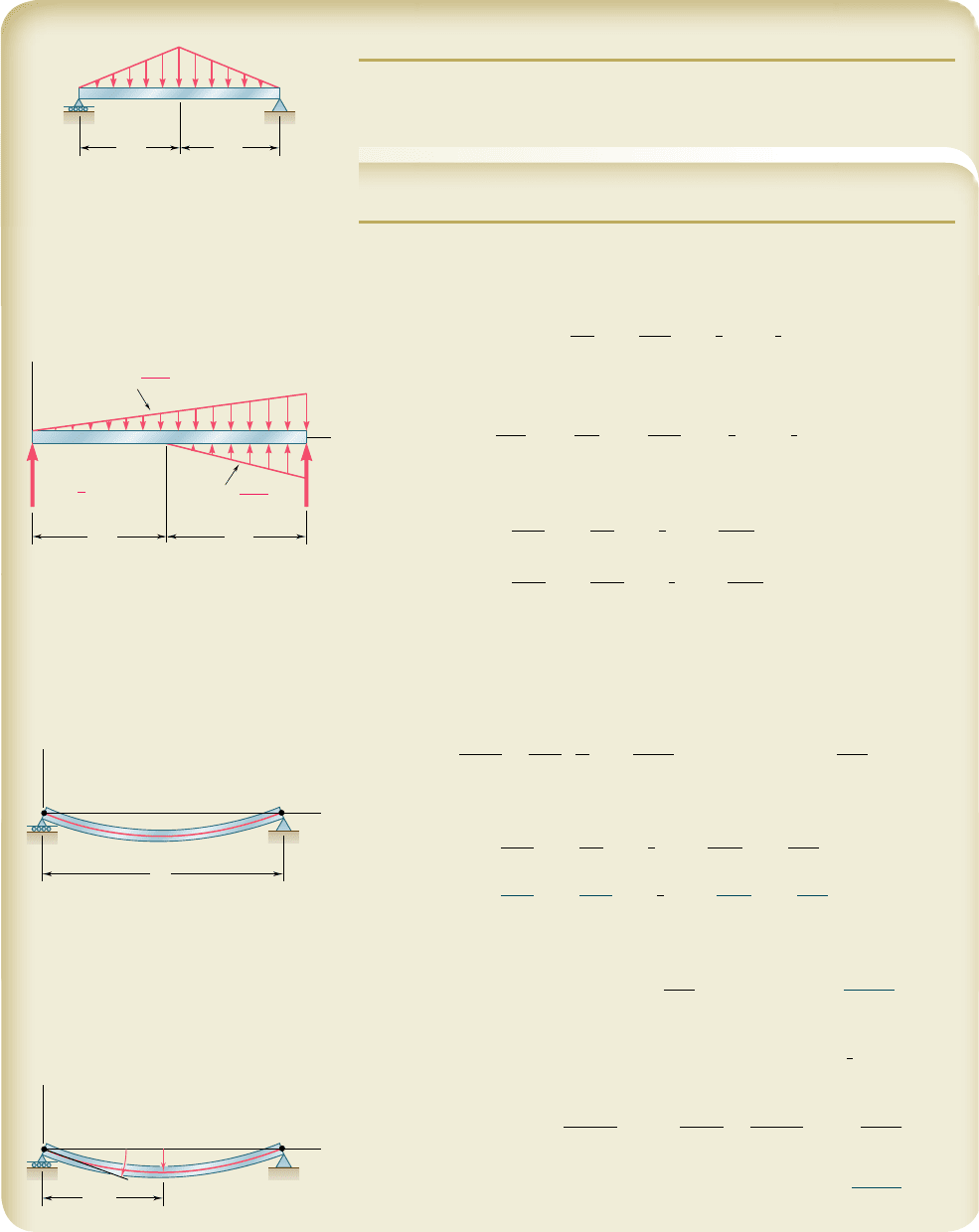
For the prismatic beam and loading shown, determine (a) the equation of
the elastic curve, (b) the slope at A, (c) the maximum deflection.
SOLUTION
Bending Moment. The equation defining the bending moment of the
beam was obtained in Sample Prob. 5.9. Using the modified loading diagram
shown, we had [Eq. (3)]:
M1x252
w
0
3L
x
3
1
2
w
0
3L
Hx 2
1
2
LI
3
1
1
4
w
0
Lx
a. Equation of the Elastic Curve. Using Eq. (9.4), we write
EI
d
2
y
dx
2
52
w
0
3L
x
3
1
2w
0
3L
Hx 2
1
2
LI
3
1
1
4
w
0
Lx
(1)
and, integrating twice in x,
EI u 52
w
0
12L
x
4
1
w
0
6L
Hx 2
1
2
LI
4
1
w
0
L
8
x
2
1 C
1
(2)
EI y 52
w
0
60L
x
5
1
w
0
30L
Hx 2
1
2
LI
5
1
w
0
L
24
x
3
1 C
1
x 1 C
2
(3)
Boundary Conditions.
[x 5 0, y 5 0]: Using Eq. (3) and noting that each bracket H I con-
tains a negative quantity and, thus, is equal to zero, we find C
2
5 0.
[x 5 L, y 5 0]: Again using Eq. (3), we write
0 52
w
0
L
4
60
1
w
0
30L
a
L
2
b
5
1
w
0
L
4
24
1 C
1
L
C
1
52
5
1
9
2
w
0
L
3
Substituting C
1
and C
2
into Eqs. (2) and (3), we have
EI u 52
w
0
12L
x
4
1
w
0
6L
Hx 2
1
2
LI
4
1
w
0
L
8
x
2
2
5
192
w
0
L
3
(4)
EI y 52
w
0
60L
x
5
1
w
0
30L
Hx 2
1
2
LI
5
1
w
0
L
24
x
3
2
5
192
w
0
L
3
x
(5) b
b. Slope at A. Substituting x 5 0 into Eq. (4), we find
EI u
A
52
5
1
9
2
w
0
L
3
u
A
5
5w
0
L
3
1
9
2E
I
c b
c. Maximum Deflection. Because of the symmetry of the supports and
loading, the maximum deflection occurs at point C, where
x
5
1
2
L. Substitut-
ing into Eq. (5), we obtain
EI y
max
5 w
0
L
4
c2
1
60
1
32
2
1 0 1
1
24
1
8
2
2
5
192
1
2
2
d52
w
0
L
4
120
y
max
5
w
0
L
4
120EI
w b
w
0
A
B
L/2 L/2
C
w
2w
0
L
k
1
A
C
R
A
R
B
x
B
L/2 L/2
4w
0
L
k
2
1
w
0
L
4
L
A
B
C
y
x
[ x 0, y 0 ][ x L, y 0 ]
L/2
A
B
C
y
x
y
max
A
bee80288_ch09_548-629.indd Page 574 11/19/10 3:17:10 PM user-f499bee80288_ch09_548-629.indd Page 574 11/19/10 3:17:10 PM user-f499 /Users/user-f499/Desktop/Temp Work/Don't Delete Job/MHDQ251:Beer:201/ch09/Users/user-f499/Desktop/Temp Work/Don't Delete Job/MHDQ251:Beer:201/ch09
Apago PDF Enhancer
575
SAMPLE PROBLEM 9.5
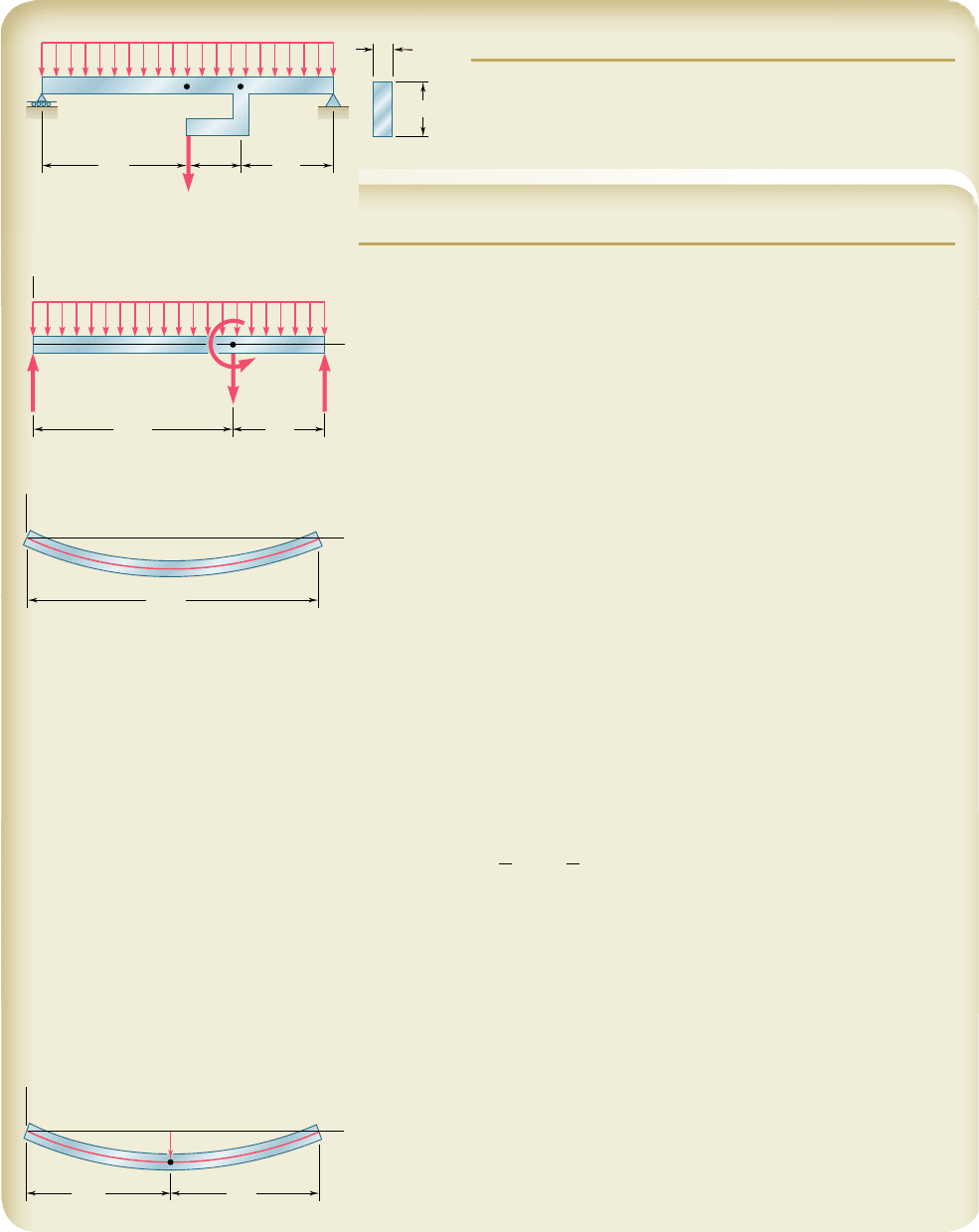
The rigid bar DEF is welded at point D to the uniform steel
beam AB. For the loading shown, determine (a) the equation
of the elastic curve of the beam, (b) the deflection at the mid-
point C of the beam. Use E 5 29 3 10
6
psi.
SOLUTION
Bending Moment. The equation defining the bending moment of the
beam was obtained in Sample Prob. 5.10. Using the modified loading dia-
gram shown and expressing x in feet, we had [Eq. (3)]:
M(x) 5 225x
2
1 480x 2 160 Hx 2 11I
1
2 480Hx 2 11I
0
lb ? ft
a. Equation of the Elastic Curve. Using Eq. (8.4), we write
EI(d
2
yydx
2
) 5 225x
2
1 480x 2 160Hx 2 11I
1
2 480Hx 2 11I
0
lb ? ft (1)
and, integrating twice in x,
EI u 5 28.333x
3
1 240x
2
2 80Hx 2 11I
2
2 480Hx 2 11I
1
1 C
1
lb ? ft
2
(2)
EI y 5 22.083x
4
1 80x
3
2 26.67Hx 2 11I
3
2 240Hx 2 11I
2
1 C
1
x 1 C
2
lb ? ft
3
(3)
Boundary Conditions.
[x 5 0, y 5 0]: Using Eq. (3) and noting that each bracket H I con-
tains a negative quantity and, thus, is equal to zero, we find C
2
5 0.
[x 5 16 ft, y 5 0]: Again using Eq. (3) and noting that each bracket con-
tains a positive quantity and, thus, can be replaced by a parenthesis, we write
0 522.083
1
16
2
4
1 80
1
16
2
3
2 26.67
1
5
2
3
2 240
1
5
2
2
1 C
1
1
16
2
C
1
5211.36 3 10
3
Substituting the values found for C
1
and C
2
into Eq. (3), we have
EI y 522.083x
4
1 80x
3
2 26.67
H
x 2 11
I
3
2 240
H
x 2 11
I
2
2 11.36 3 10
3
xl
b
? ft
3
(39) b
To determine EI, we recall that E 5 29 3 10
6
psi and compute
I 5
1
12
bh
3
5
1
12
1
1 in.
21
3 in.
2
3
5 2.25 in
4
EI 5 129 3 10
6
psi212.25 in
4
25 65.25 3 10
6
lb ? in
2
However, since all previous computations have been carried out with feet
as the unit of length, we write
EI 5
1
65.25 3 10
6
lb ? in
2
21
1 ft/12 in.
2
2
5 453.1 3 10
3
lb ? ft
2
b. Deflection at Midpoint C. Making x 5 8 ft in Eq. (39), we write
EI y
C
522.083182
4
1 80182
3
2 26.67
H
23
I
3
2 240
H
23
I
2
2 11.36 3 10
3
182
Noting that each bracket is equal to zero and substituting for EI its numeri-
cal value, we have
(453.1 3 10
3
lb ? ft
2
)y
C
5 258.45 3 10
3
lb ? ft
3
and, solving for y
C
: y
C
5 20.1290 ft y
C
5 21.548 in. b
Note that the deflection obtained is not the maximum deflection.
B
C
F E
D
A
50 lb/ft
160 lb
8 ft
3 ft
3 in.
1 in.
5 ft
B
x
D
A
w
0
50 lb/ft
w
M
D
480 lb · ft
R
A
480 lb R
B
P
160 lb
5 ft11 ft
16 ft
y
A
x
B
[ x 0, y 0 ]
[ x 16 ft, y 0 ]
8 ft 8 ft
y
A
C
x
B
y
C
bee80288_ch09_548-629.indd Page 575 11/19/10 3:17:29 PM user-f499bee80288_ch09_548-629.indd Page 575 11/19/10 3:17:29 PM user-f499 /Users/user-f499/Desktop/Temp Work/Don't Delete Job/MHDQ251:Beer:201/ch09/Users/user-f499/Desktop/Temp Work/Don't Delete Job/MHDQ251:Beer:201/ch09
Apago PDF Enhancer
576
SAMPLE PROBLEM 9.6
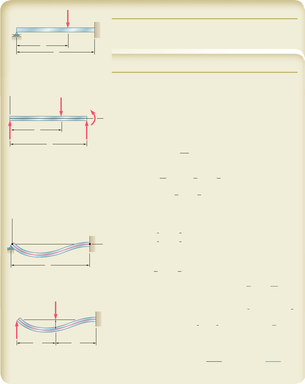
For the uniform beam ABC, (a) express the reaction at A in terms of P, L,
a, E, and I, (b) determine the reaction at A and the deflection under the
load when a 5 Ly2.
SOLUTION
Reactions. For the given vertical load P the reactions are as shown.
We note that they are statically indeterminate.
Shear and Bending Moment. Using a step function to represent the
contribution of P to the shear, we write
V1x25 R
A
2 P
H
x 2 a
I
0
Integrating in x, we obtain the bending moment:
M1x25 R
A
x 2 P
H
x 2 a
I
1
Equation of the Elastic Curve. Using Eq. (9.4), we write
EI
d
2
y
dx
2
5 R
A
x 2 PHx 2 aI
1
Integrating twice in x,
EI
d
y
dx
5 EI u 5
1
2
R
A
x
2
2
1
2
PHx 2 aI
2
1 C
1
EI y 5
1
6
R
A
x
3
2
1
6
PHx 2 aI
3
1 C
1
x 1 C
2
Boundary Conditions. Noting that the bracket
H
x 2 a
I
is equal to
zero for x 5 0, and to (L 2 a) for x 5 L, we write
3
x 5 0, y 5 0
4
:
C
2
5
0
(1)
3
x 5 L, u 5 0
4
:
1
2
R
A
L
2
2
1
2
P
1
L 2 a
2
2
1 C
1
5 0 (2)
3
x 5 L, y 5 0
4
:
1
6
R
A
L
3
2
1
6
P
1
L 2 a
2
3
1 C
1
L 1 C
2
5 0 (3)
a. Reaction at A. Multiplying Eq. (2) by L, subtracting Eq. (3) member
by member from the equation obtained, and noting that C
2
5 0, we have
1
3
R
A
L
3
2
1
6
P1L 2 a2
2
33L 2 1L 2 a245 0
R
A
5 P
a
1 2
a
L
b
2
a
1 1
a
2L
b
x b
We note that the reaction is independent of E and I.
b. Reaction at A and Deflection at B when a 5
1
2
L. Making
a
5
1
2
L
in the expression obtained for R
A
, we have
R
A
5 P
1
1 2
1
2
2
2
1
1 1
1
4
2
5 5P
y
16 R
A
5
5
16
Px b
Substituting a 5 Ly2 and R
A
5 5Py16 into Eq. (2) and solving for C
1
, we
find C
1
5 2PL
2
y32. Making x 5 Ly2, C
1
5 2PL
2
y32, and C
2
5 0 in the
expression obtained for y, we have
y
B
52
7PL
3
768EI
y
B
5
7PL
3
768EI
w b
Note that the deflection obtained is not the maximum deflection.
B
C
L
a
A
P
P
L
A
y
BC
x
a
M
C
R
C
R
A
L
C
A
y
[ x 0, y 0 ]
[ x 0, y 0 ]
[ x L, 0 ]
x
A
B
C
R
A
y
B
L/2L/2
P
bee80288_ch09_548-629.indd Page 576 10/30/10 11:20:39 PM user-f499bee80288_ch09_548-629.indd Page 576 10/30/10 11:20:39 PM user-f499 /Users/user-f499/Desktop/Temp Work/Don't Delete Job/MHDQ251:Beer:201/ch09/Users/user-f499/Desktop/Temp Work/Don't Delete Job/MHDQ251:Beer:201/ch09
