Beer F.P., Johnston E.R., DeWolf J.T., Mazurek D.F. Mechanics of Materials
Подождите немного. Документ загружается.

Apago PDF Enhancer
PROBLEMS
577
Use singularity functions to solve the following problems
and assume that the flexural rigidity EI of each beam is
constant.
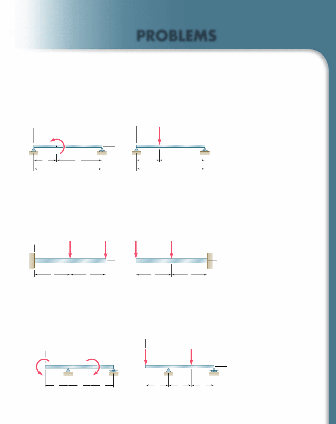
9.35 and 9.36 For the beam and loading shown, determine (a) the
equation of the elastic curve, (b) the slope at end A, (c) the deflec-
tion of point C.
M
0
x
y
B
C
A
ab
L
Fig. P9.35
x
y
B
C
A
L
ab
P
Fig. P9.36
9.37 and 9.38 For the beam and loading shown, determine (a) the
equation of the elastic curve, (b) the slope at the free end, (c) the
deflection of the free end.
AB
C
a
y
a
x
P P
Fig. P9.37
a
A
y
BC
a
x
PP
Fig. P9.38
9.39 and 9.40 For the beam and loading shown, determine (a) the
deflection at end A, (b) the deflection at point C, (c) the slope at
end D.
x
y
D
C
B
A
a
M
0
M
0
aa
Fig. P9.39
x
y
D
CB
A
aaa
P P
Fig. P9.40
bee80288_ch09_548-629.indd Page 577 10/30/10 11:20:50 PM user-f499bee80288_ch09_548-629.indd Page 577 10/30/10 11:20:50 PM user-f499 /Users/user-f499/Desktop/Temp Work/Don't Delete Job/MHDQ251:Beer:201/ch09/Users/user-f499/Desktop/Temp Work/Don't Delete Job/MHDQ251:Beer:201/ch09
Apago PDF Enhancer
578
Defl ection of Beams
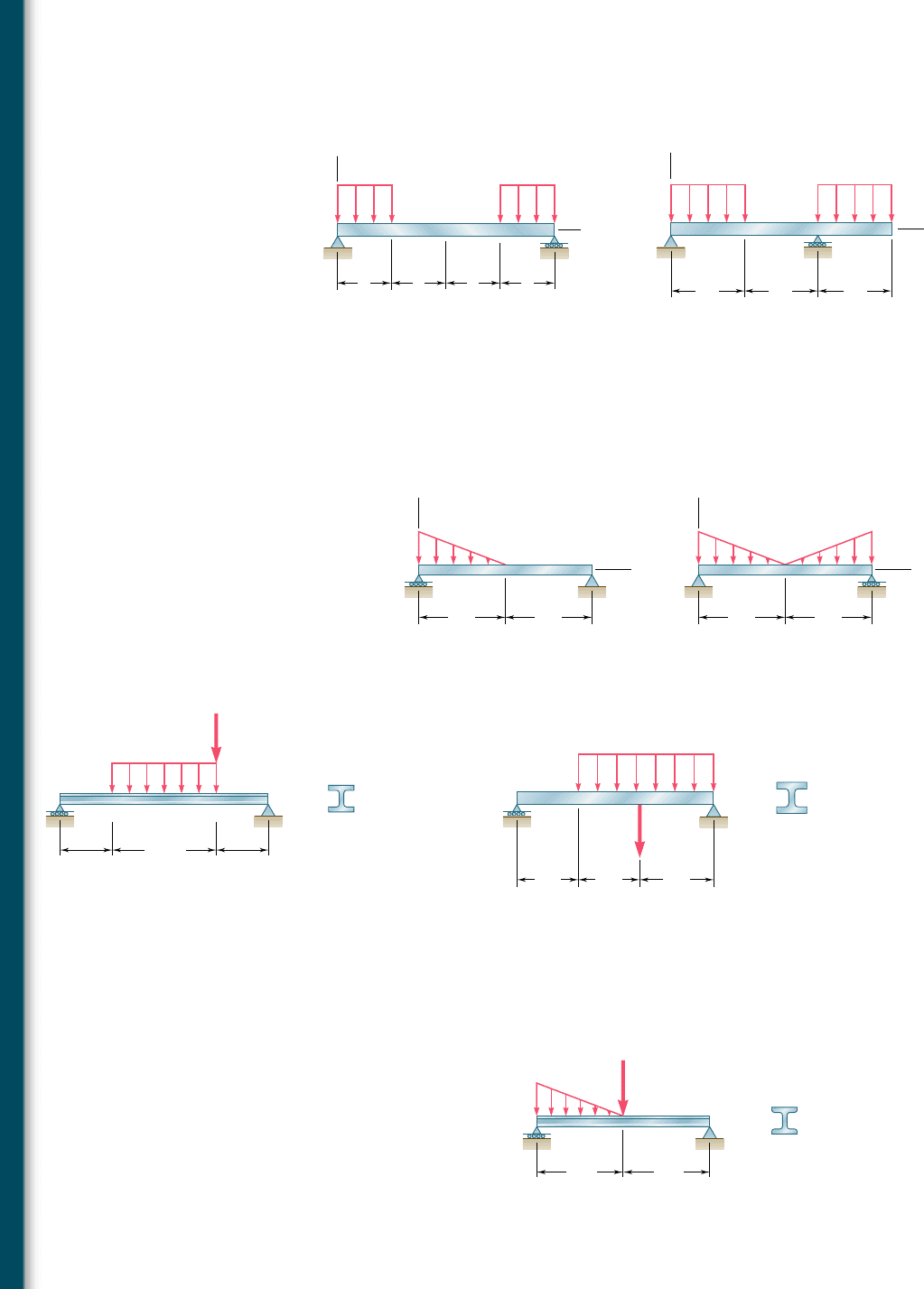
9.41 For the beam and loading shown, determine (a) the equation of
the elastic curve, (b) the deflection at the midpoint C.
C
y
x
A
B
a
aaa
w w
Fig. P9.41
L/2 L/2
B
A
y
C
D
x
L/2
w w
Fig. P9.42
9.42 For the beam and loading shown, determine (a) the equation of
the elastic curve, (b) the deflection at point B, (c) the deflection
at point D.
9.43 and 9.44 For the beam and loading shown, determine (a) the
equation of the elastic curve, (b) the deflection at the midpoint C.
x
B
C
A
w
0
L/2 L/2
y
Fig. P9.43
x
B
C
A
w
0
w
0
L/2 L/2
y
Fig. P9.44
9.45 For the beam and loading shown, determine (a) the slope at end
A, (b) the deflection at point C. Use E 5 200 GPa.
A
D
12 kN/m
CB
0.4 m 0.4 m
0.8 m
W150 13.5
20 kN
Fig. P9.45
9.46 For the beam and loading shown, determine (a) the slope at end A,
(b) the deflection at point C. Use E 5 29 3 10
6
psi.
9.47 For the beam and loading shown, determine (a) the slope at end
A, (b) the deflection at the midpoint C. Use E 5 200 GPa.
W16 57
5 ft
5 ft 6 ft
3 kips/ft
20 kips
A
D
C
B
Fig. P9.46
A
S130 15
1 m 1 m
B
C
8 kN
48 kN/m
Fig. P9.47
bee80288_ch09_548-629.indd Page 578 11/1/10 8:39:08 PM user-f499bee80288_ch09_548-629.indd Page 578 11/1/10 8:39:08 PM user-f499 /Users/user-f499/Desktop/Temp Work/Don't Delete Job/MHDQ251:Beer:201/ch09/Users/user-f499/Desktop/Temp Work/Don't Delete Job/MHDQ251:Beer:201/ch09
Apago PDF Enhancer
579
Problems
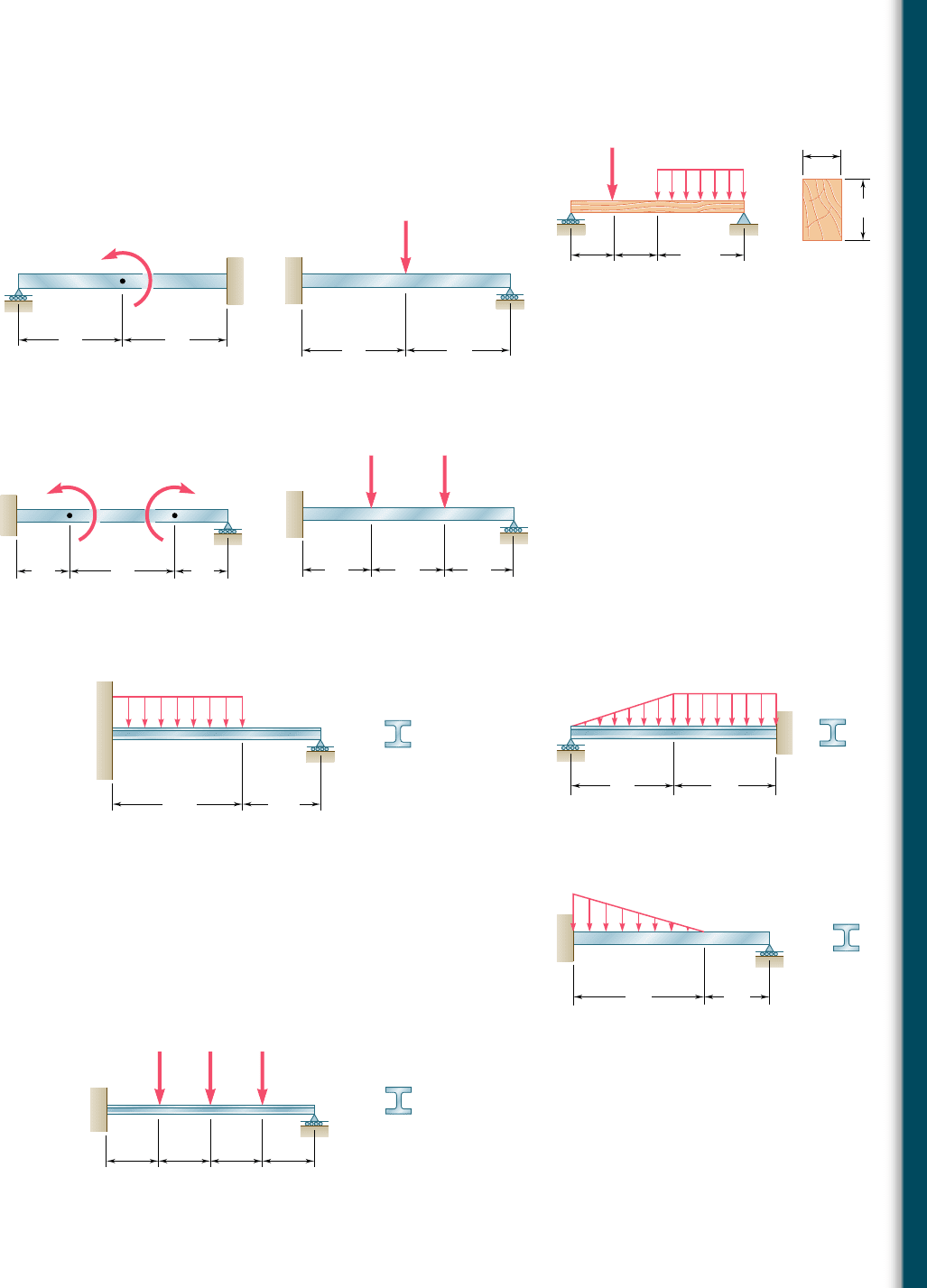
9.48 For the timber beam and loading shown, determine (a) the
slope at end A, (b) the deflection at the midpoint C. Use E 5
1.6 3 10
6
psi.
9.49 and 9.50 For the beam and loading shown, determine (a) the
reaction at the roller support, (b) the deflection at point C.
A
D
350 lb/ft
2 kips
C
B
1.75 ft 1.75 ft
3.5 ft
3.5 in.
5.5 in.
Fig. P9.48
L/2 L/2
C
A
B
M
0
Fig. P9.49
P
A
C
B
L/2 L/2
Fig. P9.50
9.51 and 9.52 For the beam and loading shown, determine (a) the
reaction at the roller support, (b) the deflection at point B.
A
B
M
0
M
0
L/4 L/2 L/4
D
C
Fig. P9.51
L/3
A B C
D
L/3 L/3
P P
Fig. P9.52
9.53 For the beam and loading shown, determine (a) the reaction at
point C, (b) the deflection at point B. Use E 5 200 GPa.
C
B
A
14 kN/m
W410 60
5 m 3 m
Fig. P9.53
9.54 For the beam and loading shown, determine (a) the reaction at
point A, (b) the deflection at point C. Use E 5 29 3 10
6
psi.
9.55 For the beam and loading shown, determine (a) the reaction at
point C, (b) the deflection at point B. Use E 5 29 3 10
6
psi.
9.56 For the beam shown and knowing that P 5 40 kN, determine
(a) the reaction at point E, (b) the deflection at point C. Use E 5
200 GPa.
B
C
2.5 kips/ft
6 ft 6 ft
A
W10 22
Fig. P9.54
W12 40
8 ft
4 ft
A
C
B
w
0
9 kips/ft
Fig. P9.55
E
0.5 m 0.5 m 0.5 m 0.5 m
B CD
P
W200 46.1
P P
A
Fig. P9.56
bee80288_ch09_548-629.indd Page 579 10/30/10 11:21:18 PM user-f499bee80288_ch09_548-629.indd Page 579 10/30/10 11:21:18 PM user-f499 /Users/user-f499/Desktop/Temp Work/Don't Delete Job/MHDQ251:Beer:201/ch09/Users/user-f499/Desktop/Temp Work/Don't Delete Job/MHDQ251:Beer:201/ch09
Apago PDF Enhancer
9.7 METHOD OF SUPERPOSITION
When a beam is subjected to several concentrated or distributed
loads, it is often found convenient to compute separately the slope
and deflection caused by each of the given loads. The slope and
deflection due to the combined loads are then obtained by applying
the principle of superposition (Sec. 2.12) and adding the values of
the slope or deflection corresponding to the various loads.
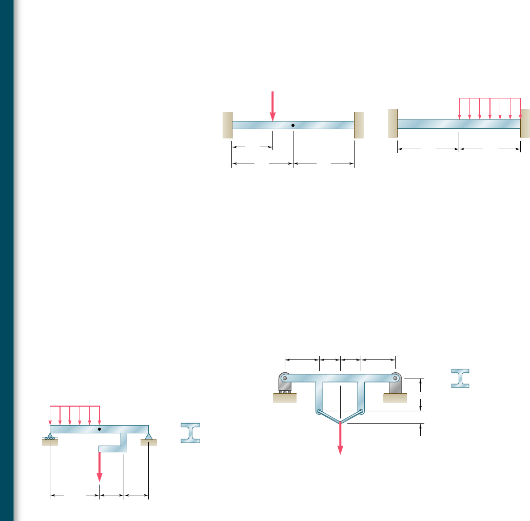
9.57 and 9.58 For the beam and loading shown, determine (a) the
reaction at point A, (b) the deflection at midpoint C.
L/2 L/2
A B CD
L/3
P
Fig. P9.57
B
AC
L/2 L/2
w
Fig. P9.58
9.59 through 9.62 For the beam and loading indicated, determine
the magnitude and location of the largest downward deflection.
9.59 Beam and loading of Prob. 9.45.
9.60 Beam and loading of Prob. 9.46.
9.61 Beam and loading of Prob. 9.47.
9.62 Beam and loading of Prob. 9.48.
9.63 The rigid bars BF and DH are welded to the rolled-steel beam AE
as shown. Determine for the loading shown (a) the deflection at
point B, (b) the deflection at midpoint C of the beam. Use E 5
200 GPa.
D
0.4 m
H
G
E
CB
F
A
W100 19.3
0.15 m
0.5 m 0.3 m 0.3 m 0.5 m
100 kN
Fig. P9.63
9.64 The rigid bar DEF is welded at point D to the rolled-steel beam
AB. For the loading shown, determine (a) the slope at point A,
(b) the deflection at midpoint C of the beam. Use E 5 200 GPa.
1.2 m
50 kN
30 kN/m
1.2 m
2.4 m
A B
C
F
D
E
W460 52
Fig. P9.64
580
Defl ection of Beams
bee80288_ch09_548-629.indd Page 580 10/30/10 11:21:39 PM user-f499bee80288_ch09_548-629.indd Page 580 10/30/10 11:21:39 PM user-f499 /Users/user-f499/Desktop/Temp Work/Don't Delete Job/MHDQ251:Beer:201/ch09/Users/user-f499/Desktop/Temp Work/Don't Delete Job/MHDQ251:Beer:201/ch09
Apago PDF Enhancer
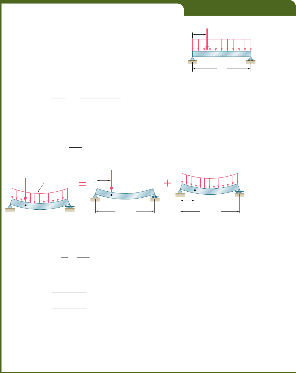
EXAMPLE 9.07
Determine the slope and deflection at D for the beam and loading
shown (Fig. 9.31), knowing that the flexural rigidity of the beam is
EI 5 100 MN ? m
2
.
The slope and deflection at any point of the beam can be obtained
by superposing the slopes and deflections caused respectively by the con-
centrated load and by the distributed load (Fig. 9.32).
Since the concentrated load in Fig. 9.32b is applied at quarter span,
we can use the results obtained for the beam and loading of Example 9.03
and write
1u
D
2
P
52
PL
2
32EI
52
1150 3 10
3
2182
2
32
1
100 3 10
6
2
523 3 10
23
rad
1y
D
2
P
52
3PL
3
256EI
52
31150 3 10
3
2182
3
256
1
100 3 10
6
2
529 3 10
23
m
529 mm
On the other hand, recalling the equation of the elastic curve obtained
for a uniformly distributed load in Example 9.02, we express the deflec-
tion in Fig. 9.32c as
y
5
w
24E
I
12x
4
1 2L x
3
2 L
3
x2 (9.50)
A
D
B
150 kN
20 kN/m
2 m
8 m
Fig. 9.31
D
x 2 m
L 8 m
(c)
B
A
w 20 kN/m
Fig. 9.32
D
20 kN/m
150 kN
B
A
(a)
2 m
D
B
A
L 8 m
P 150 kN
(b)
and, differentiating with respect to x,
u 5
d
y
dx
5
w
24EI
124x
3
1 6L x
2
2 L
3
2 (9.51)
Making w 5 20 kN/m, x 5 2 m, and L 5 8 m in Eqs. (9.51) and (9.50),
we obtain
1u
D
2
w
5
20 3 10
3
241100 3 10
6
2
123522 522.93 3 10
23
rad
1y
D
2
w
5
20 3 10
3
241100 3 10
6
2
129122 527.60 3 10
23
m
52
7.
60 mm
Combining the slopes and deflections produced by the concentrated and
the distributed loads, we have
u
D
5 1u
D
2
P
1 1u
D
2
w
523 3 10
23
2 2.93 3 10
23
525
.
93 3 10
23
r
ad
y
D
5 1y
D
2
P
1 1y
D
2
w
529 mm 2 7.60 mm 5216.60 mm
581
bee80288_ch09_548-629.indd Page 581 10/30/10 11:21:48 PM user-f499bee80288_ch09_548-629.indd Page 581 10/30/10 11:21:48 PM user-f499 /Users/user-f499/Desktop/Temp Work/Don't Delete Job/MHDQ251:Beer:201/ch09/Users/user-f499/Desktop/Temp Work/Don't Delete Job/MHDQ251:Beer:201/ch09
Apago PDF Enhancer
582
Defl ection of Beams
To facilitate the task of practicing engineers, most structural
and mechanical engineering handbooks include tables giving the
deflections and slopes of beams for various loadings and types of
support. Such a table will be found in Appendix D. We note that the
slope and deflection of the beam of Fig. 9.31 could have been deter-
mined from that table. Indeed, using the information given under
cases 5 and 6, we could have expressed the deflection of the beam
for any value x # Ly4. Taking the derivative of the expression
obtained in this way would have yielded the slope of the beam over
the same interval. We also note that the slope at both ends of the
beam can be obtained by simply adding the corresponding values
given in the table. However, the maximum deflection of the beam
of Fig. 9.31 cannot be obtained by adding the maximum deflections
of cases 5 and 6, since these deflections occur at different points of
the beam.†
9.8 APPLICATION OF SUPERPOSITION TO STATICALLY
INDETERMINATE BEAMS
We often find it convenient to use the method of superposition to
determine the reactions at the supports of a statically indeterminate
beam. Considering first the case of a beam indeterminate to the first
degree (cf. Sec. 9.5), such as the beam shown in Photo 9.3, we follow
the approach described in Sec. 2.9. We designate one of the reac-
tions as redundant and eliminate or modify accordingly the corre-
sponding support. The redundant reaction is then treated as an
unknown load that, together with the other loads, must produce
deformations that are compatible with the original supports. The
slope or deflection at the point where the support has been modified
or eliminated is obtained by computing separately the deformations
caused by the given loads and by the redundant reaction, and by
superposing the results obtained. Once the reactions at the supports
have been found, the slope and deflection can be determined in the
usual way at any other point of the beam.
†An approximate value of the maximum deflection of the beam can be obtained by plot-
ting the values of y corresponding to various values of x. The determination of the exact
location and magnitude of the maximum deflection would require setting equal to zero
the expression obtained for the slope of the beam and solving this equation for x.
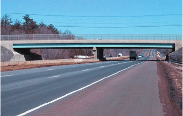
Photo 9.3 The continuous beams supporting
this highway overpass have three supports and
are thus statically indeterminate.
bee80288_ch09_548-629.indd Page 582 10/30/10 11:21:54 PM user-f499bee80288_ch09_548-629.indd Page 582 10/30/10 11:21:54 PM user-f499 /Users/user-f499/Desktop/Temp Work/Don't Delete Job/MHDQ251:Beer:201/ch09/Users/user-f499/Desktop/Temp Work/Don't Delete Job/MHDQ251:Beer:201/ch09
Apago PDF Enhancer
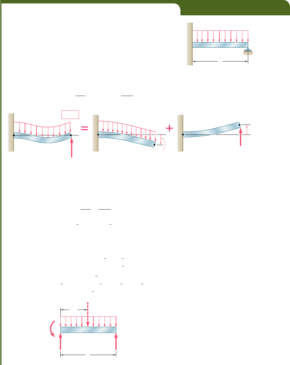
EXAMPLE 9.08
Determine the reactions at the supports for the prismatic beam and loading
shown in Fig. 9.33. (This is the same beam and loading as in Example 9.05
of Sec. 9.5.)
We consider the reaction at B as redundant and release the beam
from the support. The reaction R
B
is now considered as an unknown load
(Fig. 9.34a) and will be determined from the condition that the deflection
of the beam at B must be zero. The solution is carried out by considering
separately the deflection (y
B
)
w
caused at B by the uniformly distributed
load w (Fig. 9.34b) and the deflection (y
B
)
R
produced at the same point
by the redundant reaction R
B
(Fig. 9.34c).
From the table of Appendix D (cases 2 and 1), we find that
1y
B
2
w
52
wL
4
8EI
1y
B
2
R
51
R
B
L
3
3EI
Writing that the deflection at B is the sum of these two quantities and
that it must be zero, we have
y
B
5 1y
B
2
w
1 1y
B
2
R
5 0
y
B
52
wL
4
8EI
1
R
B
L
3
3EI
5 0
and, solving for R
B
, R
B
5
3
8
wLR
B
5
3
8
wLx
Drawing the free-body diagram of the beam (Fig. 9.35) and writing
the corresponding equilibrium equations, we have
1xgF
y
5 0: R
A
1 R
B
2 wL 5
0
(9.52)
R
A
5 wL 2 R
B
5 wL 2
3
8
wL 5
5
8
wL
R
A
5
5
8
wL
x
1
l
gM
A
5 0: M
A
1 R
B
L 2
1
wL
21
1
2
L
2
5 0 (9.53)
M
A
5
1
2
wL
2
2 R
B
L 5
1
2
wL
2
2
3
8
wL
2
5
1
8
wL
2
M
A
5
1
8
wL
2
l
B
A
L
w
Fig. 9.33
B
(y
B
)
R
R
B
w
w
B
AA
B
y
B
0
(y
B
)
w
R
B
A
(a)(b)(c)
Fig. 9.34
B
wL
M
A
R
A
R
B
A
L
L/2
Fig. 9.35
583
bee80288_ch09_548-629.indd Page 583 11/18/10 8:57:04 PM user-f499bee80288_ch09_548-629.indd Page 583 11/18/10 8:57:04 PM user-f499 /Users/user-f499/Desktop/Temp Work/Don't Delete Job/MHDQ251:Beer:201/ch09/Users/user-f499/Desktop/Temp Work/Don't Delete Job/MHDQ251:Beer:201/ch09
Apago PDF Enhancer
The beam considered in the preceding example was indetermi-
nate to the first degree. In the case of a beam indeterminate to the
second degree (cf. Sec. 9.5), two reactions must be designated as
redundant, and the corresponding supports must be eliminated or
modified accordingly. The redundant reactions are then treated as
unknown loads which, simultaneously and together with the other
loads, must produce deformations which are compatible with the
original supports. (See Sample Prob. 9.9.)
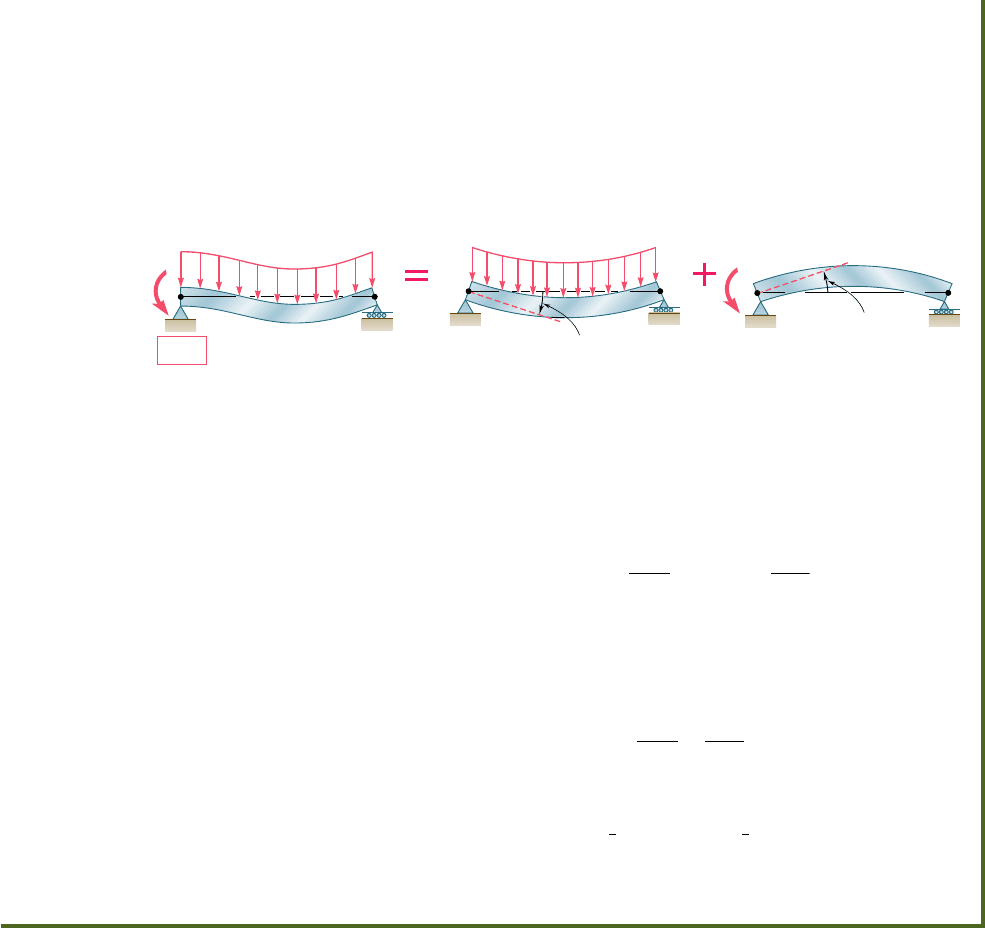
Alternative Solution. We may consider the couple exerted at the
fixed end A as redundant and replace the fixed end by a pin-and-bracket
support. The couple M
A
is now considered as an unknown load (Fig. 9.36a)
and will be determined from the condition that the slope of the beam at
A must be zero. The solution is carried out by considering separately the
slope (u
A
)
w
caused at A by the uniformly distributed load w (Fig. 9.36b)
and the slope (u
A
)
M
produced at the same point by the unknown couple
M
A
(Fig 9.36c).
B
A
w
M
A
M
A
w
B
A
(a)
(b)
(c)
A
0
(
A
)
w
(
A
)
M
B
A
Fig. 9.36
Using the table of Appendix D (cases 6 and 7), and noting that in
case 7, A and B must be interchanged, we find that
1u
A
2
w
52
wL
3
24E
I
1u
A
2
M
5
M
A
L
3
E
I
Writing that the slope at A is the sum of these two quantities and that it
must be zero, we have
u
A
5
1
u
A
2
w
1
1
u
A
2
M
5 0
u
A
52
wL
3
2
5
E
I
1
M
A
L
3
E
I
5 0
and, solving for M
A
,
M
A
5
1
8
wL
2
M
A
5
1
8
wL
2
l
The values of R
A
and R
B
may then be found from the equilibrium equa-
tions (9.52) and (9.53).
584
bee80288_ch09_548-629.indd Page 584 10/30/10 11:22:02 PM user-f499bee80288_ch09_548-629.indd Page 584 10/30/10 11:22:02 PM user-f499 /Users/user-f499/Desktop/Temp Work/Don't Delete Job/MHDQ251:Beer:201/ch09/Users/user-f499/Desktop/Temp Work/Don't Delete Job/MHDQ251:Beer:201/ch09
Apago PDF Enhancer
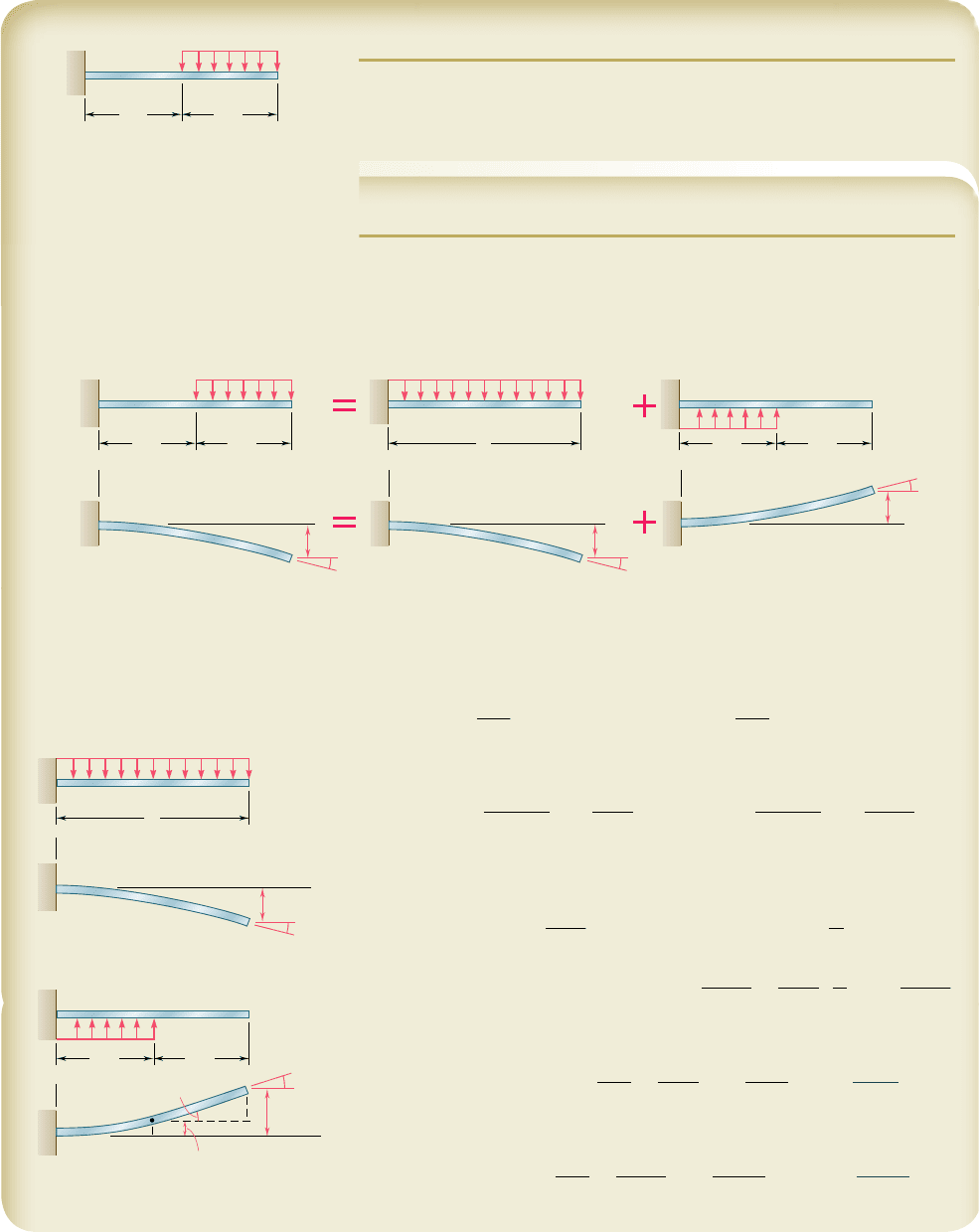
SAMPLE PROBLEM 9.7
For the beam and loading shown, determine the slope and deflection at
point B.
SOLUTION
Principle of Superposition. The given loading can be obtained by
superposing the loadings shown in the following “picture equation.” The
beam AB is, of course, the same in each part of the figure.
B
C
w
A
L/2 L/2
B
C
w
A
y
L/2 L/2
B
x
y
B
A
B
w
Loading I
Loading II
A
L
B
C
w
A
L/2 L/2
B
y
B
A
B
x
x
(y
B
)
I
(
B
)
I
A
y
(
B
)
II
(y
B
)
II
w
B
w
Loading I
Loading II
A
L
y
B
x
(y
B
)
I
(
B
)
I
A
BC
w
A
L/2 L/2
AC
B
x
y
(
B
)
II
(
C
)
II
(y
B
)
II
(y
C
)
II
For each of the loadings I and II, we now determine the slope and deflection
at B by using the table of Beam Deflections and Slopes in Appendix D.
Loading I
1u
B
2
I
52
wL
3
6EI
1y
B
2
I
52
wL
4
8EI
Loading II
1u
C
2
II
51
w1L
y
22
3
6EI
51
wL
3
48EI
1y
C
2
II
51
w1L
y
22
4
8EI
51
wL
4
128EI
In portion CB, the bending moment for loading II is zero and thus the
elastic curve is a straight line.
1u
B
2
II
5 1u
C
2
II
51
wL
3
48EI
1y
B
2
II
5 1y
C
2
II
1 1u
C
2
II
a
L
2
b
5
wL
4
1
2
8EI
1
wL
3
48EI
a
L
2
b
51
7wL
4
384EI
Slope at Point B
u
B
5 1u
B
2
I
1 1u
B
2
II
52
wL
3
6EI
1
wL
3
48EI
52
7wL
3
48EI
u
B
5
7wL
3
48EI
cb
Deflection at B
y
B
5 1y
B
2
I
1 1y
B
2
II
52
wL
4
8EI
1
7wL
4
384EI
52
41wL
4
384EI
y
B
5
41wL
4
384EI
w>
585
bee80288_ch09_548-629.indd Page 585 11/18/10 8:57:12 PM user-f499bee80288_ch09_548-629.indd Page 585 11/18/10 8:57:12 PM user-f499 /Users/user-f499/Desktop/Temp Work/Don't Delete Job/MHDQ251:Beer:201/ch09/Users/user-f499/Desktop/Temp Work/Don't Delete Job/MHDQ251:Beer:201/ch09
Apago PDF Enhancer
586
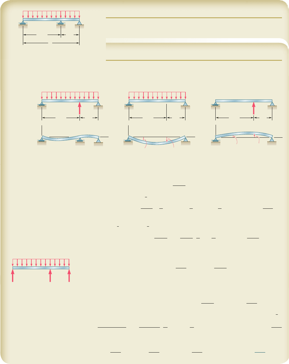
SAMPLE PROBLEM 9.8
For the uniform beam and loading shown, determine (a) the reaction at
each support, (b) the slope at end A.
SOLUTION
Principle of Superposition. The reaction R
B
is designated as redundant
and considered as an unknown load. The deflections due to the distributed
load and to the reaction R
B
are considered separately as shown below.
B
B
w
A
A
y
C
x
C
2L/3 L/3
R
B
R
B
B
w
AC
2L/3 L/3
BAC
2L/3 L/3
[y
B
0]
B
A
y
x
C
(y
B
)
w
(
A
)
w
B
A
y
x
C
(y
B
)
R
(
A
)
R
=
+
+
=
B
w
AC
R
A
0.271 wL R
B
0.688 wL
R
C
0.0413 wL
For each loading the deflection at point B is found by using the table of
Beam Deflections and Slopes in Appendix D.
Distributed Loading. We use case 6, Appendix D
y
52
w
2
4EI
1x
4
2 2L x
3
1 L
3
x2
At point B, x 5
2
3
L:
1y
B
2
w
52
w
24EI
ca
2
3
Lb
4
2 2L a
2
3
Lb
3
1 L
3
a
2
3
Lbd520.01132
wL
4
EI
Redundant Reaction Loading. From case 5, Appendix D, with
a
5
2
3
L and b 5
1
3
L, we have
1y
B
2
R
52
Pa
2
b
2
3EIL
51
R
B
3EIL
a
2
3
L
b
2
a
L
3
b
2
5 0.01646
R
B
L
3
EI
a. Reactions at Supports. Recalling that y
B
5 0, we write
y
B
5 1y
B
2
w
1 1y
B
2
R
0 520.01132
wL
4
EI
1 0.01646
R
B
L
3
EI
R
B
5 0.688wL
x
b
Since the reaction R
B
is now known, we may use the methods of statics to
determine the other reactions: R
A
5 0.271wL
x
R
C
5 0.0413wL
x
>
b. Slope at End A. Referring again to Appendix D, we have
Distributed Loading.
1u
A
2
w
52
wL
3
2
4EI
520.04167
wL
3
EI
Redundant Reaction Loading. For P 52R
B
520.688wL and b 5
1
3
L
1u
A
2
R
52
Pb1L
2
2 b
2
2
6EIL
51
0.688w
L
6EIL
a
L
3
bcL
2
2 a
L
3
b
2
d
1u
A
2
R
5 0.03398
wL
3
EI
Finally, u
A
5
1
u
A
2
w
1
1
u
A
2
R
u
A
520.04167
wL
3
EI
1 0.03398
wL
3
EI
520.00769
wL
3
EI
u
A
5 0.00769
wL
3
EI
cb
B
w
A
C
2L/3
L
L/3
bee80288_ch09_548-629.indd Page 586 10/30/10 11:22:13 PM user-f499bee80288_ch09_548-629.indd Page 586 10/30/10 11:22:13 PM user-f499 /Users/user-f499/Desktop/Temp Work/Don't Delete Job/MHDQ251:Beer:201/ch09/Users/user-f499/Desktop/Temp Work/Don't Delete Job/MHDQ251:Beer:201/ch09
