Beer F.P., Johnston E.R., DeWolf J.T., Mazurek D.F. Mechanics of Materials
Подождите немного. Документ загружается.

Apago PDF Enhancer
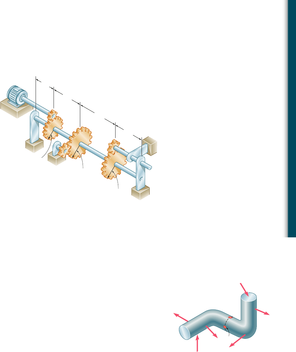
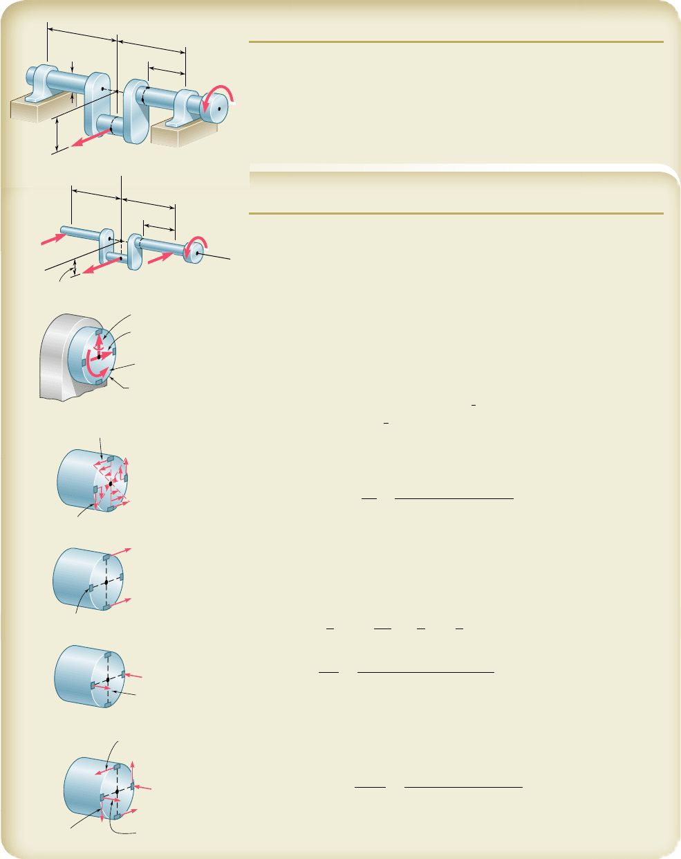
8.29 The solid shaft AE rotates at 600 rpm and transmits 60 hp from
the motor M to machine tools connected to gears G and H. Know-
ing that t
all
5 8 ksi and that 40 hp is taken off at gear G and 20 hp
is taken off at gear H, determine the smallest permissible diameter
of shaft AE.
*8.4 STRESSES UNDER COMBINED LOADINGS
In Chaps. 1 and 2 you learned to determine the stresses caused by
a centric axial load. In Chap. 3, you analyzed the distribution of
stresses in a cylindrical member subjected to a twisting couple. In
Chap. 4, you determined the stresses caused by bending couples and,
in Chaps. 5 and 6, the stresses produced by transverse loads. As you
will see presently, you can combine the knowledge you have acquired
to determine the stresses in slender structural members or machine
components under fairly general loading conditions.
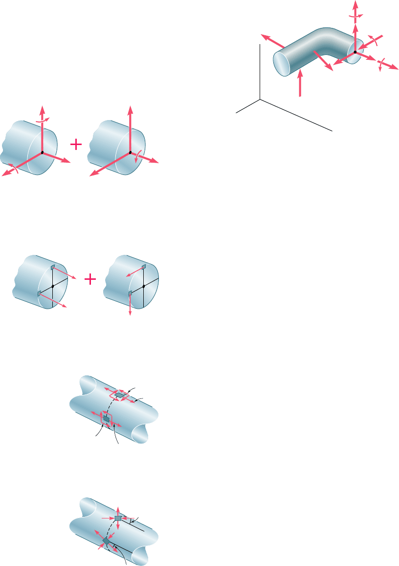
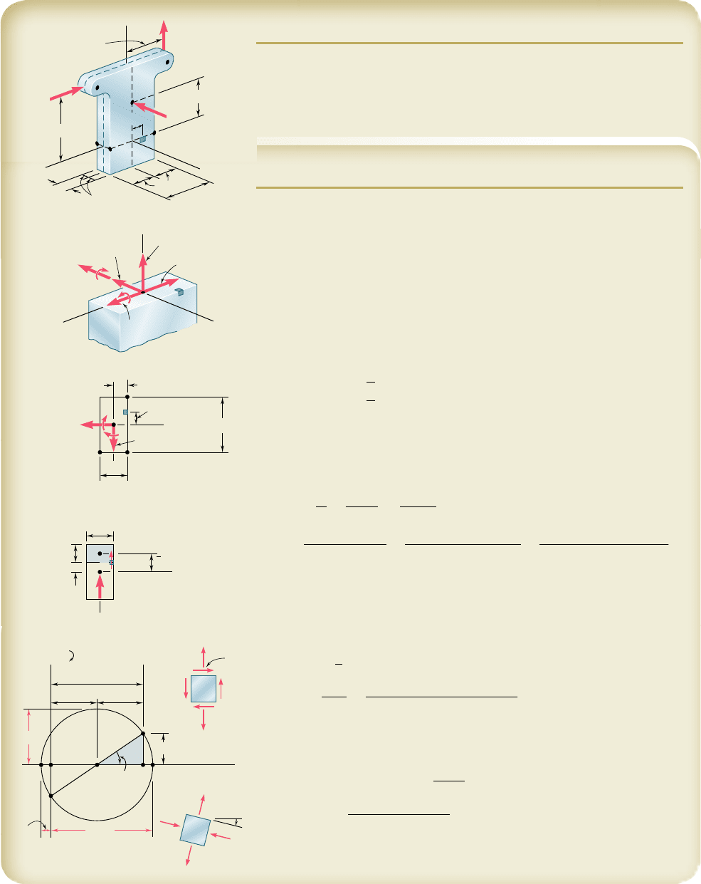
Consider, for example, the bent member ABDE of circular
cross section that is subjected to several forces (Fig. 8.15). In order
to determine the stresses produced at points H or K by the given
loads, we first pass a section through these points and determine the
force-couple system at the centroid C of the section that is required
to maintain the equilibrium of portion ABC.† This system represents
the internal forces in the section and, in general, consists of three
M
A
3 in.
C
F
B
4 in.
6 in.
6 in.
8 in.
C
D
H
G
4 in.
4 in.
E
Fig. P8.29
†The force-couple system at C can also be defined as equivalent to the forces acting on
the portion of the member located to the right of the section (see Example 8.01).
8.4 Stresses under Combined Loadings
8.30 Solve Prob. 8.29, assuming that 30 hp is taken off at gear G and
30 hp is taken off at gear H.
F
3
F
4
F
6
F
5
F
2
F
1
B
D
E
K
H
A
Fig. 8.15 Member ABDE subjected to
several forces.
527
bee80288_ch08_512-547.indd Page 527 10/30/10 4:58:47 PM user-f499bee80288_ch08_512-547.indd Page 527 10/30/10 4:58:47 PM user-f499/Users/user-f499/Desktop/Temp Work/Don't Delete Job/MHDQ251:Beer:201/ch08/Users/user-f499/Desktop/Temp Work/Don't Delete Job/MHDQ251:Beer:201/ch
Apago PDF Enhancer
528
Principal Stresses under a Given Loading
force components and three couple vectors that will be assumed
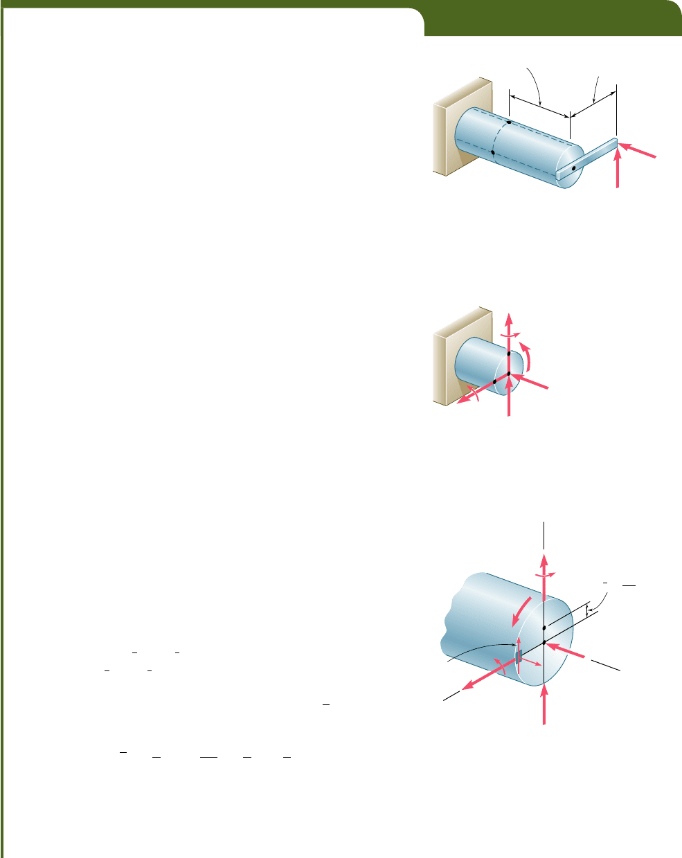
directed as shown (Fig. 8.16).
The force P is a centric axial force that produces normal stresses
in the section. The couple vectors M
y
and M
z
cause the member to
bend and also produce normal stresses in the section. They have
therefore been grouped with the force P in part a of Fig. 8.17 and
the sums s
x
of the normal stresses they produce at points H and K
have been shown in part a of Fig. 8.18. These stresses can be deter-
mined as shown in Sec. 4.14.
On the other hand, the twisting couple T and the shearing
forces V
y
and V
z
produce shearing stresses in the section. The sums
t
xy
and t
xz
of the components of the shearing stresses they produce
at points H and K have been shown in part b of Fig. 8.18 and can
be determined as indicated in Secs. 3.4 and 6.3.† The normal and
shearing stresses shown in parts a and b of Fig. 8.18 can now be
combined and displayed at points H and K on the surface of the
member (Fig. 8.19).
The principal stresses and the orientation of the principal
planes at points H and K can be determined from the values of s
x
,
t
xy
, and t
xz
at each of these points by one of the methods presented
in Chap. 7 (Fig. 8.20). The values of the maximum shearing stress
at each of these points and the corresponding planes can be found
in a similar way.
The results obtained in this section are valid only to the extent
that the conditions of applicability of the superposition principle
(Sec. 2.12) and of Saint-Venant’s principle (Sec. 2.17) are met. This
means that the stresses involved must not exceed the proportional
limit of the material, that the deformations due to one of the loadings
must not affect the determination of the stresses due to the others,
and that the section used in your analysis must not be too close to
the points of application of the given forces. It is clear from the first
of these requirements that the method presented here cannot be
applied to plastic deformations.
†Note that your present knowledge allows you to determine the effect of the twisting
couple T only in the cases of circular shafts, of members with a rectangular cross section
(Sec. 3.12), or of thin-walled hollow members (Sec. 3.13).
M
y
T
P
M
z
V
z
F
3
F
2
F
1
V
y
B
y
x
z
C
A
Fig. 8.16 Determination of internal forces
at the section for stress analysis.
M
y
V
y
V
z
P
M
z
C
T
(a)(b)
C
Fig. 8.17 Internal forces separated into
(a) those causing normal stresses (b) those
causing shearing stresses.
C
H
K
(a)(b)
C
K
x
xy
x
C
H
CK
xz
Fig. 8.18 Normal stresses and
shearing stresses.
K
H
xz
xy
x
x
Fig. 8.19 Combined
stresses.
K
H
p
p
Fig. 8.20 Principal
stresses and orientation
of principal planes.
bee80288_ch08_512-547.indd Page 528 10/30/10 4:58:52 PM user-f499bee80288_ch08_512-547.indd Page 528 10/30/10 4:58:52 PM user-f499/Users/user-f499/Desktop/Temp Work/Don't Delete Job/MHDQ251:Beer:201/ch08/Users/user-f499/Desktop/Temp Work/Don't Delete Job/MHDQ251:Beer:201/ch
Apago PDF Enhancer
529
EXAMPLE 8.01
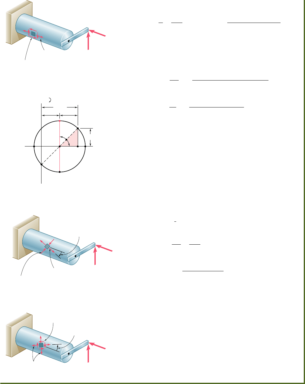
Two forces P
1
and P
2
, of magnitude P
1
5 15 kN and P
2
5 18 kN, are applied
as shown to the end A of bar AB, which is welded to a cylindrical member
BD of radius c 5 20 mm (Fig. 8.21). Knowing that the distance from A to
the axis of member BD is a 5 50 mm and assuming that all stresses remain
below the proportional limit of the material, determine (a) the normal and
shearing stresses at point K of the transverse section of member BD located
at a distance b 5 60 mm from end B, (b) the principal axes and principal
stresses at K, (c) the maximum shearing stress at K.
Internal Forces in Given Section. We first replace the forces P
1
and
P
2
by an equivalent system of forces and couples applied at the center C of
the section containing point K (Fig. 8.22). This system, which represents the
internal forces in the section, consists of the following forces and couples:
1. A centric axial force F equal to the force P
1
, of magnitude
F 5 P
1
5 15
k
N
2. A shearing force V equal to the force P
2
, of magnitude
V 5 P
2
5 18
k
N
3. A twisting couple T of torque T equal to the moment of P
2
about
the axis of member BD:
T 5 P
2
a 5
1
18 kN
21
50 mm
2
5 900 N ? m
4. A bending couple M
y
, of moment M
y
equal to the moment of P
1
about a vertical axis through C:
M
y
5 P
1
a 5
1
15 kN
21
50 mm
2
5 750 N ? m
5. A bending couple M
z
, of moment M
z
equal to the moment of P
2
about a transverse, horizontal axis through C:
M
z
5 P
2
b 5
1
18 kN
21
60 mm
2
5 1080 N ? m
The results obtained are shown in Fig. 8.23.
a. Normal and Shearing Stresses at Point K. Each of the
forces and couples shown in Fig. 8.23 can produce a normal or shearing
stress at point K. Our purpose is to compute separately each of these
stresses, and then to add the normal stresses and add the shearing stresses.
But we must first determine the geometric properties of the section.
Geometric Properties of the Section We have
A 5 pc
2
5 p
1
0.020 m
2
2
5 1.257 3 10
23
m
2
I
y
5 I
z
5
1
4
pc
4
5
1
4
p10.020 m2
4
5 125.7 3 10
29
m
4
J
C
5
1
2
pc
4
5
1
2
p10.020 m2
4
5 251.3 3 10
29
m
4
We also determine the first moment Q and the width t of the area of the
cross section located above the z axis. Recalling that
y 5 4c
y
3p for a
semicircle of radius c, we have
Q 5 A¿
y 5
a
1
2
pc
2
b
a
4c
3p
b
5
2
3
c
3
5
2
3
10.020 m2
3
5 5
.
33 3 10
2
6
m
3
and
t 5 2c 5 2
1
0.020 m
2
5 0.040 m
Normal Stresses. We observe that normal stresses are produced at
K by the centric force F and the bending couple M
y
, but that the couple M
z
H
D
K
B
A
P
1
⫽ 15 kN
P
2
⫽ 18 kN
b ⫽ 60 mm
a ⫽ 50 mm
Fig. 8.21
K
D
H
C
M
z
M
y
V
F
T
Fig. 8.22
T ⫽ 900 N · m
y
3
4c
x
C
K
z
V ⫽ 18 kN
F ⫽ 15 kN
y ⫽
M
z
x
xy
M
y
⫽ 750 N · m
Fig. 8.23
bee80288_ch08_512-547.indd Page 529 11/18/10 7:43:30 PM user-f499bee80288_ch08_512-547.indd Page 529 11/18/10 7:43:30 PM user-f499 /Users/user-f499/Desktop/Temp Work/Don't Delete Job/MHDQ251:Beer:201/ch08/Users/user-f499/Desktop/Temp Work/Don't Delete Job/MHDQ251:Beer:201/ch08
Apago PDF Enhancer
does not produce any stress at K, since K is located on the neutral axis cor-
responding to that couple. Determining each sign from Fig. 8.23, we write
s
x
52
F
A
1
M
y
c
I
y
5211.9 MPa 1
1750 N ? m210.020 m
2
125.7 3 10
29
m
4
52
11.9
MP
a
1
119.3
MP
a
s
x
5110
7
.4 MPa
Shearing Stresses. These consist of the shearing stress (t
xy
)
V
due
to the vertical shear V and of the shearing stress (t
xy
)
twist
caused by the
torque T. Recalling the values obtained for Q, t, I
z
, and J
C
, we write
1t
xy
2
V
51
V
Q
I
z
t
51
118 3 10
3
N21 5.33 3 10
2
6
m
3
2
1
125.7 3 10
29
m
4
21
0.040 m
2
51
19.1
MP
a
1t
xy
2
twist
52
Tc
J
C
52
1
900 N ? m
2
1
0.020 m
2
251.3 3 10
29
m
4
5271.6 MPa
Adding these two expressions, we obtain t
xy
at point K.
t
xy
5
1
t
xy
2
V
1
1
t
xy
2
twist
5119.1 MPa 2 71.6 MPa
t
xy
5252.5 MPa
In Fig. 8.24, the normal stress s
x
and the shearing stresses and t
xy
have
been shown acting on a square element located at K on the surface of
the cylindrical member. Note that shearing stresses acting on the longi-
tudinal sides of the element have been included.
b. Principal Planes and Principal Stresses at Point K. We can
use either of the two methods of Chap. 7 to determine the principal
planes and principal stresses at K. Selecting Mohr’s circle, we plot point
X of coordinates s
x
5 1107.4 MPa and 2t
xy
5 152.5 MPa and point Y
of coordinates s
y
5 0 and 1t
xy
5 252.5 MPa and draw the circle of
diameter XY (Fig. 8.25). Observing that
OC 5 CD 5
1
2
1
107.4
2
5 53.7 MPa D
X
5 52
.
5 MP
a
we determine the orientation of the principal planes:
tan 2u
p
5
DX
C
D
5
52.5
53
.
7
5 0.97765
2
u
p
5
44
.
4°
i
u
p
5
22
.
2°
i
We now determine the radius of the circle,
R 5 2
1
53.7
2
2
1
1
52.5
2
2
5 75.1 MPa
and the principal stresses,
s
m
a
x
5 OC 1 R 5 53.7 1 75.1 5 128.8 MPa
s
min
5 OC 2 R 5 53.7 2 75.1 5221.4 MPa
The results obtained are shown in Fig. 8.26.
c. Maximum Shearing Stress at Point K. This stress corre-
sponds to points E and F in Fig. 8.25. We have
t
m
a
x
5 CE 5 R 5 75.1 MPa
Observing that 2u
s
5 908 2 2u
p
5 908 2 44.48 5 45.68, we conclude that
the planes of maximum shearing stress form an angle u
p
5
22
.
8°
l with
the horizontal. The corresponding element is shown in Fig. 8.27. Note
that the normal stresses acting on this element are represented by OC in
Fig. 8.25 and are thus equal to 153.7 MPa.
530
D
A
x
107.4 MPa
xy
52.5 MPa
15 kN
18 kN
Fig. 8.24
A
F
X
Y
OB
D
E
(MPa)
2
52.5
53.7 53.7
107.4
s
2
p
(MPa)
C
Fig. 8.25
max
128.8 MPa
min
21.4 MPa
D
A
15 kN
18 kN
p
22.2
B
Fig. 8.26
D
A
15 kN
18 kN
s
22.8
53.7 MPa
B
max
75.1 MPa
Fig. 8.27
bee80288_ch08_512-547.indd Page 530 11/17/10 11:55:56 PM user-f499bee80288_ch08_512-547.indd Page 530 11/17/10 11:55:56 PM user-f499 /Users/user-f499/Desktop/Temp Work/Don't Delete Job/MHDQ251:Beer:201/ch08/Users/user-f499/Desktop/Temp Work/Don't Delete Job/MHDQ251:Beer:201/ch08
Apago PDF Enhancer
531
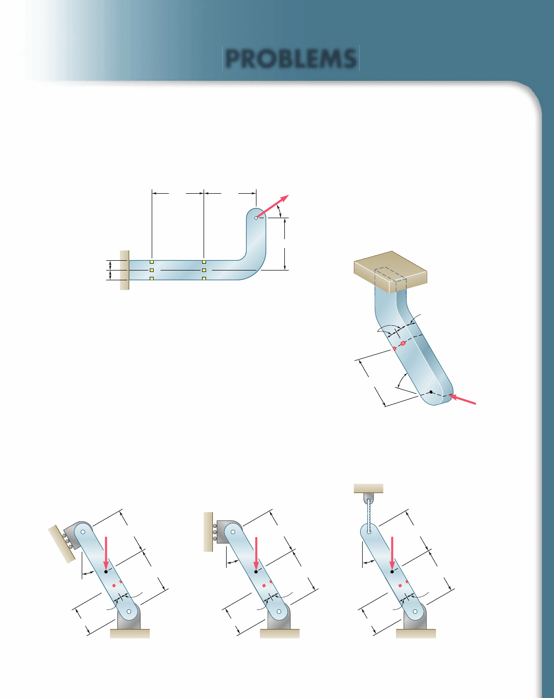
SAMPLE PROBLEM 8.4
A horizontal 500-lb force acts at point D of crankshaft AB which is held in
static equilibrium by a twisting couple T and by reactions at A and B. Know-
ing that the bearings are self-aligning and exert no couples on the shaft,
determine the normal and shearing stresses at points H, J, K, and L located
at the ends of the vertical and horizontal diameters of a transverse section
located 2.5 in. to the left of bearing B.
SOLUTION
Free Body. Entire Crankshaft. A 5 B 5 250 lb
1l
©
M
x
5 0: 2
1
500 lb
21
1.8 in.
2
1 T 5 0 T 5 900
lb
? in.
Internal Forces in Transverse Section. We replace the reaction B and
the twisting couple T by an equivalent force-couple system at the center C
of the transverse section containing H, J, K, and L.
V 5 B 5 250
lb
T 5 900
lb
? in.
M
y
5
1
250 lb
21
2.5 in.
2
5 625 lb ? in.
The geometric properties of the 0.9-in.-diameter section are
A
5 p
1
0.45 in.
2
2
5 0.636 in
2
I 5
1
4
p
1
0.45 in.
2
4
5 32.2 3 10
23
in
4
J
5
1
2
p10.45 in.2
4
5 64.4 3 10
23
in
4
Stresses Produced by Twisting Couple T. Using Eq. (3.8), we determine
the shearing stresses at points H, J, K, and L and show them in Fig. (a).
t 5
T
c
J
5
1
900 lb ? in.
21
0.45 in.
2
64.4 3 10
23
in
4
5 6290 psi
Stresses Produced by Shearing Force V. The shearing force V pro-
duces no shearing stresses at points J and L. At points H and K we first
compute Q for a semicircle about a vertical diameter and then determine
the shearing stress produced by the shear force V 5 250 lb. These stresses
are shown in Fig. (b).
Q 5
a
1
2
pc
2
b
a
4c
3p
b
5
2
3
c
3
5
2
3
10.45 in.2
3
5 60.7 3 10
23
in
3
t 5
V
Q
It
5
1250 lb2160.7 3 10
2
3
in
3
2
1
32.2 3 10
23
in
4
21
0.9 in.
2
5 524 psi
Stresses Produced by the Bending Couple M
y
. Since the bending
couple M
y
acts in a horizontal plane, it produces no stresses at H and K.
Using Eq. (4.15), we determine the normal stresses at points J and L and
show them in Fig. (c).
s 5
0
M
y
0
c
I
5
1625 lb ? in.210.45 in.
2
32
.
2 3 10
23
in
4
5 8730 psi
Summary. We add the stresses shown and obtain the total normal and
shearing stresses at points H, J, K, and L.
4.5 in.
0.90 in.
A
E
D
K
G
H
J
B
T
4.5 in.
2.5 in.
1.8 in.
500 lb
A
D
B
z
y
x
4.5 in.
4.5 in.
2.5 in.
1.8 in.
500 lb
A
250 lb
B 250 lb
T
E
J
C
G
K
H
L
M
y
625 lb · in.
T 900 lb · in.
0.9-in. diameter
V 250 lb
J
K
H
L
6290 psi
6290 psi
6290 psi
6290 psi
(a)
J
K
H
L
524 psi
524 psi
0
(b)
0
0
J
K
H
L
8730 psi
8730 psi
(c)
J
K
H
L
5770 psi
6290 psi
6290 psi
6810 psi
8730 psi
8730 psi
bee80288_ch08_512-547.indd Page 531 11/17/10 11:56:07 PM user-f499bee80288_ch08_512-547.indd Page 531 11/17/10 11:56:07 PM user-f499 /Users/user-f499/Desktop/Temp Work/Don't Delete Job/MHDQ251:Beer:201/ch08/Users/user-f499/Desktop/Temp Work/Don't Delete Job/MHDQ251:Beer:201/ch08
Apago PDF Enhancer
SAMPLE PROBLEM 8.5
Three forces are applied as shown at points A, B, and D of a short steel post.
Knowing that the horizontal cross section of the post is a 40 3 140-mm
rectangle, determine the principal stresses, principal planes and maximum
shearing stress at point H.
SOLUTION
Internal Forces in Section EFG. We replace the three applied forces
by an equivalent force-couple system at the center C of the rectangular
section EFG. We have
V
x
5230
k
NP 5 50
k
NV
z
5275
k
N
M
x
5
1
50 kN
21
0.130 m
2
2
1
75 kN
21
0.200 m
2
528.5 kN ? m
M
y
5
0
M
z
5
1
30 kN
21
0.100 m
2
5 3 kN ? m
We note that there is no twisting couple about the y axis. The geo-
metric properties of the rectangular section are
A
5
1
0.040 m
21
0.140 m
2
5 5.6 3 10
23
m
2
I
x
5
1
12
1
0.040 m
21
0.140 m
2
3
5 9.15 3 10
26
m
4
I
z
5
1
12
1
0.140 m
21
0.040 m
2
3
5 0.747 3 10
26
m
4
Normal Stress at H. We note that normal stresses s
y
are produced
by the centric force P and by the bending couples M
x
and M
z
. We deter-
mine the sign of each stress by carefully examining the sketch of the force-
couple system at C.
s
y
51
P
A
1
0
M
z
0
a
I
z
2
0
M
x
0
b
I
x
5
50 kN
5
.
6 3 10
23
m
2
1
1
3 kN ? m
21
0.020 m
2
0.747 3 10
26
m
4
2
1
8.5 kN ? m
21
0.025 m
2
9.15 3 10
26
m
4
s
y
5
8
.
93
MPa 1
80
.
3
MPa 2
23
.
2
MPa s
y
5
66
.
0
MPa
◀
Shearing Stress at H. Considering first the shearing force V
x
, we note
that Q 5 0 with respect to the z axis, since H is on the edge of the cross
section. Thus V
x
produces no shearing stress at H. The shearing force V
z
does produce a shearing stress at H and we write
Q 5 A
1
y
1
5 310.040 m210.045 m2410.0475 m25 85.5 3 10
2
6
m
3
t
yz
5
V
z
Q
I
x
t
5
175 kN2185.5 3 10
2
6
m
3
2
1
9.15 3 10
26
m
4
21
0.040 m
2
t
yz
5 17.52 MPa
◀
Principal Stresses, Principal Planes, and Maximum Shearing Stress
at H. We draw Mohr’s circle for the stresses at point H
tan 2u
p
5
17.52
33
.
0
2u
p
5 2
7
.96° u
p
5
13
.
98°
◀
R 5 2
1
33.0
2
2
1
1
17.52
2
2
5 37.4 MPa t
m
a
x
5 3
7
.4 MPa
◀
s
m
a
x
5 OA 5 OC 1 R 5 33.0 1 3
7
.4 s
m
a
x
5
7
0.4 MPa
◀
s
min
5 OB 5 OC 2 R 5 33.0 2 3
7
.4 s
min
52
7
.4 MPa
◀
532
70 mm
100 mm
25 mm
200 mm
130 mm
75 kN
50 kN
30 kN
20 mm
40 mm
z
x
E
A
B
y
G
D
F
H
140 mm
E
C
F
H
G
z
y
M
x
8.5 kN · m
V
x
30 kN
P 50 kN
V
z
75 kN
M
z
3 kN · m
x
E
C
G
H
b 0.025 m
0.040 m
a 0.020 m
0.140 m
F
z
M
z
8.5 kN · m
M
z
3 kN · m
H
C
A
1
V
z
yz
t 0.040 m
0.045 m
0.025 m
y
1
0.0475 m
z
CO
B
33.0 33.0
13.98
A
D
R
Y
Z
2
p
max
y
66.0 MPa
y
yz
17.52 MPa
(MPa)
(MPa)
max
max
min
min
yz
bee80288_ch08_512-547.indd Page 532 11/17/10 11:56:25 PM user-f499bee80288_ch08_512-547.indd Page 532 11/17/10 11:56:25 PM user-f499 /Users/user-f499/Desktop/Temp Work/Don't Delete Job/MHDQ251:Beer:201/ch08/Users/user-f499/Desktop/Temp Work/Don't Delete Job/MHDQ251:Beer:201/ch08
Apago PDF Enhancer
PROBLEMS
533
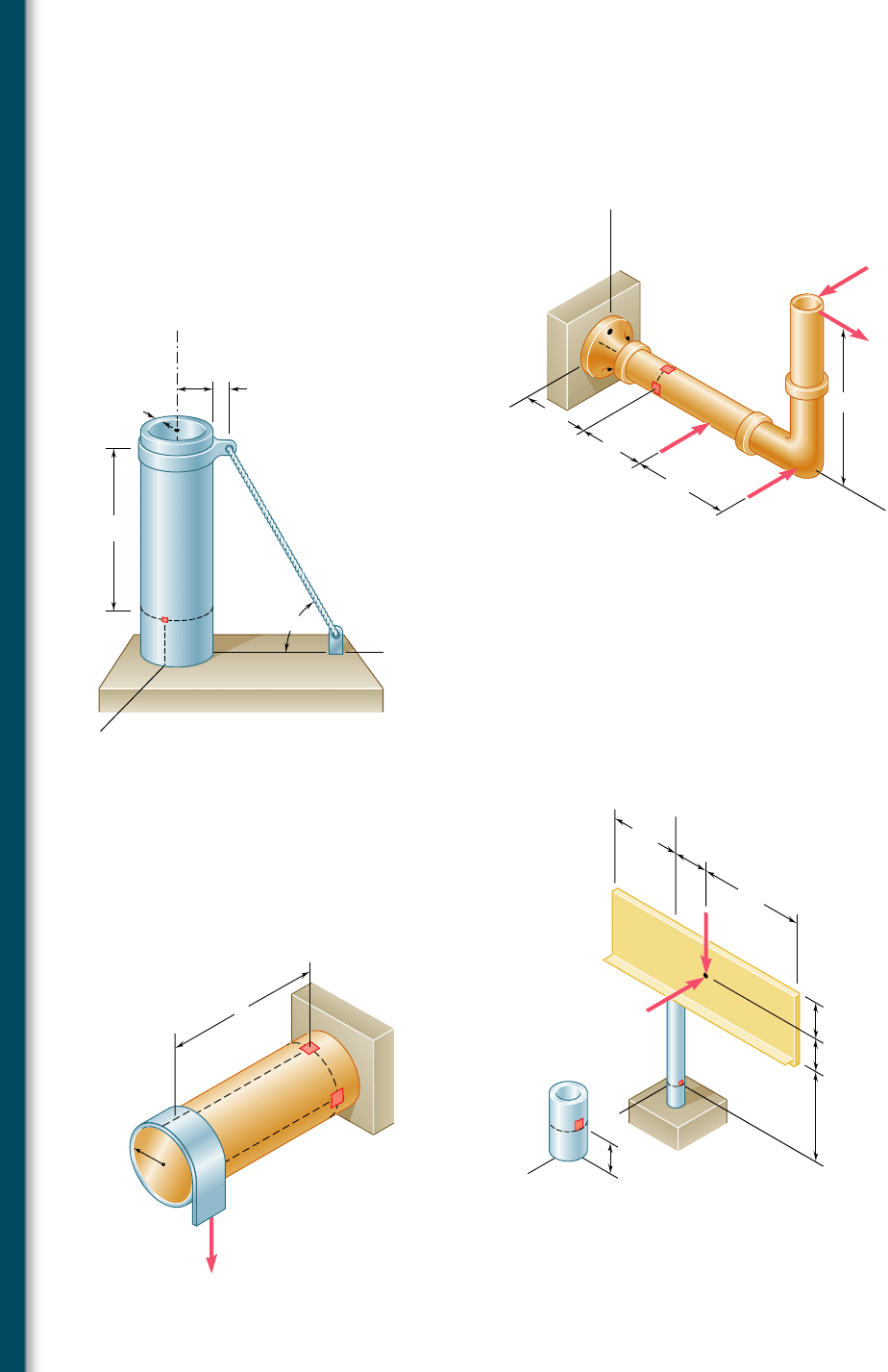
8.31 A 6-kip force is applied to the machine element AB as shown.
Knowing that the uniform thickness of the element is 0.8 in., deter-
mine the normal and shearing stresses at (a) point a, (b) point b,
(c) point c.
8.32 A 6-kip force is applied to the machine element AB as shown.
Knowing that the uniform thickness of the element is 0.8 in., deter-
mine the normal and shearing stresses at (a) point d, (b) point e,
(c) point f.
8.33 For the bracket and loading shown, determine the normal and
shearing stresses at (a) point a, (b) point b.
8.34 through 8.36 Member AB has a uniform rectangular cross
section of 10 3 24 mm. For the loading shown, determine the
normal and shearing stresses at (a) point H, (b) point K.
6 kips
8 in. 8 in.
35⬚
8 in.
1.5 in.
1.5 in.
Ba
b
c
d
A
e
f
Fig. P8.31 and P8.32
20 mm
100 mm
18 mm
4 kN
a
b
60
Fig. P8.33
30
60 mm
60 mm
K
H
G
B
A
12 mm
12 mm
40 mm
9 kN
Fig. P8.34
30
60 mm
60 mm
K
H
G
B
A
12 mm
12 mm
40 mm
9 kN
Fig. P8.35
30
60 mm
60 mm
K
H
G
B
A
12 mm
12 mm
40 mm
9 kN
Fig. P8.36
bee80288_ch08_512-547.indd Page 533 10/30/10 4:59:56 PM user-f499bee80288_ch08_512-547.indd Page 533 10/30/10 4:59:56 PM user-f499/Users/user-f499/Desktop/Temp Work/Don't Delete Job/MHDQ251:Beer:201/ch08/Users/user-f499/Desktop/Temp Work/Don't Delete Job/MHDQ251:Beer:201/ch
Apago PDF Enhancer
534
Principal Stresses under a Given Loading
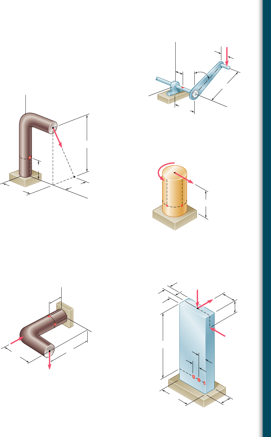
8.37 Several forces are applied to the pipe assembly shown. Knowing
that the pipe has inner and outer diameters equal to 1.61 and
1.90 in., respectively, determine the normal and shearing stresses
at (a) point H, (b) point K.
4 in.
6 in.
4 in.
H
y
z
K
150 lb
50 lb
x
10 in.
150 lb
200 lb
D
Fig. P8.37
8.38 The steel pile AB has a 100-mm outer diameter and an 8-mm wall
thickness. Knowing that the tension in the cable is 40 kN, deter-
mine the normal and shearing stresses at point H.
8.39 The billboard shown weighs 8000 lb and is supported by a struc-
tural tube that has a 15-in. outer diameter and a 0.5-in. wall thick-
ness. At a time when the resultant of the wind pressure is 3 kips,
located at the center C of the billboard, determine the normal and
shearing stresses at point H.
50 mm
225 mm
20 mm
A
H
E
D
B
z
x
y
t 8 mm
60
Fig. P8.38
2 ft
8 ft
H
x
x
z
H
z
3 ft
6 ft
3 ft
9 ft
3 ft
3 kips
8 kips
C
y
Fig. P8.39
F
c
K
H
l
Fig. P8.40
8.40 A thin strap is wrapped around a solid rod of radius c 5 20 mm
as shown. Knowing that l 5 100 mm and F 5 5 kN, determine the
normal and shearing stresses at (a) point H, (b) point K.
bee80288_ch08_512-547.indd Page 534 10/30/10 5:00:12 PM user-f499bee80288_ch08_512-547.indd Page 534 10/30/10 5:00:12 PM user-f499/Users/user-f499/Desktop/Temp Work/Don't Delete Job/MHDQ251:Beer:201/ch08/Users/user-f499/Desktop/Temp Work/Don't Delete Job/MHDQ251:Beer:201/ch
Apago PDF Enhancer
535
Problems
8.41 A vertical force P of magnitude 60 lb is applied to the crank at point
A. Knowing that the shaft BDE has a diameter of 0.75 in., determine
the principal stresses and the maximum shearing stress at point H
located at the top of the shaft, 2 in. to the right of support D.
8.42 A 13-kN force is applied as shown to the 60-mm-diameter cast-iron
post ABD. At point H, determine (a) the principal stresses and
principal planes, (b) the maximum shearing stress.
8.43 A 10-kN force and a 1.4-kN ? m couple are applied at the top of
the 65-mm diameter brass post shown. Determine the principal
stresses and maximum shearing stress at (a) point H, (b) point K.
8.44 Forces are applied at points A and B of the solid cast-iron bracket
shown. Knowing that the bracket has a diameter of 0.8 in., deter-
mine the principal stresses and the maximum shearing stress at
(a) point H, (b) point K.
60°
8 in.
2 in.
5 in.
1 in.
z
E
D
H
A
x
B
y
P
Fig. P8.41
H
A
B
D
x
z
E
13 kN
300 mm
125 mm
150 mm
100 mm
y
Fig. P8.42
C
240 mm
1.4 kN · m
10 kN
H
K
Fig. P8.43
H
B
A
z
y
x
K
600 lb
3.5 in.
2.5 in.
1 in.
2500 lb
Fig. P8.44
8.45 Three forces are applied to the bar shown. Determine the normal
and shearing stresses at (a) point a, (b) point b, (c) point c.
8.46 Solve Prob. 8.45, assuming that h 5 12 in.
h 10.5 in.
0.9 in.
4.8 in.
1.8 in.
0.9 in.
2.4 in.
50 kips
2 kips
6 kips
2 in.
1.2 in.
1.2 in.
a
b
c
C
Fig. P8.45
bee80288_ch08_512-547.indd Page 535 11/17/10 11:56:44 PM user-f499bee80288_ch08_512-547.indd Page 535 11/17/10 11:56:44 PM user-f499 /Users/user-f499/Desktop/Temp Work/Don't Delete Job/MHDQ251:Beer:201/ch08/Users/user-f499/Desktop/Temp Work/Don't Delete Job/MHDQ251:Beer:201/ch08
Apago PDF Enhancer
536
Principal Stresses under a Given Loading
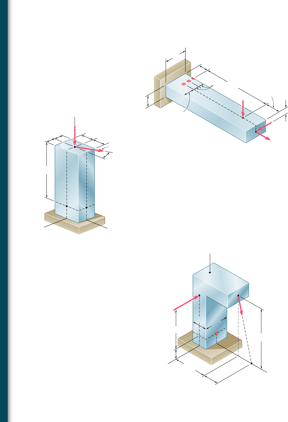
8.47 Three forces are applied to the bar shown. Determine the normal
and shearing stresses at (a) point a, (b) point b, (c) point c.
8.48 Solve Prob. 8.47, assuming that the 750-N force is directed verti-
cally upward.
8.49 For the post and loading shown, determine the principal stresses,
principal planes, and maximum shearing stress at point H.
8.50 For the post and loading shown, determine the principal stresses,
principal planes, and maximum shearing stress at point K.
8.51 Two forces are applied to the small post BD as shown. Knowing
that the vertical portion of the post has a cross section of 1.5 3
2.4 in., determine the principal stresses, principal planes, and maxi-
mum shearing stress at point H.
24 mm
15 mm
32 mm
60 mm
180 mm
a
b
c
C
40 mm
30 mm
500 N
750 N
10 kN
16 mm
Fig. P8.47
50 mm
50 mm
75 mm
75 mm
50 kN
120 kN
y
z
x
30
C
375 mm
H
K
Fig. P8.49 and P8.50
6000 lb
500 lb
4 in.
6 in.
3.25 in.
1.75 in.
2.4 in.
1.5 in.
y
H
B
D
z
x
1 in.
Fig. P8.51
bee80288_ch08_512-547.indd Page 536 10/30/10 5:00:32 PM user-f499bee80288_ch08_512-547.indd Page 536 10/30/10 5:00:32 PM user-f499/Users/user-f499/Desktop/Temp Work/Don't Delete Job/MHDQ251:Beer:201/ch08/Users/user-f499/Desktop/Temp Work/Don't Delete Job/MHDQ251:Beer:201/ch
