Beer F.P., Johnston E.R., DeWolf J.T., Mazurek D.F. Mechanics of Materials
Подождите немного. Документ загружается.

Apago PDF Enhancer
487
components define the parallelogram into which a square with sides
respectively parallel to the x9 and y9 axes is deformed.
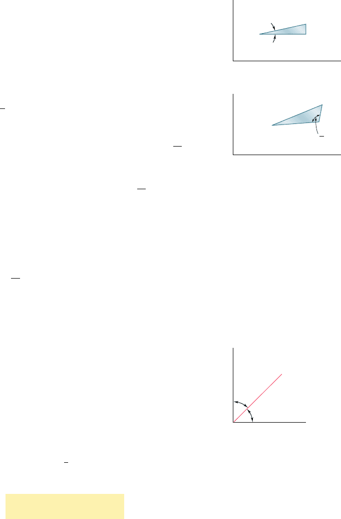
We first derive an expression for the normal strain P(u) along
a line AB forming an arbitrary angle u with the x axis. To do so, we
consider the right triangle ABC, which has AB for hypothenuse (Fig.
7.58a), and the oblique triangle A9B9C9 into which triangle ABC is
deformed (Fig. 7.58b). Denoting by Ds the length of AB, we express
the length of A9B9 as Ds [1 1 P(u)]. Similarly, denoting by Dx and
Dy the lengths of sides AC and CB, we express the lengths of A9C9
and C9B9 as Dx (1 1 P
x
) and Dy (1 1 P
y
), respectively. Recalling
from Fig. 7.56 that the right angle at C in Fig. 7.58a deforms into
an angle equal to
p
2
1 g
x
y
in Fig. 7.58b, and applying the law of
cosines to triangle A9B9C9, we write
1A¿B¿2
2
5 1A¿C¿2
2
1 1C¿B¿2
2
2 21A¿C¿21C¿B¿2 cos
a
p
2
1 g
xy
b
1¢s2
2
31 1 P1u24
2
5 1¢x2
2
11 1 P
x
2
2
1 1¢y2
2
11 1 P
y
2
2
221¢x211 1 P
x
21¢y211 1 P
y
2 cos
a
p
2
1 g
xy
b
(7.38)
But from Fig. 7.58a we have
¢x 5
1
¢s
2
cos u ¢y 5
1
¢s
2
sin u (7.39)
and we note that, since g
xy
is very small,
cos
a
p
2
1 g
xy
b
52sin g
xy
< 2g
xy
(7.40)
Substituting from Eqs. (7.39) and (7.40) into Eq. (7.38), recalling
that cos
2
u 1 sin
2
u 5 1, and neglecting second-order terms in P(u),
P
x
, P
y
, and g
xy
, we write
P1u25 P
x
cos
2
u 1 P
y
sin
2
u 1 g
x
y
sin u cos u (7.41)
Equation (7.41) enables us to determine the normal strain P(u)
in any direction AB in terms of the strain components P
x
, P
y
, g
xy
, and
the angle u that AB forms with the x axis. We check that, for u 5 0,
Eq. (7.41) yields P(0) 5 P
x
and that, for u 5 908, it yields P(908) 5 P
y
.
On the other hand, making u 5 458 in Eq. (7.41), we obtain the normal
strain in the direction of the bisector OB of the angle formed by the x
and y axes (Fig. 7.59). Denoting this strain by P
OB
, we write
P
OB
5 P145°25
1
2
1P
x
1 P
y
1 g
x
y
2 (7.42)
Solving Eq. (7.42) for g
xy
, we have
g
x
y
5 2P
OB
2
1
P
x
1 P
y
2
(7.43)
This relation makes it possible to express the shearing strain associ-
ated with a given pair of rectangular axes in terms of the normal
strains measured along these axes and their bisector. It will play a
fundamental role in our present derivation and will also be used in
Sec. 7.13 in connection with the experimental determination of
shearing strains.
s
x
y
y (1 )
y
x (1 )
x
s [1 ( )]
y
A
B
C
x
O
xy
2
(a)
y
A'
B'
C'
x
O
(b)
Fig. 7.58
7.10 Transformation of Plane Strain
O
y
x
B
45
45
Fig. 7.59
bee80288_ch07_436-511.indd Page 487 10/30/10 3:32:44 PM user-f499bee80288_ch07_436-511.indd Page 487 10/30/10 3:32:44 PM user-f499/Users/user-f499/Desktop/Temp Work/Don't Delete Job/MHDQ251:Beer:201/ch07/Users/user-f499/Desktop/Temp Work/Don't Delete Job/MHDQ251:Beer:201/ch
Apago PDF Enhancer
488
Transformations of Stress and Strain
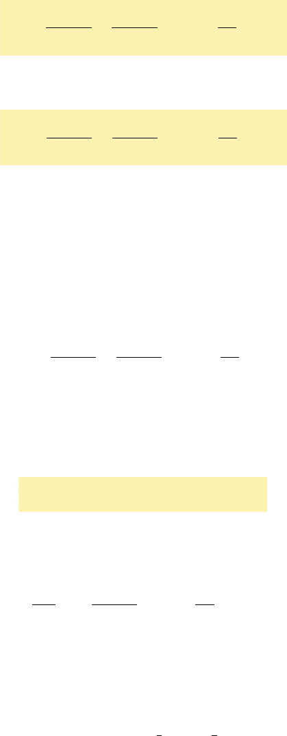
Recalling that the main purpose of this section is to express the
strain components associated with the frame of reference x9y9 of Fig.
7.57 in terms of the angle u and the strain components P
x
, P
y
, and g
xy
associated with the x and y axes, we note that the normal strain P
x9
along the x9 axis is given by Eq. (7.41). Using the trigonometric rela-
tions (7.3) and (7.4), we write this equation in the alternative form
P
x¿
5
P
x
1
P
y
2
1
P
x
2 P
y
2
cos 2u 1
g
xy
2
sin 2u
(7.44)
Replacing u by u 1 908, we obtain the normal strain along the y9 axis.
Since cos (2u 1 1808) 5 2cos 2u and sin (2u 1 1808) 5 2sin 2u, we
have
P
y¿
5
P
x
1
P
y
2
2
P
x
2 P
y
2
cos 2u 2
g
xy
2
sin 2u
(7.45)
Adding Eqs. (7.44) and (7.45) member to member, we obtain
P
x¿
1
P
y
¿
5 P
x
1
P
y
(7.46)
Since P
z
5 P
z9
5 0, we thus verify in the case of plane strain that
the sum of the normal strains associated with a cubic element of
material is independent of the orientation of that element.†
Replacing now u by u 1 458 in Eq. (7.44), we obtain an expres-
sion for the normal strain along the bisector OB9 of the angle formed
by the x9 and y9 axes. Since cos (2u 1 908) 5 2sin 2u and sin (2u 1
908) 5 cos 2u, we have
P
OB¿
5
P
x
1
P
y
2
2
P
x
2 P
y
2
sin 2u 1
g
xy
2
cos 2u
(7.47)
Writing Eq. (7.43) with respect to the x9 and y9 axes, we express the
shearing strain g
x9y9
in terms of the normal strains measured along
the x9 and y9 axes and the bisector OB9:
g
x¿
y
¿
5 2P
OB¿
2
1
P
x¿
1 P
y
¿
2
(7.48)
Substituting from Eqs. (7.46) and (7.47) into (7.48), we obtain
g
x¿
y
¿
52
1
P
x
2 P
y
2
sin 2u 1 g
x
y
cos 2u (7.49)
Equations (7.44), (7.45), and (7.49) are the desired equations
defining the transformation of plane strain under a rotation of axes
in the plane of strain. Dividing all terms in Eq. (7.49) by 2, we write
this equation in the alternative form
g
x¿y¿
2
52
P
x
2 P
y
2
sin 2u 1
g
xy
2
cos 2u
(7.499)
and observe that Eqs. (7.44), (7.45), and (7.499) for the transforma-
tion of plane strain closely resemble the equations derived in Sec.
7.2 for the transformation of plane stress. While the former may be
obtained from the latter by replacing the normal stresses by the cor-
responding normal strains, it should be noted, however, that the
shearing stresses t
xy
and t
x9y9
should be replaced by half of the cor-
responding shearing strains, i.e., by
1
2
g
x
y
and
1
2
g
x¿
y
¿
, respectively.
†Cf. first footnote on page 97.
bee80288_ch07_436-511.indd Page 488 11/17/10 11:16:08 PM user-f499bee80288_ch07_436-511.indd Page 488 11/17/10 11:16:08 PM user-f499 /Users/user-f499/Desktop/Temp Work/Don't Delete Job/MHDQ251:Beer:201/ch07/Users/user-f499/Desktop/Temp Work/Don't Delete Job/MHDQ251:Beer:201/ch07
Apago PDF Enhancer
489
*7.11 MOHR’S CIRCLE FOR PLANE STRAIN
Since the equations for the transformation of plane strain are of the
same form as the equations for the transformation of plane stress,
the use of Mohr’s circle can be extended to the analysis of plane
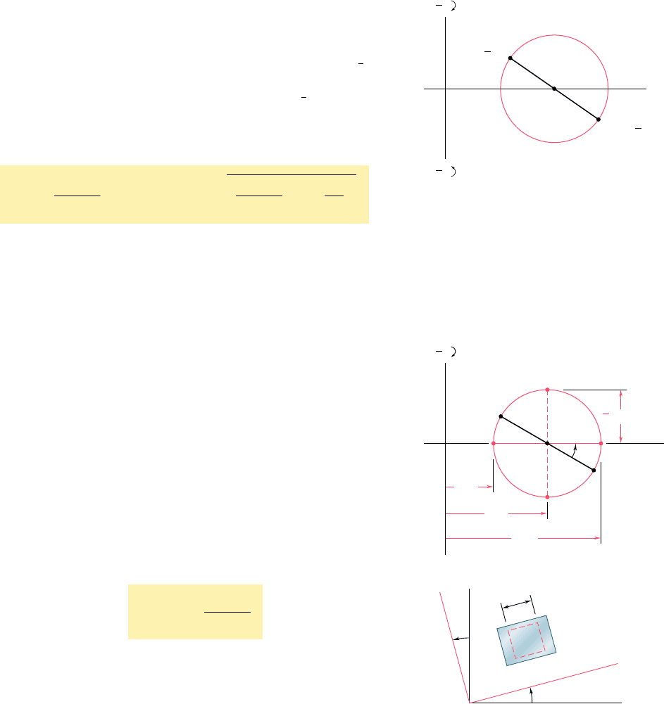
strain. Given the strain components P
x
, P
y
, and g
xy
defining the defor-
mation represented in Fig. 7.56, we plot a point X1P
x
,2
1
2
g
x
y
2 of
abscissa equal to the normal strain P
x
and of ordinate equal to minus
half the shearing strain g
xy
, and a point Y1P
y
, 1
1
2
g
x
y
2 (Fig. 7.60).
Drawing the diameter XY, we define the center C of Mohr’s circle
for plane strain. The abscissa of C and the radius R of the circle are
respectively equal to
P
ave
5
P
x
1
P
y
2
and
R 5
B
a
P
x
2 P
y
2
b
2
1
a
g
xy
2
b
2
(7.50)
We note that if g
xy
is positive, as assumed in Fig. 7.56, points
X and Y are plotted, respectively, below and above the horizontal axis
in Fig. 7.60. But, in the absence of any overall rigid-body rotation,
the side of the element in Fig. 7.56 that is associated with P
x
is
observed to rotate counterclockwise, while the side associated with
P
y
is observed to rotate clockwise. Thus, if the shear deformation
causes a given side to rotate clockwise, the corresponding point on
Mohr’s circle for plane strain is plotted above the horizontal axis, and
if the deformation causes the side to rotate counterclockwise, the
corresponding point is plotted below the horizontal axis. We note
that this convention matches the convention used to draw Mohr’s
circle for plane stress.
Points A and B where Mohr’s circle intersects the horizontal
axis correspond to the principal strains P
max
and P
min
(Fig. 7.61a).
We find
P
max
5 P
ave
1 R and P
min
5 P
ave
2 R (7.51)
where P
ave
and R are defined by Eqs. (7.50). The corresponding value
u
p
of the angle u is obtained by observing that the shearing strain is
zero for A and B. Setting g
x9y9
5 0 in Eq. (7.49), we have
tan 2u
p
5
g
xy
P
x
2 P
y
(7.52)
The corresponding axes a and b in Fig. 7.61b are the principal axes
of strain. The angle u
p
, which defines the direction of the principal
axis Oa in Fig. 7.61b corresponding to point A in Fig. 7.61a, is equal
to half of the angle XCA measured on Mohr’s circle, and the rotation
that brings Ox into Oa has the same sense as the rotation that brings
the diameter XY of Mohr’s circle into the diameter AB.
We recall from Sec. 2.14 that, in the case of the elastic defor-
mation of a homogeneous, isotropic material, Hooke’s law for shear-
ing stress and strain applies and yields t
xy
5 Gg
xy
for any pair of
rectangular x and y axes. Thus, g
xy
5 0 when t
xy
5 0, which indi-
cates that the principal axes of strain coincide with the principal axes
of stress.
7.11 Mohr’s Circle for Plane Strain
()
y
,Y
C
O
xy
2
1
()
x
,X
xy
2
1
1
2
1
2
Fig. 7.60 Mohr’s circle for plane strain.
s (1
s
min
)
s (1
max
)
C
O
max (in plane)
p
min
ave
max
2
1
X
2
p
p
A
b
a
B
Y
y
x
D
E
1
2
(a)
(b)
Fig. 7.61 Principal strain determination.
bee80288_ch07_436-511.indd Page 489 10/30/10 3:32:51 PM user-f499bee80288_ch07_436-511.indd Page 489 10/30/10 3:32:51 PM user-f499/Users/user-f499/Desktop/Temp Work/Don't Delete Job/MHDQ251:Beer:201/ch07/Users/user-f499/Desktop/Temp Work/Don't Delete Job/MHDQ251:Beer:201/ch
Apago PDF Enhancer
490
Transformations of Stress and Strain
The maximum in-plane shearing strain is defined by points D
and E in Fig. 7.61a. It is equal to the diameter of Mohr’s circle.
Recalling the second of Eqs. (7.50), we write
g
max 1in
p
lane2
5 2R 5 21P
x
2 P
y
2
2
1 g
2
x
y
(7.53)
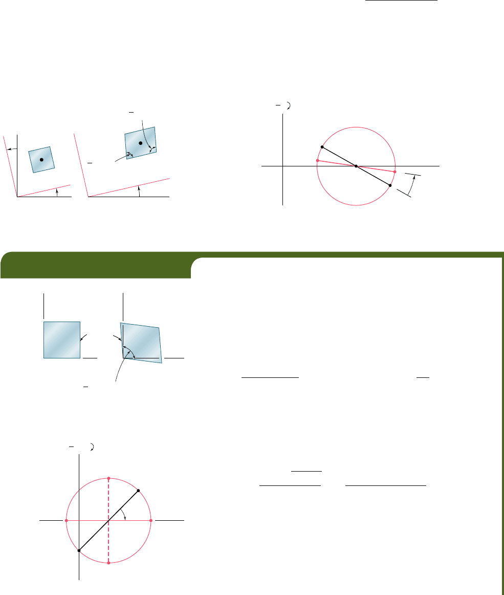
Finally, we note that the points X9 and Y9 that define the compo-
nents of strain corresponding to a rotation of the coordinate axes through
an angle u (Fig. 7.57) are obtained by rotating the diameter XY of
Mohr’s circle in the same sense through an angle 2u (Fig. 7.62).
Q
Q
s
s
s (1 )
y'
s (1 )
x'
y
x
O
x
O
x'y'
2
x'y'
2
y
'
y'
x
'
x'
Fig. 7.57 (repeated)
CO
X
2
Y
Y'
X'
1
2
Fig. 7.62
EXAMPLE 7.04
In a material in a state of plane strain, it is known that the horizontal
side of a 10 3 10-mm square elongates by 4 mm, while its vertical side
remains unchanged, and that the angle at the lower left corner increases
by 0.4 3 10
23
rad (Fig. 7.63). Determine (a) the principal axes and prin-
cipal strains, (b) the maximum shearing strain and the corresponding
normal strain.
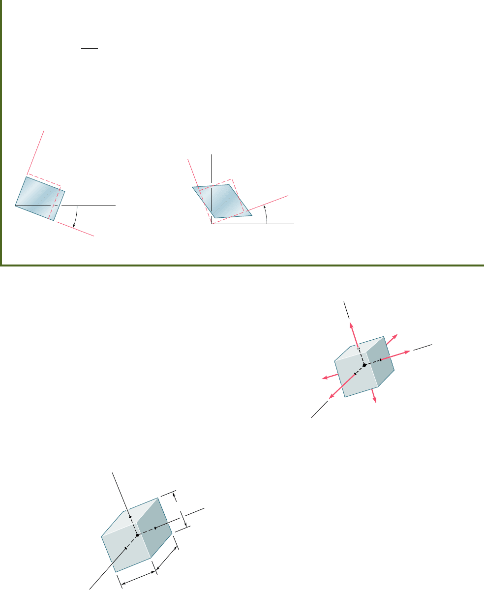
(a) Principal Axes and Principal Strains. We first determine
the coordinates of points X and Y on Mohr’s circle for strain. We have
P
x
5
14 3 10
2
6
m
10 3 10
3
m
51400 m
P
y
5 0
`
g
xy
2
`
5 200 m
Since the side of the square associated with P
x
rotates clockwise, point X
of coordinates P
x
and |g
xy
y2| is plotted above the horizontal axis. Since
P
y
5 0 and the corresponding side rotates counterclockwise, point Y is
plotted directly below the origin (Fig. 7.64). Drawing the diameter XY,
we determine the center C of Mohr’s circle and its radius R. We have
OC 5
P
x
1
P
y
2
5 200 m
O
Y 5
200
m
R 5 2
1
OC
2
2
1
1
OY
2
2
5 2
1
200 m
2
2
1
1
200 m
2
2
5 283 m
The principal strains are defined by the abscissas of points A and B. We
write
P
a
5
OA
5
OC
1 R 5
200
m
1
283
m
5
483
m
P
b
5
O
B 5
OC
2 R 5
200
m
2
283
m
52
83
m
The principal axes Oa and Ob are shown in Fig. 7.65. Since OC 5 OY,
the angle at C in triangle OCY is 458. Thus, the angle 2u
p
that brings XY
into AB is 458i and the angle u
p
bringing Ox into Oa is 22.58i.
0.4 10
–3
rad
2
10 mm
10 mm
10 mm 4m
xx
y
y
Fig. 7.63
X(400, 200)
Y(0, 200)
CO
p
2
A
B
D
E
1
2
(
)
(
)
Fig. 7.64
bee80288_ch07_436-511.indd Page 490 10/30/10 7:35:31 PM user-f499bee80288_ch07_436-511.indd Page 490 10/30/10 7:35:31 PM user-f499 /Users/user-f499/Desktop/Temp Work/Don't Delete Job/MHDQ251:Beer:201/ch07/Users/user-f499/Desktop/Temp Work/Don't Delete Job/MHDQ251:Beer:201/ch07
Apago PDF Enhancer
491
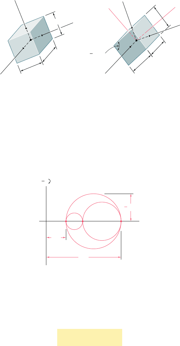
*7.12 THREE-DIMENSIONAL ANALYSIS OF STRAIN
We saw in Sec. 7.5 that, in the most general case of stress, we can
determine three coordinate axes a, b, and c, called the principal axes of
stress. A small cubic element with faces respectively perpendicular to
these axes is free of shearing stresses (Fig. 7.25); i.e., we have t
ab
5
t
bc
5 t
ca
5 0. As recalled in the preceding section, Hooke’s law for
shearing stress and strain applies when the deformation is elastic and
the material homogeneous and isotropic. It follows that, in such a case,
g
ab
5 g
bc
5 g
ca
5 0, i.e., the axes a, b, and c are also principal axes of
strain. A small cube of side equal to unity, centered at Q and with faces
respectively perpendicular to the principal axes, is deformed into a rect-
angular parallelepiped of sides 1 1 P
a
, 1 1 P
b
, and 1 1 P
c
(Fig. 7.67).
(b) Maximum Shearing Strain. Points D and E define the maxi-
mum in-plane shearing strain which, since the principal strains have opposite
signs, is also the actual maximum shearing strain (see Sec. 7.12). We have
g
max
2
5 R 5 283 m
g
max
5 566
m
The corresponding normal strains are both equal to
P
¿
5 OC 5 200
m
The axes of maximum shearing strain are shown in Fig. 7.66.
O
p
22.5
y
x
b
a
Fig. 7.65
O
22.5
y
d
e
x
Fig. 7.66
a
a
b
b
c
c
Q
a
c
b
Fig. 7.25 (repeated)
Q
c
a
b
1
b
1
c
1
a
Fig. 7.67 Principal strains.
7.12 Three-Dimensional Analysis of Strain
bee80288_ch07_436-511.indd Page 491 10/30/10 7:35:32 PM user-f499bee80288_ch07_436-511.indd Page 491 10/30/10 7:35:32 PM user-f499 /Users/user-f499/Desktop/Temp Work/Don't Delete Job/MHDQ251:Beer:201/ch07/Users/user-f499/Desktop/Temp Work/Don't Delete Job/MHDQ251:Beer:201/ch07
Apago PDF Enhancer
492
Transformations of Stress and Strain
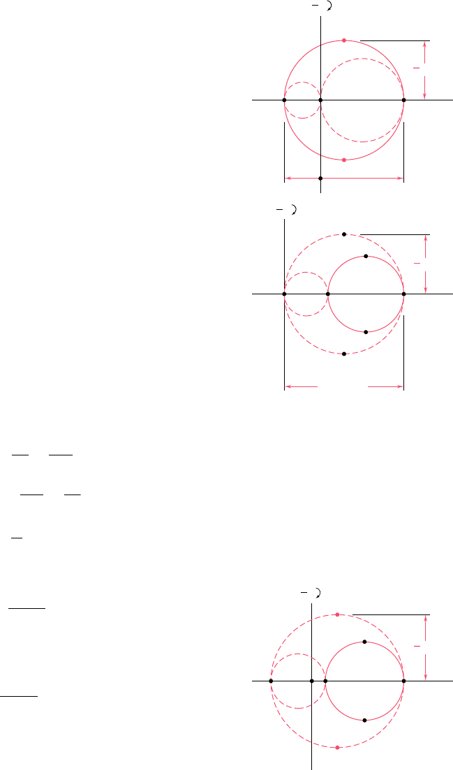
If the element of Fig. 7.67 is rotated about one of the principal
axes at Q, say the c axis (Fig. 7.68), the method of analysis developed
earlier for the transformation of plane strain can be used to deter-
mine the strain components P
x
, P
y
, and g
xy
associated with the faces
perpendicular to the c axis, since the derivation of this method did
not involve any of the other strain components.† We can, therefore,
draw Mohr’s circle through the points A and B corresponding to the
principal axes a and b (Fig. 7.69). Similarly, circles of diameters BC
and CA can be used to analyze the transformation of strain as the
element is rotated about the a and b axes, respectively.
Q
c
a
b
1
b
1
c
1
a
Fig. 7.67 (repeated)
z c
Q
a
b
y
x
1
x
1
c
1
y
xy
2
Fig. 7.68
†We note that the other four faces of the element remain rectangular and that the edges
parallel to the c axis remain unchanged.
O CB
A
min
max
max
1
2
1
2
Fig. 7.69 Mohr’s circle for three-
dimensional analysis of strain.
The three-dimensional analysis of strain by means of Mohr’s
circle is limited here to rotations about principal axes (as was the
case for the analysis of stress) and is used to determine the maximum
shearing strain g
max
at point Q. Since g
max
is equal to the diameter
of the largest of the three circles shown in Fig. 7.69, we have
g
max
5
0
P
max
2 P
min
0
(7.54)
where P
max
and P
min
represent the algebraic values of the maximum
and minimum strains at point Q.
bee80288_ch07_436-511.indd Page 492 10/30/10 3:33:11 PM user-f499bee80288_ch07_436-511.indd Page 492 10/30/10 3:33:11 PM user-f499/Users/user-f499/Desktop/Temp Work/Don't Delete Job/MHDQ251:Beer:201/ch07/Users/user-f499/Desktop/Temp Work/Don't Delete Job/MHDQ251:Beer:201/ch
Apago PDF Enhancer
493
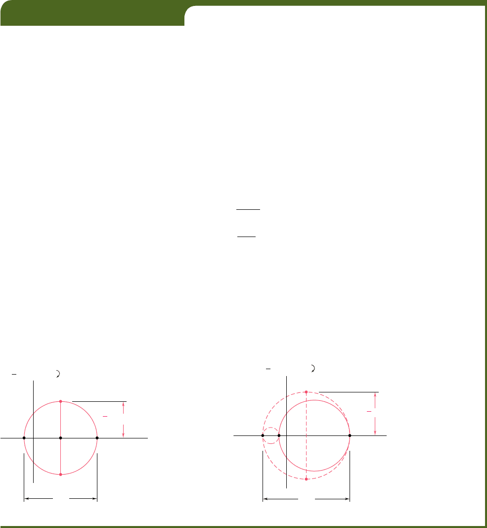
Returning to the particular case of plane strain, and selecting
the x and y axes in the plane of strain, we have P
z
5 g
zx
5 g
zy
5 0.
Thus, the z axis is one of the three principal axes at Q, and the cor-
responding point in the Mohr-circle diagram is the origin O, where
P 5 g 5 0. If the points A and B that define the principal axes within
the plane of strain fall on opposite sides of O (Fig. 7.70a), the cor-
responding principal strains represent the maximum and minimum
normal strains at point Q, and the maximum shearing strain is equal
to the maximum in-plane shearing strain corresponding to points D
and E. If, on the other hand, A and B are on the same side of O
(Fig. 7.70b), that is, if P
a
and P
b
have the same sign, then the maxi-
mum shearing strain is defined by points D9 and E9 on the circle of
diameter OA, and we have g
max
5 P
max
.
We now consider the particular case of plane stress encoun-
tered in a thin plate or on the free surface of a structural element
or machine component (Sec. 7.1). Selecting the x and y axes in the
plane of stress, we have s
z
5 t
zx
5 t
zy
5 0 and verify that the z axis
is a principal axis of stress. As we saw earlier, if the deformation is
elastic and if the material is homogeneous and isotropic, it follows
from Hooke’s law that g
zx
5 g
zy
5 0; thus, the z axis is also a principal
axis of strain, and Mohr’s circle can be used to analyze the transfor-
mation of strain in the xy plane. However, as we shall see presently,
it does not follow from Hooke’s law that P
z
5 0; indeed, a state of
plane stress does not, in general, result in a state of plane strain.†
Denoting by a and b the principal axes within the plane of
stress, and by c the principal axis perpendicular to that plane, we let
s
x
5 s
a
, s
y
5 s
b
, and s
z
5 0 in Eqs. (2.28) for the generalized
Hooke’s law (Sec. 2.12) and write
P
a
5
s
a
E
2
ns
b
E
(7.55)
P
b
52
ns
a
E
1
s
b
E
(7.56)
P
c
52
n
E
1s
a
1 s
b
2
(7.57)
Adding Eqs. (7.55) and (7.56) member to member, we have
P
a
1 P
b
5
1 2 n
E
1s
a
1 s
b
2
(7.58)
Solving Eq. (7.58) for s
a
1 s
b
and substituting into Eq. (7.57), we
write
P
c
52
n
1 2 n
1P
a
1 P
b
2
(7.59)
The relation obtained defines the third principal strain in terms of
the “in-plane’’ principal strains. We note that, if B is located between
A and C on the Mohr-circle diagram (Fig. 7.71), the maximum shear-
ing strain is equal to the diameter CA of the circle corresponding to
a rotation about the b axis, out of the plane of stress.
7.12 Three-Dimensional Analysis of Strain
†See footnote on page 486.
Z ⫽ OB
D
E
␥
A
min
⑀
max
max
⑀
⑀
1
2
␥
1
2
(a)
Z ⫽ OB
E
D
D'
E'
␥
A
min
⫽ 0
⑀
max
⫽
max
⑀
a
⑀
⑀
1
2
␥
1
2
(b)
Fig. 7.70 Mohr’s circle for plane strain.
OC
B
E
D
D'
E'
␥
A
max
⑀
1
2
␥
1
2
Fig. 7.71 Mohr’s circle strain analysis
for plane stress.
bee80288_ch07_436-511.indd Page 493 11/17/10 11:16:09 PM user-f499bee80288_ch07_436-511.indd Page 493 11/17/10 11:16:09 PM user-f499 /Users/user-f499/Desktop/Temp Work/Don't Delete Job/MHDQ251:Beer:201/ch07/Users/user-f499/Desktop/Temp Work/Don't Delete Job/MHDQ251:Beer:201/ch07
Apago PDF Enhancer
EXAMPLE 7.05
As a result of measurements made on the surface of a machine compo-
nent with strain gages oriented in various ways, it has been established
that the principal strains on the free surface are P
a
5 1400 3 10
26
in./in.
and P
b
5 250 3 10
26
in./in. Knowing that Poisson’s ratio for the given
material is n 5 0.30, determine (a) the maximum in-plane shearing strain,
(b) the true value of the maximum shearing strain near the surface of the
component.
(a) Maximum In-Plane Shearing Strain. We draw Mohr’s circle
through the points A and B corresponding to the given principal strains
(Fig. 7.72). The maximum in-plane shearing strain is defined by points D
and E and is equal to the diameter of Mohr’s circle:
g
max 1in plane2
5 400 3 10
2
6
1 50 3 10
2
6
5 450 3 10
2
6
rad
(b) Maximum Shearing Strain. We first determine the third
principal strain P
c
. Since we have a state of plane stress on the surface of
the machine component, we use Eq. (7.59) and write
P
c
52
n
1 2 n
1P
a
1 P
b
2
52
0
.
30
0
.
70
1400 3 10
26
2 50 3 10
26
252150 3 10
26
in./in.
Drawing Mohr’s circles through A and C and through B and C (Fig. 7.73),
we find that the maximum shearing strain is equal to the diameter of the
circle of diameter CA:
g
max
5 400 3 10
2
6
1 150 3 10
2
6
5 550 3 10
2
6
rad
We note that, even though P
a
and P
b
have opposite signs, the maximum
in-plane shearing strain does not represent the true maximum shearing
strain.
494
Fig. 7.72
O
B
450
⫹400
⫺50
(10
⫺6
rad)
(10
⫺6
in./in.)
E
D
␥
A
max (in plane)
⑀
1
2
␥
1
2
B
D'
E'
A
OC
max
␥
1
2
⫹400
⫺150
550
(10
⫺6
in./in.)
⑀
(10
⫺6
rad)
␥
1
2
Fig. 7.73
*7.13 MEASUREMENTS OF STRAIN; STRAIN ROSETTE
The normal strain can be determined in any given direction on the
surface of a structural element or machine component by scribing
two gage marks A and B across a line drawn in the desired direction
and measuring the length of the segment AB before and after the
bee80288_ch07_436-511.indd Page 494 11/17/10 11:16:15 PM user-f499bee80288_ch07_436-511.indd Page 494 11/17/10 11:16:15 PM user-f499 /Users/user-f499/Desktop/Temp Work/Don't Delete Job/MHDQ251:Beer:201/ch07/Users/user-f499/Desktop/Temp Work/Don't Delete Job/MHDQ251:Beer:201/ch07
Apago PDF Enhancer
495
load has been applied. If L is the undeformed length of AB and d
its deformation, the normal strain along AB is P
AB
5 dyL.
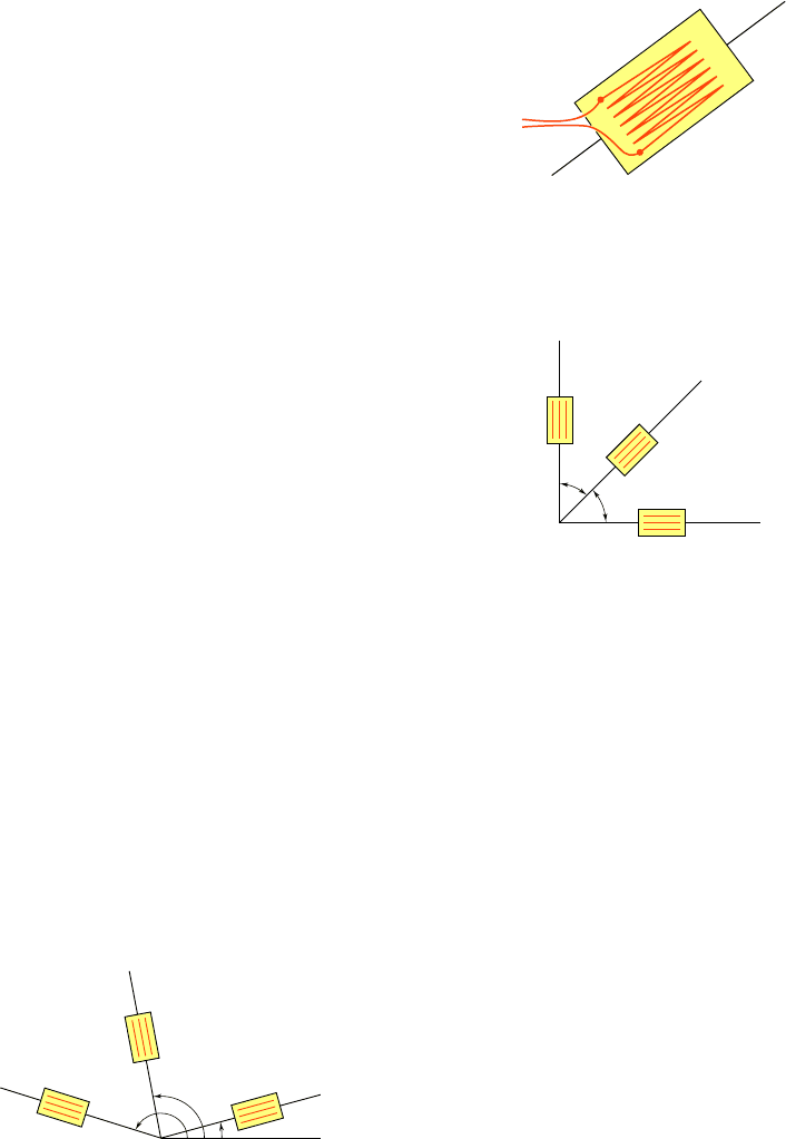
A more convenient and more accurate method for the mea-
surement of normal strains is provided by electrical strain gages. A
typical electrical strain gage consists of a length of thin wire arranged
as shown in Fig. 7.74 and cemented to two pieces of paper. In order
to measure the strain P
AB
of a given material in the direction AB, the
gage is cemented to the surface of the material, with the wire folds
running parallel to AB. As the material elongates, the wire increases
in length and decreases in diameter, causing the electrical resistance
of the gage to increase. By measuring the current passing through a
properly calibrated gage, the strain P
AB
can be determined accurately
and continuously as the load is increased.
The strain components P
x
and P
y
can be determined at a given
point of the free surface of a material by simply measuring the normal
strain along x and y axes drawn through that point. Recalling Eq. (7.43)
of Sec. 7.10, we note that a third measurement of normal strain, made
along the bisector OB of the angle formed by the x and y axes, enables
us to determine the shearing strain g
xy
as well (Fig. 7.75):
g
x
y
5 2P
OB
2
1
P
x
1 P
y
2
(7.43)
It should be noted that the strain components P
x
, P
y
, and g
xy
at
a given point could be obtained from normal strain measurements
made along any three lines drawn through that point (Fig. 7.76). Denot-
ing respectively by u
1
, u
2
, and u
3
the angle each of the three lines forms
with the x axis, by P
1
, P
2
, and P
3
the corresponding strain measurements,
and substituting into Eq. (7.41), we write the three equations
P
1
5 P
x
cos
2
u
1
1 P
y
sin
2
u
1
1 g
x
y
sin u
1
cos u
1
P
2
5 P
x
cos
2
u
2
1 P
y
sin
2
u
2
1 g
x
y
sin u
2
cos u
2
(7.60)
P
3
5 P
x
cos
2
u
3
1 P
y
sin
2
u
3
1 g
x
y
sin u
3
cos u
3
which can be solved simultaneously for P
x
, P
y
, and g
xy
.†
The arrangement of strain gages used to measure the three
normal strains P
1
, P
2
, and P
3
is known as a strain rosette. The rosette
used to measure normal strains along the x and y axes and their
bisector is referred to as a 458 rosette (Fig. 7.75). Another rosette
frequently used is the 608 rosette (see Sample Prob. 7.7).
7.13 Measurements of Strain; Strain Rosette
A
B
Fig. 7.74 Electrical strain gage.
45
B
O
y
x
45
OB
x
y
Fig. 7.75
L
1
L
2
L
3
O
x
2
1
3
2
3
1
Fig. 7.76 Strain rosette.
†It should be noted that the free surface on which the strain measurements are made is
in a state of plane stress, while Eqs. (7.41) and (7.43) were derived for a state of plane
strain. However, as observed earlier, the normal to the free surface is a principal axis of
strain and the derivations given in Sec. 7.10 remain valid.
bee80288_ch07_436-511.indd Page 495 10/30/10 3:33:26 PM user-f499bee80288_ch07_436-511.indd Page 495 10/30/10 3:33:26 PM user-f499/Users/user-f499/Desktop/Temp Work/Don't Delete Job/MHDQ251:Beer:201/ch07/Users/user-f499/Desktop/Temp Work/Don't Delete Job/MHDQ251:Beer:201/ch
Apago PDF Enhancer
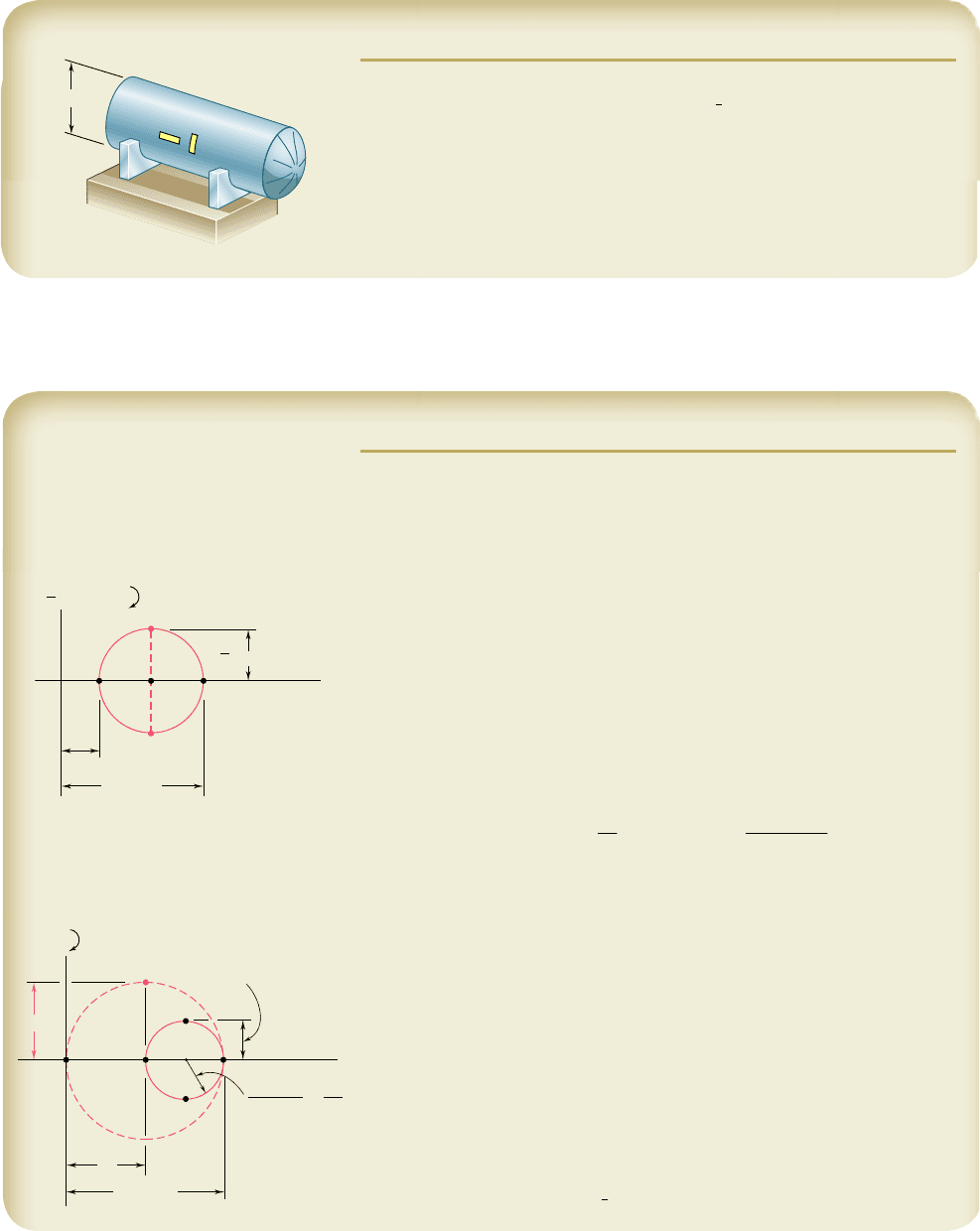
SAMPLE PROBLEM 7.6
A cylindrical storage tank used to transport gas under pressure has an inner
diameter of 24 in. and a wall thickness of
3
4
in. Strain gages attached to
the surface of the tank in transverse and longitudinal directions indicate
strains of 255 3 10
26
and 60 3 10
26
in./in. respectively. Knowing that a
torsion test has shown that the modulus of rigidity of the material used in
the tank is G 5 11.2 3 10
6
psi, determine (a) the gage pressure inside
the tank, (b) the principal stresses and the maximum shearing stress in the
wall of the tank.
24 in.
1
2
SOLUTION
a. Gage Pressure Inside Tank. We note that the given strains are the
principal strains at the surface of the tank. Plotting the corresponding points
A and B, we draw Mohr’s circle for strain. The maximum in-plane shearing
strain is equal to the diameter of the circle.
g
max 1in plane2
5 P
1
2 P
2
5 255 3 10
2
6
2 60 3 10
2
6
5 195 3 10
2
6
rad
From Hooke’s law for shearing stress and strain, we have
t
max 1in plane2
5 Gg
max 1in plane2
5 111.2 3 10
6
psi21195 3 10
2
6
rad2
5 2184 psi 5 2.184
k
si
Substituting this value and the given data in Eq. (7.33), we write
t
max 1in plane2
5
pr
4
t
2184 psi 5
p
1
12 in.
2
4
1
0.75 in.
2
Solving for the gage pressure p, we have
p 5 546 psi
◀
b. Principal Stresses and Maximum Shearing Stress. Recalling that,
for a thin-walled cylindrical pressure vessel, s
1
5 2s
2
, we draw Mohr’s circle
for stress and obtain
s
2
5 2t
max 1in plane2
5 2
1
2.184 ksi
2
5 4.368 ksi s
2
5 4.37
k
si
◀
s
1
5 2s
2
5 2
1
4.368 ksi
2
s
1
5 8.74
k
si
◀
The maximum shearing stress is equal to the radius of the circle of diameter
OA and corresponds to a rotation of 458 about a longitudinal axis.
t
max
5
1
2
s
1
5 s
2
5 4.368 ksi t
m
a
x
5 4.37
k
si
◀
A
CB
1
255
(10
–6
in./in.)
(10
–6
rad)
2
D
E
O
max (in plane)
2
60
1
2
22
A
E
B
1
2
D
2.184 ksi
D'
O
max
1
2
2
2
2
max (in plane)
496
bee80288_ch07_436-511.indd Page 496 10/30/10 3:33:33 PM user-f499bee80288_ch07_436-511.indd Page 496 10/30/10 3:33:33 PM user-f499/Users/user-f499/Desktop/Temp Work/Don't Delete Job/MHDQ251:Beer:201/ch07/Users/user-f499/Desktop/Temp Work/Don't Delete Job/MHDQ251:Beer:201/ch
