Beer F.P., Johnston E.R., DeWolf J.T., Mazurek D.F. Mechanics of Materials
Подождите немного. Документ загружается.


Apago PDF Enhancer
CHAPTER
437
Transformations of
Stress and Strain
bee80288_ch07_436-511.indd Page 437 10/30/10 1:36:46 AM user-f499bee80288_ch07_436-511.indd Page 437 10/30/10 1:36:46 AM user-f499 /Users/user-f499/Desktop/Temp Work/Don't Delete Job/MHDQ251:Beer:201/ch07/Users/user-f499/Desktop/Temp Work/Don't Delete Job/MHDQ251:Beer:201/ch07
Apago PDF Enhancer
438
Chapter 7 Transformations of
Stress and Strain
7.1 Introduction
7.2 Transformation of Plane Stress
7.3 Principal Stresses; Maximum
Shearing Stress
7.4 Mohr’s Circle for Plane Stress
7.5 General State of Stress
7.6 Application of Mohr’s Circle to
the Three-Dimensional Analysis
of Stress
*7.7 Yield Criteria for Ductile
Materials under Plane Stress
*7.8 Fracture Criteria for Brittle
Materials under Plane Stress
7.9 Stresses in Thin-Walled Pressure
Vessels
*7.10 Transformation of Plane Strain
*7.11 Mohr’s Circle for Plane Strain
*7.12 Three-Dimensional Analysis of
Strain
*7.13 Measurements of Strain; Strain
Rosette
7.1 INTRODUCTION
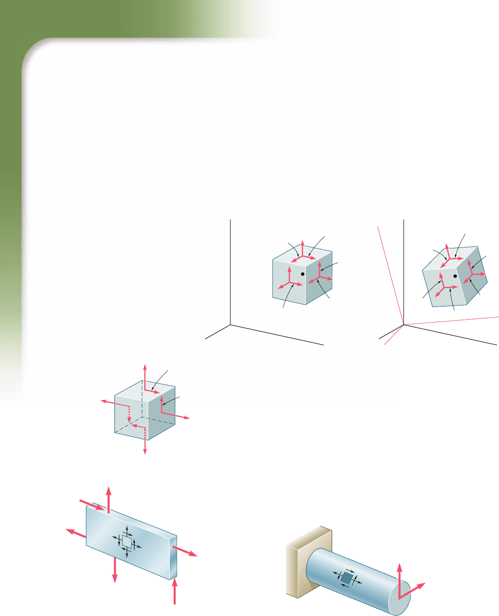
We saw in Sec. 1.12 that the most general state of stress at a given
point Q may be represented by six components. Three of these com-
ponents, s
x
, s
y
, and s
z
, define the normal stresses exerted on the faces
of a small cubic element centered at Q and of the same orientation as
the coordinate axes (Fig. 7.1a), and the other three, t
xy
, t
yz
, and t
zx
,†
the components of the shearing stresses on the same element. As we
remarked at the time, the same state of stress will be represented by
a different set of components if the coordinate axes are rotated
(Fig. 7.1b). We propose in the first part of this chapter to determine
how the components of stress are transformed under a rotation of the
coordinate axes. The second part of the chapter will be devoted to a
similar analysis of the transformation of the components of strain.
Our discussion of the transformation of stress will deal mainly
with plane stress, i.e., with a situation in which two of the faces of
the cubic element are free of any stress. If the z axis is chosen per-
pendicular to these faces, we have s
z
5 t
zx
5 t
zy
5 0, and the only
remaining stress components are s
x
, s
y
, and t
xy
(Fig. 7.2). Such a
situation occurs in a thin plate subjected to forces acting in the mid-
plane of the plate (Fig. 7.3). It also occurs on the free surface of a
structural element or machine component, i.e., at any point of the
surface of that element or component that is not subjected to an
external force (Fig. 7.4).
†We recall that t
yx
5 t
xy
, t
zy
5 t
yz
, and t
xz
5 t
zx
.
yz
yx
xy
xz
zx
zy
y
y'z'
y'x'
x'z'
z'x'
z'y'
x'y'
y'
x'
z
x
Q
O
z
y
x
(a)
O
z
z'
y'
y
x
x
'
(b)
z'
Q
Fig. 7.1 General state of stress at a point.
yx
xy
y
x
Fig. 7.2 Plane stress.
F
1
F
2
F
3
F
4
F
5
F
6
Fig. 7.3 Example of plane stress.
F
1
F
2
Fig. 7.4 Example of plane stress.
bee80288_ch07_436-511.indd Page 438 10/30/10 1:36:52 AM user-f499bee80288_ch07_436-511.indd Page 438 10/30/10 1:36:52 AM user-f499 /Users/user-f499/Desktop/Temp Work/Don't Delete Job/MHDQ251:Beer:201/ch07/Users/user-f499/Desktop/Temp Work/Don't Delete Job/MHDQ251:Beer:201/ch07
Apago PDF Enhancer
439
7.1 Introduction
xy
x'y'
y
y'
x
x'
Q
Q
z
xx
x
'
y
y'
z' z
y
(a)(b)
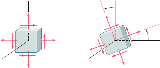
Fig. 7.5 Transformation of stress.
Considering in Sec. 7.2 a state of plane stress at a given point
Q characterized by the stress components s
x
, s
y
, and t
xy
associated
with the element shown in Fig. 7.5a, you will learn to determine the
components s
x9
, s
y9
, and t
x9y9
associated with that element after it
has been rotated through an angle u about the z axis (Fig. 7.5b). In
Sec. 7.3, you will determine the value u
p
of u for which the stresses
s
x9
and s
y9
are, respectively, maximum and minimum; these values
of the normal stress are the principal stresses at point Q, and the
faces of the corresponding element define the principal planes of
stress at that point. You will also determine the value u
s
of the angle
of rotation for which the shearing stress is maximum, as well as the
value of that stress.
In Sec. 7.4, an alternative method for the solution of problems
involving the transformation of plane stress, based on the use of
Mohr’s circle, will be presented.
In Sec. 7.5, the three-dimensional state of stress at a given point
will be considered and a formula for the determination of the normal
stress on a plane of arbitrary orientation at that point will be devel-
oped. In Sec. 7.6, you will consider the rotations of a cubic element
about each of the principal axes of stress and note that the corre-
sponding transformations of stress can be described by three differ-
ent Mohr’s circles. You will also observe that, in the case of a state
of plane stress at a given point, the maximum value of the shearing
stress obtained earlier by considering rotations in the plane of stress
does not necessarily represent the maximum shearing stress at that
point. This will bring you to distinguish between in-plane and out-
of-plane maximum shearing stresses.
Yield criteria for ductile materials under plane stress will be
developed in Sec. 7.7. To predict whether a material will yield at
some critical point under given loading conditions, you will deter-
mine the principal stresses s
a
and s
b
at that point and check whether
s
a
, s
b
, and the yield strength s
Y
of the material satisfy some crite-
rion. Two criteria in common use are: the maximum-shearing-strength
criterion and the maximum-distortion-energy criterion. In Sec. 7.8,
fracture criteria for brittle materials under plane stress will be devel-
oped in a similar fashion; they will involve the principal stresses s
a
and s
b
at some critical point and the ultimate strength s
U
of the
bee80288_ch07_436-511.indd Page 439 10/30/10 1:37:04 AM user-f499bee80288_ch07_436-511.indd Page 439 10/30/10 1:37:04 AM user-f499 /Users/user-f499/Desktop/Temp Work/Don't Delete Job/MHDQ251:Beer:201/ch07/Users/user-f499/Desktop/Temp Work/Don't Delete Job/MHDQ251:Beer:201/ch07
Apago PDF Enhancer
440
Transformations of Stress and Strain
material. Two criteria will be discussed: the maximum-normal-stress
criterion and Mohr’s criterion.
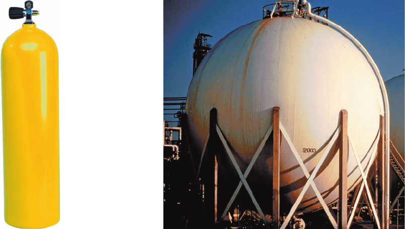
Thin-walled pressure vessels provide an important application
of the analysis of plane stress. In Sec. 7.9, we will discuss stresses in
both cylindrical and spherical pressure vessels (Photos 7.1 and 7.2).
Photo 7.1
Cylindrical
pressure vessel.
Photo 7.2 Spherical pressure vessel.
Sections 7.10 and 7.11 will be devoted to a discussion of the
transformation of plane strain and to Mohr’s circle for plane strain.
In Sec. 7.12, we will consider the three-dimensional analysis of strain
and see how Mohr’s circles can be used to determine the maximum
shearing strain at a given point. Two particular cases are of special
interest and should not be confused: the case of plane strain and the
case of plane stress.
Finally, in Sec. 7.13, we discuss the use of strain gages to mea-
sure the normal strain on the surface of a structural element or
machine component. You will see how the components P
x
, P
y
, and
g
xy
characterizing the state of strain at a given point can be computed
from the measurements made with three strain gages forming a
strain rosette.
7.2 TRANSFORMATION OF PLANE STRESS
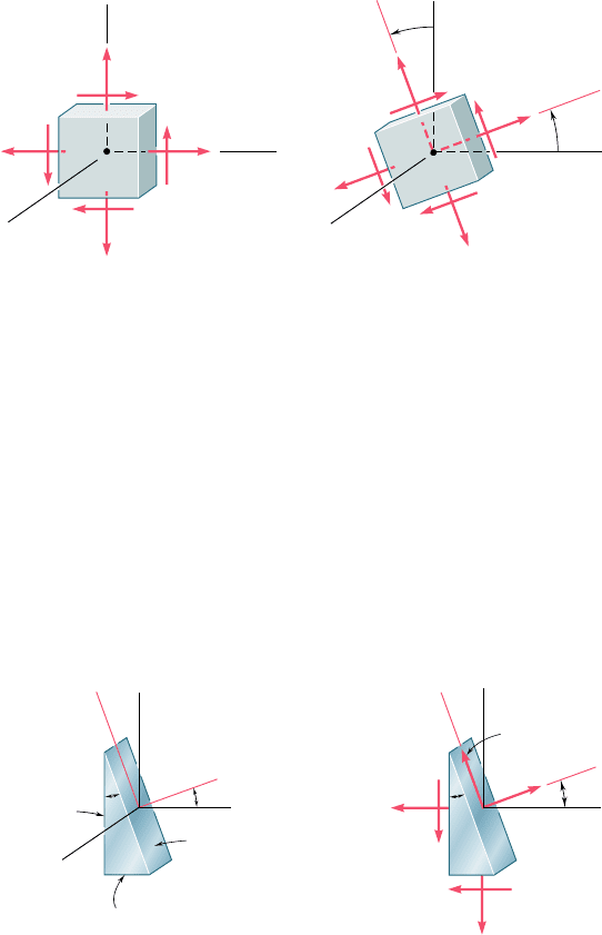
Let us assume that a state of plane stress exists at point Q (with s
z
5
t
zx
5 t
zy
5 0), and that it is defined by the stress components s
x
,
s
y
, and t
xy
associated with the element shown in Fig. 7.5a. We pro-
pose to determine the stress components s
x9
, s
y9
, and t
x9y9
associated
with the element after it has been rotated through an angle u about
bee80288_ch07_436-511.indd Page 440 10/30/10 7:30:35 PM user-f499bee80288_ch07_436-511.indd Page 440 10/30/10 7:30:35 PM user-f499 /Users/user-f499/Desktop/Temp Work/Don't Delete Job/MHDQ251:Beer:201/ch07/Users/user-f499/Desktop/Temp Work/Don't Delete Job/MHDQ251:Beer:201/ch07
Apago PDF Enhancer
441
the z axis (Fig. 7.5b), and to express these components in terms of
s
x
, s
y
, t
xy
, and u.
In order to determine the normal stress s
x9
and the shearing
stress t
x9y9
exerted on the face perpendicular to the x9 axis, we con-
sider a prismatic element with faces respectively perpendicular to
the x, y, and x9 axes (Fig. 7.6a). We observe that, if the area of the
7.2 Transformation of Plane Stress
xy
x'y'
y
y'
x
x'
Q
Q
z
xx
x
'
y
y'
z' z
y
(a)(b)
Fig. 7.5 (repeated)
z
x
x'
y'
y
(a)
A cos
A sin
A
x
x
'
y'
y
(b)
(A cos )
(A cos )
x'y'
A
xy
(A sin )
xy
x'
A
x
(A sin )
y
Fig. 7.6
oblique face is denoted by DA, the areas of the vertical and horizon-
tal faces are respectively equal to DA cos u and DA sin u. It follows
that the forces exerted on the three faces are as shown in Fig. 7.6b.
(No forces are exerted on the triangular faces of the element, since
the corresponding normal and shearing stresses have all been assumed
equal to zero.) Using components along the x9 and y9 axes, we write
the following equilibrium equations:
g
F
x¿
5 0:s
x¿
¢A 2 s
x
1
¢A cos u
2
cos u 2 t
x
y
1
¢A cos u
2
sin u
2s
y
1
¢A sin u
2
sin u 2 t
x
y
1
¢A sin u
2
cos u 5 0
g
F
y
¿
5 0:t
x¿
y
¿
¢A 1 s
x
1
¢A cos u
2
sin u 2 t
x
y
1
¢A cos u
2
cos u
2s
y
1
¢A sin u
2
cos u 1 t
x
y
1
¢A sin u
2
sin u 5 0
bee80288_ch07_436-511.indd Page 441 10/30/10 1:37:09 AM user-f499bee80288_ch07_436-511.indd Page 441 10/30/10 1:37:09 AM user-f499 /Users/user-f499/Desktop/Temp Work/Don't Delete Job/MHDQ251:Beer:201/ch07/Users/user-f499/Desktop/Temp Work/Don't Delete Job/MHDQ251:Beer:201/ch07
Apago PDF Enhancer
442
Transformations of Stress and Strain
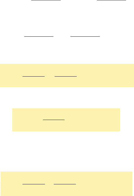
Solving the first equation for s
x9
and the second for t
x9y9
, we have
s
x¿
5 s
x
cos
2
u 1 s
y
sin
2
u 1 2t
xy
sin u cos u (7.1)
t
x¿y¿
521s
x
2 s
y
2 sin u cos u 1 t
xy
1cos
2
u 2 sin
2
u2 (7.2)
Recalling the trigonometric relations
sin 2u 5 2 sin u cos u
cos 2u 5 cos
2
u 2 sin
2
u (7.3)
and
cos
2
u 5
1 1 cos 2u
2
sin
2
u 5
1 2 cos 2u
2
(7.4)
we write Eq. (7.1) as follows:
s
x¿
5 s
x
1 1 cos 2u
2
1 s
y
1 2 cos 2u
2
1 t
xy
sin 2u
or
s
x¿
5
s
x
1 s
y
2
1
s
x
2 s
y
2
cos 2u 1 t
xy
sin 2u
(7.5)
Using the relations (7.3), we write Eq. (7.2) as
t
x¿y¿
52
s
x
2
s
y
2
sin 2u 1 t
xy
cos 2u
(7.6)
The expression for the normal stress s
y9
is obtained by replacing u in
Eq. (7.5) by the angle u 1 908 that the y9 axis forms with the x axis.
Since cos (2u 1 1808) 5 2cos 2u and sin (2u 1 1808) 5 2sin 2u, we
have
s
y¿
5
s
x
1 s
y
2
2
s
x
2 s
y
2
cos 2u 2 t
xy
sin 2u
(7.7)
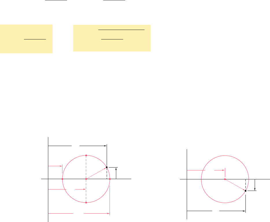
Adding Eqs. (7.5) and (7.7) member to member, we obtain
s
x¿
1 s
y¿
5 s
x
1 s
y
(7.8)
Since s
z
5 s
z9
5 0, we thus verify in the case of plane stress that
the sum of the normal stresses exerted on a cubic element of mate-
rial is independent of the orientation of that element.†
†Cf. first footnote on page 97.
bee80288_ch07_436-511.indd Page 442 11/17/10 11:10:19 PM user-f499bee80288_ch07_436-511.indd Page 442 11/17/10 11:10:19 PM user-f499 /Users/user-f499/Desktop/Temp Work/Don't Delete Job/MHDQ251:Beer:201/ch07/Users/user-f499/Desktop/Temp Work/Don't Delete Job/MHDQ251:Beer:201/ch07
Apago PDF Enhancer
443
7.3 PRINCIPAL STRESSES; MAXIMUM
SHEARING STRESS
The equations (7.5) and (7.6) obtained in the preceding section are
the parametric equations of a circle. This means that, if we choose
a set of rectangular axes and plot a point M of abscissa s
x9
and ordi-
nate t
x9y9
for any given value of the parameter u, all the points thus
obtained will lie on a circle. To establish this property we eliminate
u from Eqs. (7.5) and (7.6); this is done by first transposing (s
x
1 s
y
)/2
in Eq. (7.5) and squaring both members of the equation, then squar-
ing both members of Eq. (7.6), and finally adding member to mem-
ber the two equations obtained in this fashion. We have
as
x¿
2
s
x
1 s
y
2
b
2
1 t
x¿y¿
2
5 a
s
x
2 s
y
2
b
2
1 t
xy
2
(7.9)
Setting
s
ave
5
s
x
1 s
y
2
and
R 5
B
a
s
x
2 s
y
2
b
2
1 t
xy
2
(7.10)
we write the identity (7.9) in the form
1s
x¿
2 s
ave
2
2
1 t
x¿y¿
2
5 R
2
(7.11)
which is the equation of a circle of radius R centered at the point C
of abscissa s
ave
and ordinate 0 (Fig. 7.7). It can be observed that,
due to the symmetry of the circle about the horizontal axis, the same
result would have been obtained if, instead of plotting M, we had
plotted a point N of abscissa s
x9
and ordinate 2t
x9y9
(Fig. 7.8). This
property will be used in Sec. 7.4.
7.3 Principal Stresses; Maximum
Shearing Stress
x'y'
x'y'
x'
x'
ave
C
O
R
N
Fig. 7.8 Equivalent formation of stress
transformation circle.
Fig. 7.7 Circular relationship of
transformed stresses.
x'y'
x'y'
x'
x'
min
max
ave
D
E
C
B
A
O
M
R
The two points A and B where the circle of Fig. 7.7 intersects
the horizontal axis are of special interest: Point A corresponds to the
maximum value of the normal stress s
x9
, while point B corresponds
bee80288_ch07_436-511.indd Page 443 11/17/10 11:10:21 PM user-f499bee80288_ch07_436-511.indd Page 443 11/17/10 11:10:21 PM user-f499 /Users/user-f499/Desktop/Temp Work/Don't Delete Job/MHDQ251:Beer:201/ch07/Users/user-f499/Desktop/Temp Work/Don't Delete Job/MHDQ251:Beer:201/ch07
Apago PDF Enhancer
444
Transformations of Stress and Strain
to its minimum value. Besides, both points correspond to a zero
value of the shearing stress t
x9y9
. Thus, the values u
p
of the parameter
u which correspond to points A and B can be obtained by setting
t
x9y9
5 0 in Eq. (7.6). We write†
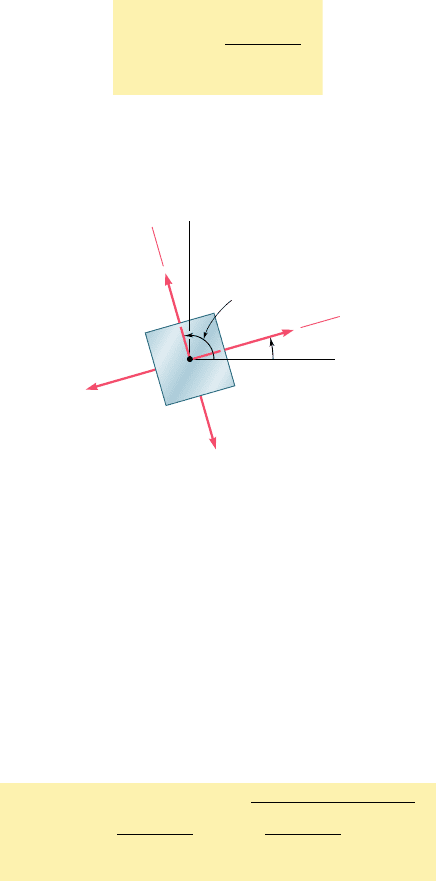
tan 2u
p
5
2t
xy
s
x
2 s
y
(7.12)
This equation defines two values 2u
p
that are 1808 apart, and thus
two values u
p
that are 908 apart. Either of these values can be used
to determine the orientation of the corresponding element (Fig. 7.9).
†This relation can also be obtained by differentiating s
x9
in Eq. (7.5) and setting the
derivative equal to zero: ds
x9
ydu 5 0.
min
min
max
max
p
p
y
Q
x
y'
x
'
Fig. 7.9 Principal stresses.
The planes containing the faces of the element obtained in this way
are called the principal planes of stress at point Q, and the corre-
sponding values s
max
and s
min
of the normal stress exerted on these
planes are called the principal stresses at Q. Since the two values u
p
defined by Eq. (7.12) were obtained by setting t
x9y9
5 0 in Eq. (7.6),
it is clear that no shearing stress is exerted on the principal planes.
We observe from Fig. 7.7 that
s
max
5 s
ave
1 Rands
m
i
n
5 s
ave
2 R (7.13)
Substituting for s
ave
and R from Eq. (7.10), we write
s
max, min
5
s
x
1 s
y
2
6
B
a
s
x
2 s
y
2
b
2
1 t
xy
2
(7.14)
Unless it is possible to tell by inspection which of the two principal
planes is subjected to s
max
and which is subjected to s
min
, it is neces-
sary to substitute one of the values u
p
into Eq. (7.5) in order to
determine which of the two corresponds to the maximum value of
the normal stress.
Referring again to the circle of Fig. 7.7, we note that the points
D and E located on the vertical diameter of the circle correspond to
bee80288_ch07_436-511.indd Page 444 10/30/10 1:37:19 AM user-f499bee80288_ch07_436-511.indd Page 444 10/30/10 1:37:19 AM user-f499 /Users/user-f499/Desktop/Temp Work/Don't Delete Job/MHDQ251:Beer:201/ch07/Users/user-f499/Desktop/Temp Work/Don't Delete Job/MHDQ251:Beer:201/ch07
Apago PDF Enhancer
445
the largest numerical value of the shearing stress t
x9y9
. Since the abscissa
of points D and E is s
ave
5 (s
x
1 s
y
)y2, the values u
s
of the param-
eter u corresponding to these points are obtained by setting s
x9
5
(s
x
1 s
y
)y2 in Eq. (7.5). It follows that the sum of the last two terms
in that equation must be zero. Thus, for u 5 u
s
, we write†
s
x
2 s
y
2
cos 2u
s
1 t
xy
sin 2u
s
5 0
or
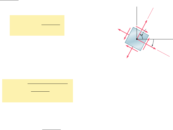
tan 2u
s
52
s
x
2 s
y
2t
xy
(7.15)
This equation defines two values 2u
s
that are 1808 apart, and thus
two values u
s
that are 908 apart. Either of these values can be used
to determine the orientation of the element corresponding to the
maximum shearing stress (Fig. 7.10). Observing from Fig. 7.7 that
the maximum value of the shearing stress is equal to the radius R of
the circle, and recalling the second of Eqs. (7.10), we write
t
max
5
B
a
s
x
2 s
y
2
b
2
1 t
xy
2
(7.16)
As observed earlier, the normal stress corresponding to the condition
of maximum shearing stress is
s¿ 5 s
ave
5
s
x
1 s
y
2
(7.17)
Comparing Eqs. (7.12) and (7.15), we note that tan 2u
s
is
the negative reciprocal of tan 2u
p
. This means that the angles 2u
s
and 2u
p
are 908 apart and, therefore, that the angles u
s
and u
p
are 458 apart. We thus conclude that the planes of maximum shear-
ing stress are at 458 to the principal planes. This confirms the
results obtained earlier in Sec. 1.12 in the case of a centric axial
loading (Fig. 1.38) and in Sec. 3.4 in the case of a torsional loading
(Fig. 3.19.)
We should be aware that our analysis of the transformation of
plane stress has been limited to rotations in the plane of stress. If
the cubic element of Fig. 7.5 is rotated about an axis other than the
z axis, its faces may be subjected to shearing stresses larger than the
stress defined by Eq. (7.16). As you will see in Sec. 7.5, this occurs
when the principal stresses defined by Eq. (7.14) have the same sign,
i.e., when they are either both tensile or both compressive. In such
cases, the value given by Eq. (7.16) is referred to as the maximum
in-plane shearing stress.
†This relation may also be obtained by differentiating t
x9y9
in Eq. (7.6) and setting the
derivative equal to zero: dt
x9y9
ydu 5 0.
max
max
s
s
y
Q
x
x'
y'
'
'
'
'
Fig. 7.10 Maximum shearing
stress.
7.3 Principal Stresses; Maximum
Shearing Stress
bee80288_ch07_436-511.indd Page 445 11/17/10 11:10:26 PM user-f499bee80288_ch07_436-511.indd Page 445 11/17/10 11:10:26 PM user-f499 /Users/user-f499/Desktop/Temp Work/Don't Delete Job/MHDQ251:Beer:201/ch07/Users/user-f499/Desktop/Temp Work/Don't Delete Job/MHDQ251:Beer:201/ch07
Apago PDF Enhancer
446
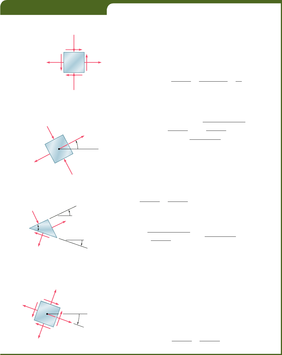
For the state of plane stress shown in Fig. 7.11, determine (a) the prin-
cipal planes, (b) the principal stresses, (c) the maximum shearing stress
and the corresponding normal stress.
(a) Principal Planes. Following the usual sign convention, we
write the stress components as
s
x
5150 MPas
y
5210 MPat
xy
5140 MPa
Substituting into Eq. (7.12), we have
tan 2u
p
5
2t
xy
s
x
2 s
y
5
21140
2
50 2 12102
5
8
0
60
2 u
p
5 53.1°and180° 1 53.1° 5 233.1°
u
p
5 26.6°and116.6°
(b) Principal Stresses. Formula (7.14) yields
s
max, min
5
s
x
1 s
y
2
6
B
a
s
x
2 s
y
2
b
2
1 t
xy
2
5 20 6 21302
2
1 1402
2
s
m
a
x
5 20 1 50 5 70 MPa
s
min
5 20 2 50 5230 MPa
The principal planes and principal stresses are sketched in Fig. 7.12. Mak-
ing u 5 26.68 in Eq. (7.5), we check that the normal stress exerted on
face BC of the element is the maximum stress:
s
x¿
5
50 2 1
0
2
1
50 1 10
2
cos 53.1° 1 40 sin 53.1°
5 20 1 30 cos 53.1° 1 40 sin 53.1° 5 70 MPa 5 s
max
(c) Maximum Shearing Stress. Formula (7.16) yields
t
max
5
B
a
s
x
2 s
y
2
b
2
1 t
xy
2
5 21302
2
1 1402
2
5 50 MPa
Since s
max
and s
min
have opposite signs, the value obtained for t
max
actually represents the maximum value of the shearing stress at the point
considered. The orientation of the planes of maximum shearing stress and
the sense of the shearing stresses are best determined by passing a section
along the diagonal plane AC of the element of Fig. 7.12. Since the faces
AB and BC of the element are contained in the principal planes, the
diagonal plane AC must be one of the planes of maximum shearing stress
(Fig. 7.13). Furthermore, the equilibrium conditions for the prismatic
element ABC require that the shearing stress exerted on AC be directed
as shown. The cubic element corresponding to the maximum shearing
stress is shown in Fig. 7.14. The normal stress on each of the four faces
of the element is given by Eq. (7.17):
s¿ 5 s
ave
5
s
x
1 s
y
2
5
50 2 10
2
5 20 MPa
EXAMPLE 7.01
10 MPa
40 MPa
50 MP
a
Fig. 7.11
min
30 MPa
max
70 MP
a
p
x
26.6
A
B
C
Fig. 7.12
min
max
'
max
p
26.6
s
p
45
45
18.4
A
C
B
Fig. 7.13
'
max
x
p
18.4
20 MPa
'
20 MPa
50 MPa
Fig. 7.14
bee80288_ch07_436-511.indd Page 446 10/30/10 1:37:25 AM user-f499bee80288_ch07_436-511.indd Page 446 10/30/10 1:37:25 AM user-f499 /Users/user-f499/Desktop/Temp Work/Don't Delete Job/MHDQ251:Beer:201/ch07/Users/user-f499/Desktop/Temp Work/Don't Delete Job/MHDQ251:Beer:201/ch07
