Barber J.R. Intermediate Mechanics of Materials
Подождите немного. Документ загружается.

5.4 Pure bending about an axis of symmetry 245
Some simplification follows from the fact that the stress is uniform in each plastic
region, permitting the stress distribution there to be replaced by a force resultant
through the local centroid. Figure 5.6 shows (a) a representative symmetric section
and (b) the corresponding stress distribution when the beam is loaded into the plastic
r´egime.
If the beam is bent to a radius R, the dimension d is given by equation (5.15).
The resultant bending moment can be written symbolically in the form
M = M
1
+ M
2
+ M
3
≡
ZZ
A
1
σ
zz
ydA +
ZZ
A
2
σ
zz
ydA +
ZZ
A
3
σ
zz
ydA , (5.19)
where A
1
,A
2
,A
3
are the areas of the two plastic regions and the elastic region respec-
tively, as shown in Figure 5.6 (a).
M
x
y
O
A
1
A
2
A
3
O
d
-d
Y
S
-
Y
S
zz
σ
y
(a) (b)
Figure 5.6: Bending about an axis of symmetry: (a) elastic and plastic zones, (b) the
corresponding stress distribution
In A
1
, the stress is uniform and equal to S
Y
, so
M
1
= S
Y
ZZ
A
1
ydA = S
Y
A
1
¯y
1
, (5.20)
where ¯y
1
is the coordinate of the centroid of A
1
. Similarly, in A
2
,
σ
zz
=−S
Y
, leading
to
M
2
= −S
Y
A
2
¯y
2
, (5.21)
but since the beam is symmetrical and loaded symmetrically, ¯y
1
= −¯y
2
, and hence
M
1
=M
2
and M
1
+ M
2
=2M
1
.
246 5 Non-linear and Elastic-Plastic Bending
These results have a simple physical explanation. The stress is uniform over A
1
and hence the resultant is a force of magnitude S
Y
A
1
acting through the centroid of
A
1
. As in §4.3.1, the value of A
1
¯y
1
for composite areas can conveniently be written
as the sum of similar results for the component areas.
Turning now to the elastic region A
3
, the expression for M
3
[the third integral in
equation (5.19)] is exactly the same as the moment transmitted by an elastic beam of
cross section A
3
bent to a radius R — i.e.
M
3
=
EI
3
R
, (5.22)
where I
3
is the second moment of area of the ‘embedded elastic beam’ of cross
section A
3
. Thus, the total moment can be written
M =
EI
3
R
+ 2S
Y
A
1
¯y
1
(5.23)
= S
Y
I
3
d
+ 2A
1
¯y
1
, (5.24)
using (5.15), where we recall that d is the distance from the neutral axis to the start
of the plastic region.
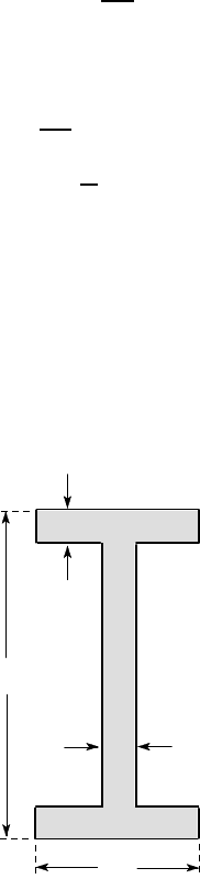
Example 5. 2
The I-beam of Figure 5.7 is loaded by a monotonically increasing bending moment
M. Find the relation between M and the radius of curvature R if the material is
elastic-perfectly plastic with Young’s modulus E =210 GPa and yield stress S
Y
=400
MPa.
20
200
100
20
all dimensions in mm
Figure 5.7
5.4 Pure bending about an axis of symmetry 247
For low values of M, the beam will be entirely elastic and the relation between
M and R is given by the elementary equation
M =
EI
R
,
where I is the second moment of area for the entire section, which we determine
below.
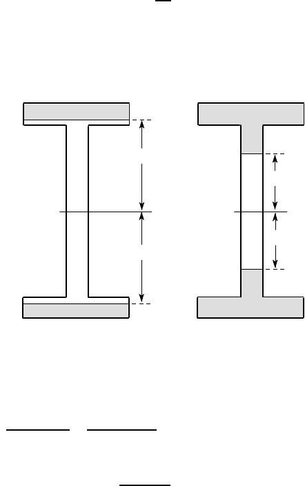
After plastic deformation begins, we can distinguish the two qualitatively differ-
ent states shown in Figures 5.8 (a,b).
P
E
P
d
d
P
E
d
d
P
(a) (b)
Figure 5.8
For case (a), the second moment of area I
3
for the embedded elastic beam is
I
3
=
(2d)
3
×0.1
12
−
0.16
3
×0.08
12
= 0.0667d
3
−27.3 ×10
−6
m
4
and
A
1
¯y
1
= 0.1 ×(0.1 −d) ×
(0.1 + d)
2
= 0.5 ×10
−3
−0.05d
2
m
3
.
The value of I for the full section, which we need to describe the solution in the
elastic range, is obtained by setting d = 0.1 m in the expression for I
3
above — i.e.
I = 0.0667 ×(0.1)
3
−27.3 ×10
−6
= 39.4 ×10
−6
m
4
.
Substituting for I
3
, A
1
¯y
1
in (5.24), we have
M = S
Y
(0.0667d
2
−27.3 ×10
−6
d
−1
+ 10
−3
−0.1d
2
)
= 400 ×10
6
(10
−3
−0.0333d
2
−27.3 ×10
−6
d
−1
) Nm.
In particular, first yield corresponds to the value d =0.1 and hence

248 5 Non-linear and Elastic-Plastic Bending
M
Y
= 157,600 Nm = 157.6 kNm.
The relation between M and R is obtained by substituting
d =
S
Y
R
E
= 1.90 ×10
−3
R
and hence
M = 400 ×10
6
(10
−3
−0.121 ×10
−6
R
2
−14.33 ×10
−3
R
−1
) Nm.
We also note that the radius of curvature at first yield is
R
Y
=
0.1E
S
Y
= 52.5 m,
from (5.15).
Case (a) applies as long as 0.08 < d < 0.1 and hence the transition to case (b)
occurs when
M = 400 ×10
6
(10
−3
−0.0333 ×0.08
2
−27.3 ×10
−6
0.08
−1
) = 178100 Nm.
For case (b),
I
3
=
(2d)
3
×0.02
12
= 0.01333d
3
m
4
and
A
1
¯y
1
= 0.1 ×0.02 ×0.09 + (0.08 −d) ×0.02 ×
(0.08 + d)
2
= 0.244 ×10
−3
−0.01d
2
m
3
,
where we have treated the flange and the section of web above y=d as two separate
areas for this computation.
Thus, using equation (5.24),
M = S
Y
(0.01333d
2
+ 0.488 ×10
−3
−0.02d
2
= 400 ×10
6
(0.488 ×10
−3
−6.67 ×10
−3
d
2
) Nm
= 400 ×10
6
(0.488 ×10
−3
−24 ×10
−9
R
2
) Nm.
The maximum bending moment M
P
occurs when d = 0,R = 0 and the section is
fully plastic. We therefore have
M
P
= 400 ×10
6
×0.488 ×10
−3
= 195,200 Nm = 195.2 kNm.
The relation between M and R is illustrated in Figure 5.9.
5.4 Pure bending about an axis of symmetry 249
M
0
0.0190
0.0238
195.2
178.1
157.6
P
M
Y
M
kNm
R
1
(a)
(b)
(m )
-1
elastic
Figure 5.9
5.4.2 Fully plastic moment and shape factor
In the above example, Figure 5.9 shows that the curvature increases rapidly once we
exceed the moment M
Y
for first yield and in fact the fully plastic moment M
P
is not
very much larger than M
Y
. We define the shape factor
f =
M
P
M
Y
(5.25)
and for the I-beam of the example we have f =195.2/157.6=1.239. In other words, a
24% increase in moment beyond first yield is sufficient to cause the beam to collapse
completely. I-beams in general have relatively low values of shape factor because
the flanges are responsible for the greater part of the moment transmitted in bending
and the flange stresses are nowhere much below the yield stress when the outermost
fibres yield.
From a design point of view, it is often sufficient to determine just M
Y
and M
P
,
since these define respectively the moment above which some permanent damage
can be expected and the moment for total collapse of the beam. For the fully plastic
case, equation (5.24) reduces to
M
P
= 2S
Y
A ¯y , (5.26)
where A is the area above the axis of symmetry and ¯y is the coordinate of its centroid.
Example 5. 3
Determine M
Y
,M
P
and the shape factor f for a solid circular section of diameter d,
if the uniaxial yield stress for the material is S
Y
.
First yield will occur when the stress at y=d/2 is equal to S
Y
, so
M
Y
I
=
2S
Y
d
,
250 5 Non-linear and Elastic-Plastic Bending
giving
M
Y
=
2S
Y
d
π
d
4
64
=
π
S
Y
d
3
32
,
where we have used the result that I =
π
d
4
/64 for a circular cross section of diameter
d.
For the fully plastic case, we have
A ¯y =
ZZ
ydA =
Z
π
0
Z
d/2
0
r sin
θ
rdrd
θ
=
2
3
d
2
3
,
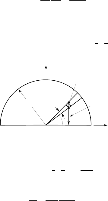
for the area above the axis of symmetry, using the integration scheme of Figure 5.10.
x
y
dA = r dr dθ
y = r sin θ
θ
d
2
O
dθ
Figure 5.10
It then follows that
M
P
= 2S
Y
×
2
3
d
2
3
=
S
Y
d
3
6
and the shape factor is
f =
M
P
M
Y
=
S
Y
d
3
6
32
π
S
Y
d
3
= 1.70 .
Notice that the shape factor is larger for the circle than for the I-beam, because the
greater volume of material nearer to the axis of symmetry contributes significantly
to the transmitted moment.
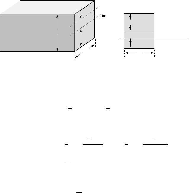
5.5 Bending of a symmetric section about an orthogonal axis
Figure 5.11 shows a beam section which is symmetric about the y-axis, but which is
bent about the x-axis.
Suppose that the neutral axis is parallel to the x-axis, so that the strain and hence
the stress is a function of y only. It then follows from the third of equations (5.16)
that M
y
= 0, since symmetric elements with equal and opposite values of x cancel
each other in the integral. We therefore deduce that the neutral axis will be parallel
to the bending axis, when this is orthogonal to an axis of symmetry for the section.
5.5 Bending of a symmetric section about an orthogonal axis 251
O
M
x
y
Figure 5.11: Symmetric section bent about an orthogonal axis
This argument is not subject to the other restrictions listed in §5.4 — in particular,
it applies if there is an axial force and also if the monotonic stress-strain relation is
different in tension and compression. However, the neutral axis will not generally
pass through the centroid of the section and it will move (whilst remaining parallel
to the bending axis) as the loading increases.
5.5.1 The fully plastic case
The simplest case is that of full plasticity, where every point in the section has yielded
and is either at S
Y
or −S
Y
as shown in Figure 5.12.
M
A
1
A
2
-
Y
S
Y
S
+
Figure 5.12: Fully plastic state for bending of a symmetric section about an orthog-
onal axis
The axial force is then
F =
ZZ
A
σ
zz
dA =
ZZ
A
1
S
Y
dA +
ZZ
A
2
(−S
Y
)dA = (A
1
−A
2
)S
Y
, (5.27)
where A
1
,A
2
are the areas above and below the neutral axis respectively. If there is
no axial force, F =0 and A
1
= A
2
. In other words, the neutral axis for full plasticity
252 5 Non-linear and Elastic-Plastic Bending
divides the section into two equal areas. For sections that are not symmetric about the
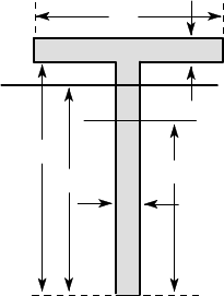
x-axis, this ‘median line’ does not generally pass through the centroid. For example,
the centroid of the T-section of Figure 5.13 is 74.4 mm from the bottom, whereas
the median line is 90 mm from the bottom. Thus, if we apply a gradually increasing
bending moment M to the T-section beam, the neutral axis will initially pass through
the centroid, but it will migrate upwards after yielding starts, tending towards the
median line as the fully plastic moment M
P
is approached.
10
80
100
median
10
centroidal axis
90
74.4
all dimensions in mm
Figure 5.13: Centroidal and median axes for a T-section
Once the neutral axis has been found, the fully plastic moment is determined as
M
P
=
ZZ
A
1
S
Y
ydA +
ZZ
A
2
(−S
Y
)ydA = S
Y
(A
1
¯y
1
−A
2
¯y
2
) , (5.28)
where ¯y
1
, ¯y
2
define the centroids of the areas A
1
,A
2
. Since there is no axial force, any
convenient origin may be used to define the coordinates ¯y
1
, ¯y
2
.
Example 5. 4
Find the fully plastic moment for the U-section of Figure 5.14, if the material yields
at a stress S
Y
=300 MPa.
The total area of the section is
A = 100 ×100 −80 ×60 = 5200 mm
2
,
so the area above the median line must be A/2 = 2600 mm
2
. The neutral axis is
therefore 65 mm from the top of the section (since 65 ×40 = 2600) as shown in
Figure 5.15.
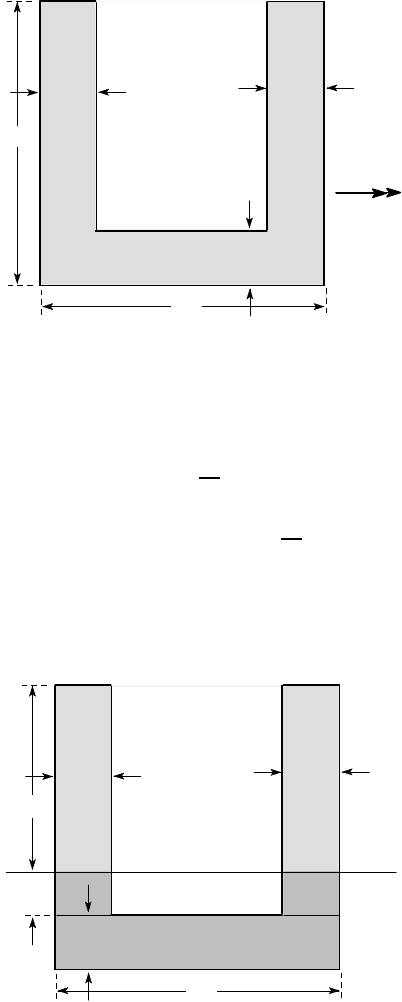
5.5 Bending of a symmetric section about an orthogonal axis 253
M
20
20
20
100
100
all dimensions in mm
Figure 5.14
We therefore have
A
1
¯y
1
= 65 ×40 ×
65
2
= 84,500 mm
3
A
2
¯y
2
= 20 ×100 ×(−25) + 15 ×40 ×
−
15
2
= −54,500 mm
3
and
M
P
= 300 ×10
6
(84500 + 54500) ×10
−9
= 41,700 Nm,
from equation (5.28).
20
20
100
15
65
neutral axis
A
1
A
1
A
2
20
all dimensions in mm
Figure 5.15
254 5 Non-linear and Elastic-Plastic Bending
5.5.2 Non-zero axial force
The method is only slightly modified if the axial force is non-zero. Equation (5.27)
again provides a condition for determining the location of the neutral axis after which
the fully plastic moment is given by (5.28). Notice however that if there is an axial
force, the resultant moment will depend on the axis about which it is computed. An
alternative description of the loading in such cases is to specify the resultant axial
force and its line of action.
Example 5. 5
A rectangular beam of width a and depth b is loaded by an axial tensile force F
whose line of action is displaced a distance d from the axis of symmetry, as shown
in Figue 5.16. Find the collapse load F
P
and the dimension c defining the location of
the neutral axis and sketch their variation with d.
d
F
a
b
b / 2
a
neutral axis
c
b / 2
(a) (b)
Figure 5.16
At collapse, the section above the neutral axis has yielded in tension and that
below in compression, so the axial force is obtained from (5.27) as
F
P
= S
Y
a
b
2
+ c
−S
Y
a
b
2
−c
= 2S
Y
ac .
The moment about the axis of symmetry is
M = F
P
d = S
Y
a
b
2
+ c
b
2
−c
2
−S
Y
a
b
2
−c
−
b
2
−c
2
= S
Y
a
b
2
4
−c
2
.
Substituting for F
P
and cancelling a factor S
Y
, we have
b
2
4
−c
2
= 2cd ,
with solution