Balakumar Balachandran, Magrab E.B. Vibrations
Подождите немного. Документ загружается.

From the contour curves shown in Figure 9.13b, we see that, as in the
case of a cantilever beam, certain natural frequencies can be obtained from a
range of combinations of the values of K
s
and h
1
. We also note that as the
spring is placed closer to the center of the beam, the magnitude of K
s
that is
required to maintain a constant frequency decreases.
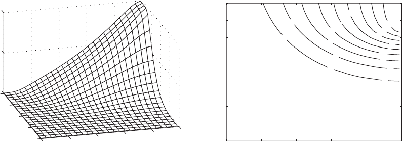
For the last case, we consider a beam clamped at both ends. For this case,
we substitute Eq. (9.122) into Eq. (9.148) and use the resulting expression
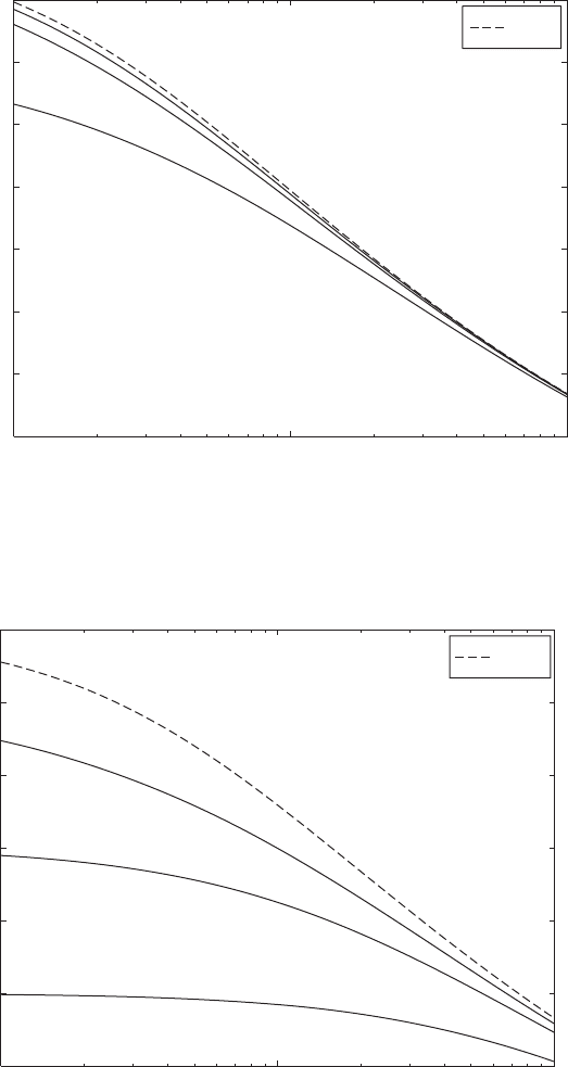
to obtain the surface shown in Figure 9.14. In Figure 9.14a, we see that the
lowest natural-frequency coefficient reaches a peak of when
K
s
2500 (i.e., when log
10
(K
s
) 3.4) and h
1
0.5. From Case 1 of Table 9.3,
we see that a clamped-clamped beam without attachments has a second natu-
ral frequency of
1
/p 2.4998 with a node point at h 0.500. Therefore, by
placing a stiff spring at or near the node point of this second natural frequency,
one effectively creates a system whose lowest natural frequency is now equal
to that of the second natural frequency of a beam without attachments. This is
accomplished because the beam is forced to assume the mode shape associ-
ated with the second natural frequency of the beam without attachments.
From the contour curves shown in Figure 9.14b, we see that, as in the
case for a cantilever beam, certain natural frequencies can be obtained from a
range of combinations of the values of K
s
and h
1
. We also note that as the
spring is placed closer to the center of the beam, the magnitude of K
s
that is
required to maintain a constant frequency decreases.
Figures 9.12 to 9.14 clearly show the trends of the natural-frequency co-
efficients. However, since numerical values are somewhat difficult to obtain
from these figures, we have also presented in Table 9.6 the lowest natural-
frequency coefficients for many different combinations of boundary condi-
tions and in-span locations.
1
/p 2.5
600 CHAPTER 9 Vibrations of Beams
0
0.1
0.2
0.3
0.4
(a) (b)
0.5
0
1
2
3
4
1.5
2
2.5
Ω
1
/
log
10
(K
s
)
1
1.6
1.6
1.6
1.7
1.7
1.7
1.8
1.8
1.9
1.9
2
2
2.1
2.1
2.2
2.3
2.4
0 0.1 0.2 0.3 0.4 0.5
0
0.5
1
1.5
2
2.5
3
3.5
4
log
10
(K
s
)
1
FIGURE 9.14
(a) Variation of the lowest natural-frequency coefficient of a clamped-clamped beam restrained by a spring K
s
attached at h
1
and
(b) contour curves of constant values of the lowest natural-frequency coefficient of surface in (a). Note: Since the boundary conditions
are symmetric, we only need to consider the region 0 h
1
0.5.

Beams with in-span mass M
s
We start with a cantilever beam. For this case,
we substitute Eq. (9.120) into Eq. (9.152) and use the resulting expression to
obtain the surface shown in Figure 9.15. In Figure 9.15a, we see that the effect
of the mass is to lower the first natural frequency, which reaches its minimum
value at h
1
1.0, the free end of the beam, irrespective of the value of M
s
.
From the contour curves shown in Figure 9.15b, we see that as with the beam
restrained with an in-span spring, certain natural frequencies can be obtained
from a range of combinations of the values of M
s
and h
1
.
We now consider a beam hinged at both ends. For this case, we substitute
Eq. (9.120) in Eq. (9.144) and use the resulting expression to obtain the
9.3 Free Oscillations 601
FIGURE 9.15
(a) Variation of the lowest natural-frequency coefficient of a cantilever beam with a mass M
s
attached at h
1
and
(b) contour curves of constant values of the lowest natural-frequency coefficient of surface in (a).
1
/P
Hinged-Hinged Clamped-Clamped Clamped-Free
K
s
↓ H
1
→ 0.3 0.4 0.5 0.3 0.4 0.5 0.5 0.75 1.0
0 1.0000 1.0000 1.0000 1.5056 1.5056 1.5056 0.5969 0.5969 0.5969
10 1.0316 1.0432 1.0477 1.5145 1.5212 1.5242 0.6442 0.7422 0.8400
50 1.1296 1.1737 1.1908 1.5473 1.5782 1.5919 0.7515 0.9964 1.0825
100 1.2143 1.2856 1.3151 1.5830 1.6393 1.6649 0.8177 1.1552 1.1588
500 1.4645 1.6374 1.7687 1.7519 1.9247 2.0298 0.9423 1.4560 1.2315
1000 1.5411 1.7440 1.9960 1.8412 2.0724 2.2736 0.9691 1.4699 1.2407
TABLE 9.6
Lowest Natural-Frequency Coefficients for a Beam with an In-Span Spring for Many Different Combinations of Boundary Conditions
and In-Span Locations.
(b)
0.15
0.2
0.2
0.25
0.25
0.3
0.3
0.3
0.35
0.35
0.35
0.4
0.4
0.4
0.45
0.45
0.45
0.5
0.5
0.5
0.5
0.55
0.55
0.55
0.55
0 0.2 0.4 0.6 0.8 1
1
0.5
0
0.5
1
1.5
2
log
10
(M
so
)
1
0
0.2
0.4
(a)
0.6
0.8
1
1
0
1
2
0.1
0.2
0.3
0.4
0.5
0.6
log
10
(M
so
)
1
Ω
1
/
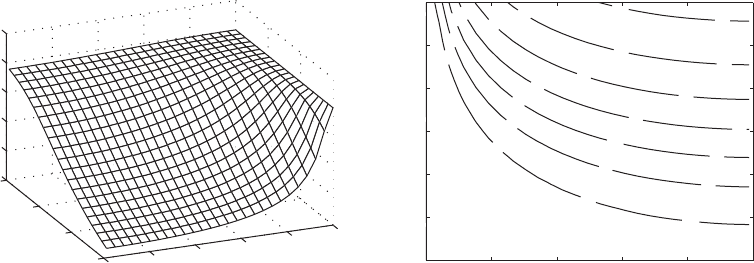
surface shown in Figure 9.16. In Figure 9.16a, we again see that the effect of
the mass is to lower the first natural frequency, which reaches its minimum
value at h
1
0.500, the center of the beam for all values of M
s
. From the con-
tour curves shown in Figure 9.16b, we see that as with the beam restrained
with an in-span spring, certain natural frequencies can be obtained from a
range of combinations of the values of M
s
and h
1
.
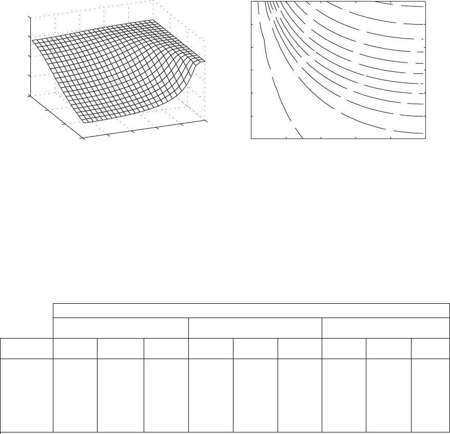
For the last case, we consider a beam clamped at both ends. For this case,
we substitute Eq. (9.120) into Eq. (9.148) and use the resulting expression to
obtain the surface shown in Figure 9.17. The variations of the first natural co-
efficient for this system are similar to those obtained for the cantilever beam
and the beam hinged at both ends.
Figures 9.15 to 9.17 clearly show the trends of the natural-frequency co-
efficients. However, since numerical values are somewhat difficult to obtain
from these figures we have also presented in Table 9.7 the lowest natural-
frequency coefficients for many different combinations of the boundary con-
ditions and in-span locations.
Beams with an in-span single degree-of-freedom system When a single
degree-of-freedom system is attached to a beam, its interactions with the
beam are far more complex than when just a mass or just a spring is attached.
It will be shown that the single degree-of-freedom system introduces an ad-
ditional natural frequency and greatly influences one of the beam’s modes
depending on what the natural frequency of the single degree-of-freedom sys-
tem is prior to its attachment; that is, depending on the value of
s
. We shall
illustrate what these complex interactions are by considering a cantilever
beam with a single degree-of-freedom system attached at its free end h 1.
602 CHAPTER 9 Vibrations of Beams
0
(b)
0.3
0.3
0.4
0.4
0.4
0.5
0.5
0.5
0.6
0.6
0.6
0.6
0.7
0.7
0.7
0.7
0.8
0.8
0.8
0.8
0.9
0.9
0.9
0.9
0 0.1 0.2 0.3 0.4 0.5
1
0.5
0
0.5
1
1.5
2
log
10
(M
so
)
1
0.1
0.2
0.3
0.4
(a)
0.5
1
0
1
2
0.2
0.4
0.6
0.8
1
1.2
log
10
(M
so
)
1
Ω
1
/
FIGURE 9.16
(a) Variation of the lowest natural-frequency coefficient of a hinged-hinged beam with a mass M
s
attached at h
1
and (b) contour
curves of constant values of the lowest natural-frequency coefficient of surface in (a). Note: Since the boundary conditions are
symmetric, we only need to consider the region 0 h
1
0.5.
We shall hold the mass M
s
constant and vary k
s
in order to change the value
of
s
. In this manner, we can compare the various systems with the case of a
beam carrying a mass M
s
at its free end. In addition, we also shall show that
in order to properly interpret the results, one must use Eq. (9.137) to obtain
the value of Z
o
/W
n
(h
1
) for each
n
. To this end, we substitute Eq. (9.118) in
Eq. (9.120), select M
so
0.1, and set h
1
1 to obtain the results presented in
Table 9.8.
In Table 9.8, we have examined four different cases with the following
values of K
s
: 0.5, 5, 50, and 500. A fifth case, in which , is theK
s
q
9.3 Free Oscillations 603
FIGURE 9.17
(a) Variation of the lowest natural-frequency coefficient of a clamped-clamped beam with a mass M
s
attached at h
1
and (b) contour
curves of constant values of the lowest natural-frequency coefficient of surface in (a). Note: Since the boundary conditions are
symmetric, we only need to consider the region 0 h
1
0.5.
(b)
0.4
0.5
0.5
0.6
0.6
0.6
0.7
0.7
0.7
0.8
0.8
0.8
0.9
0.9
0.9
1
1
1
1
1.1
1.1
1.1
1.1
1.2
1.2
1.2
1.2
1.3
1.3
1.3
1.3
1.4
1.4
1.4
1.4
1.5
1.5
1.5
0 0.1 0.2 0.3 0.4 0.5
1
0.5
0
0.5
1
1.5
2
log
10
(M
so
)
1
0
0.1
0.2
(a)
0.3
0.4
0.5
1
0
1
2
0
0.5
1
1.5
2
log
10
(M
so
)
1
Ω
1
/
1
/P
Hinged-Hinged Clamped-Clamped Clamped-Free
M
so
↓ H
1
→ 0.3 0.4 0.5 0.3 0.4 0.5 0.5 0.75 1.0
0.0 1.0000 1.0000 1.0000 1.5056 1.5056 1.5056 0.5969 0.5969 0.5969
0.1 0.9694 0.9591 0.9553 1.4621 1.4339 1.4228 0.5901 0.5735 0.5484
0.5 0.8783 0.8496 0.8401 1.3234 1.2490 1.2246 0.5661 0.5106 0.4520
1.0 0.8049 0.7697 0.7586 1.2080 1.1211 1.0943 0.5412 0.4641 0.3972
5.0 0.5930 0.5579 0.5474 0.8806 0.8013 0.7783 0.4364 0.3383 0.2769
10 0.5061 0.4748 0.4656 0.7497 0.6803 0.6603 0.3804 0.2883 0.2342
TABLE 9.7
Lowest Natural-Frequency Coefficients for a Beam with a Mass for Many Different Combinations of Boundary Conditions
and In-Span Locations.
case of a cantilever beam with a mass attached at its free end [see Eq. (9.120)],
and this case is used as the reference case. We denote the natural-frequency co-
efficients of this system by
n,ref
. In order to identify the natural-frequency co-
efficient and mode shape associated with the single degree-of-freedom system,
we need two pieces of information: the value of Z
o
/W
n
(h
1
) and the value of
s
.
We use this information as follows. The largest value of for a0Z
o
/W
n
1h
1
20
604 CHAPTER 9 Vibrations of Beams
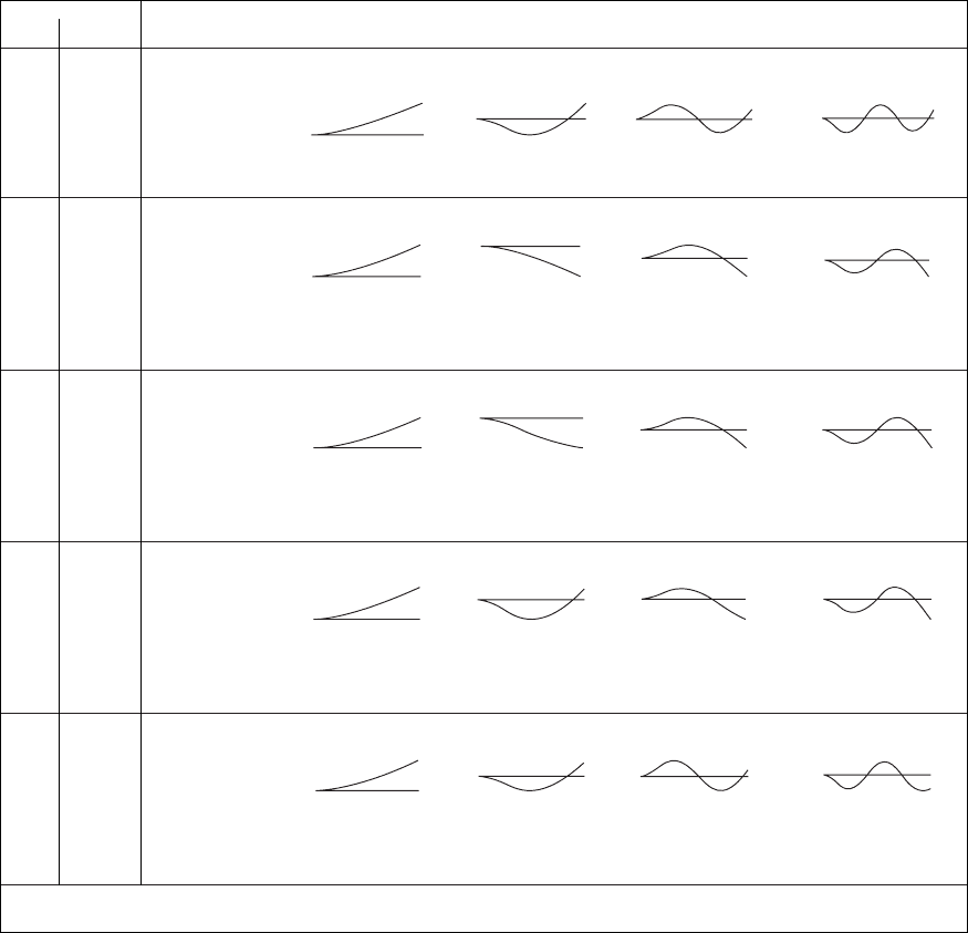
TABLE 9.8
Natural-Frequency Coefficients, Mode Shapes and Node Points for a Cantilever Beam with a Single Degree-of-Freedom System Attached at h
1
1
with M
so
0.1.
K
s
s
/P n 1 n 2 n 3 n 4
n
p 0.5484 1.4004 2.3717 3.3492
Mode
q —
shapes
Node None 0.841 0.530, 0.921 0.375, 0.673, 0.953
points
*
n
p 0.4507 0.6297 1.4957 2.5006
Mode
0.5 0.4760
shapes
Node None None 0.783 0.503, 0.868
points
*
Z
o
/W
n
(h
1
) 5.089 0.485 0.010 0.0013
n
p 0.54071 0.9218 1.5116 2.5036
Mode
5 0.8464
shapes
Node None None 0.775 0.503, 0.867
points
*
Z
o
/W
n
(h
1
) 1.200 2.459 0.109 0.013
n
p 0.54766 1.3405 1.7884 2.5403
Mode
50 1.5052
shapes
Node None 0.890 0.673 0.496, 0.854
points
*
Z
o
/W
n
(h
1
) 1.018 2.696 1.007 0.1406
n
p 0.5483 1.3959 2.3219 3.0735
Mode
500 2.6767
shapes
Node None 0.844 0.541, 0.948 0.408, 0.728
points
*
Z
o
/W
n
(h
1
) 1.002 1.080 2.305 3.0735
*
Values of h not including the boundaries.
given K
s
and
s
indicates that this is the frequency and mode shape that is as-
sociated with the single degree-of-freedom system. We denote this frequency
coefficient
n,sdof
. It is seen from the results in the table that the single degree-
of-freedom system always affects the mode that is associated with the smallest
value of
n,ref
that is greater than
s
such that the resulting natural-frequency
values are ordered as
n,sdof
n,ref
n1
where
n1
is the natural-
frequency coefficient for the system with the single degree-of-freedom system
attached. For example, when K
s
5.0,
s
/p 0.8464, which is less
than
2,ref
/p 1.4004. We see that Z
o
/W
n
(h
1
) 2.495 is the maximum value,
which occurs at n 2; thus, (
2
/p 0.9218) (
2,ref
1.4004)
(
3
/0.1.5116). Thus, we see that the effect of the single degree-of-freedom
system is to “split” the affected
n,ref
into two modes, one whose natural fre-
quency is less than
n,ref
and one that is greater than
n,ref
.
We now discuss further the type of information that is contained in the
mode shape ratio Z
o
/W
n
(h
1
). A positive value of Z
o
/W
n
(h
1
) indicates that the
single degree-of-freedom mass M
s
is in phase with the beam displacement at
the point of attachment and a negative value of Z
o
/W
n
(h
1
) indicates that the
single degree-of-freedom mass M
s
is out of phase. This type of in phase and
out of phase motion is similar to that obtained for a two degree-of-freedom
system. However, when Z
o
/W
n
(h
1
) 1 the mass M
s
and the beam displace-
ment at h
1
are almost equal and the beam is behaving as if the mass were
attached directly to the beam. We see from the column labeled n 1 in
Table 9.8 that the natural-frequency coefficient is very closely equal to that of
a beam carrying a mass only. This also is seen in the column labeled n 2
for the case when K
s
500.
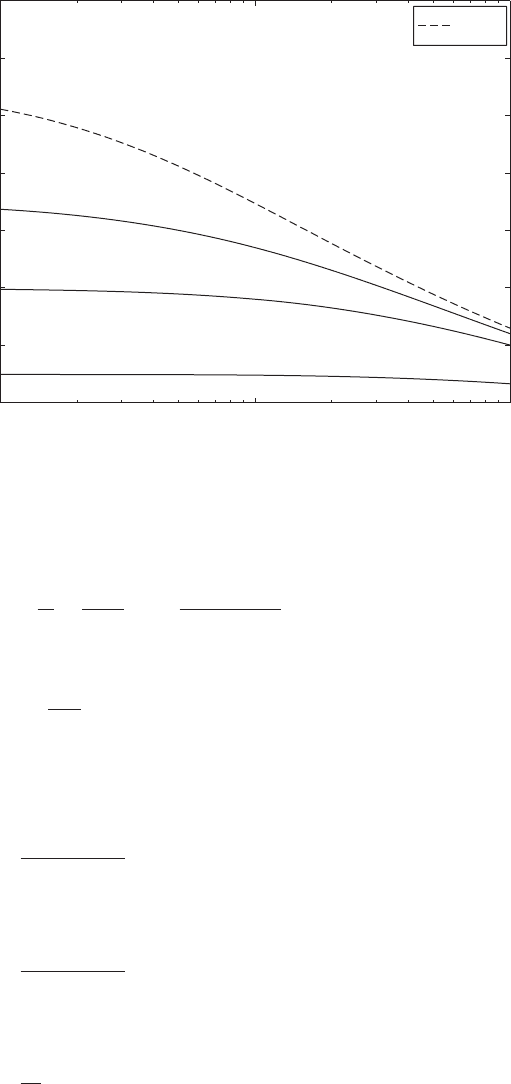
The variations of the lowest natural frequency of a beam with a single
degree-of-freedom system with respect to M
so
for many different values of
s
are given in Figure 9.18 for the hinged-hinged beam for h
1
0.5, in Figure
9.19 for clamped-clamped beam for h
1
0.5, and in Figure 9.20 for the
clamped-free beam for h
1
1.0. In each of these figures, we have plotted for
reference the variation of the lowest natural frequency of a beam with only a
mass M
so
attached. This natural-frequency coefficient is denoted These
reference curves are the same as those presented in Figures 9.15 to 9.17 at the
appropriate value of h
1
.
Comparison with two springs in series approximation As discussed in
Chapter 2, in many situations where an inertia element is attached to a beam,
the beam stiffness is taken into account to establish an equivalent single-
degree-of-freedom system. This situation is revisited in the context of the
beam system shown in Figure 9.11c to point out when it is reasonable to neg-
lect the beam inertia and when it is not. First, we consider the determination
of the natural frequency of an equivalent single degree-of-freedom system.
This is done by using the static stiffness values given for Cases 4, 5, and 6 of
Table 2.3 for the cantilever, pinned pinned and clamped-clamped beams, re-
spectively. In each case, the approximation obtained for the first natural fre-
quency of the system shown in Table 2.3 is compared to the natural frequency
obtained when the inertia of the beam is taken into account. We note from the
M
so
,1
.
9.3 Free Oscillations 605
10
1
10
0
10
1
0.2
0.25
0.3
0.35
0.4
0.45
0.5
0.55
M
so
Ω
s
/ 0.7
Ω
s
/ 0.5
Ω
s
/ 0.9
Ω
M
so
,1
Ω
1
/
FIGURE 9.18
Lowest natural-frequency coefficient for a cantilever beam carrying a single degree-of-
freedom system at its free end h
1
1 as a function of M
so
for several values of
s
.
FIGURE 9.19
Lowest natural-frequency coefficient for a hinged-hinged beam carrying a single degree-of-
freedom system at its midpoint h
1
0.5 as a function of M
so
for several values of
s
.
10
1
10
0
10
1
0.4
0.5
0.6
0.7
0.8
0.9
1
M
so
Ω
1
/
Ω
M
so
,1
Ω
s
/ 0.9
Ω
s
/ 0.7
Ω
s
/ 0.5
discussion on spring combinations in series shown in Figure 2.8a and from
Eq. (a) of Example 2.3 that the equivalent spring constant k
e
for a spring k
s
at-
tached to a beam of spring constant k
beam
is
(9.156)
From Table 2.3, we find that
(9.157)
where a is a function of the boundary conditions and is given as follows:
Clamped-clamped
(9.158a)
Hinged-hinged
(9.158b)
Clamped-free
(9.158c)a
3
h
3
1
a
3
h
2
1
11 h
1
2
2
a
3
h
3
1
11 h
1
2
3
k
beam
aEI
L
3
k
e
a
1
k
s
1
k
beam
b
1
k
s
1 k
s
/k
beam
9.3 Free Oscillations 607
FIGURE 9.20
Lowest natural-frequency coefficient
for a clamped-clamped beam carry-
ing a single degree-of-freedom
system at its midpoint h
1
0.5 as
a function of M
so
for several values
of
s
.
10
1
10
0
10
1
0.4
0.6
0.8
1
1.2
1.4
1.6
1.8
M
so
Ω
M
so
,1
Ω
1
/
Ω
s
/ 1.1
Ω
s
/ 0.8
Ω
s
/ 0.5

Then, from Eq. (9.156), we have
(9.159)
Thus, the natural frequency of the equivalent single degree-of-freedom sys-
tem obtained from the equivalent spring constant is given by
(9.160)
To determine the first natural frequency when the beam’s inertia is taken
into account, we use Eq. (9.115) and find that the first natural frequency is
given by
(9.161)
where
1
is the first nondimensional frequency coefficient obtained by solv-
ing the appropriate characteristic equation. The percentage error e between
the natural frequency for a single degree-of-freedom system and the first nat-
ural frequency of the beam system in Figure 9.11c is
29
(9.162)
When K
s
is very large, that is, when the mass is directly attached to the beam,
Eq. (9.162) simplifies to
(9.163)
Since a is a function of the beam boundary conditions and the location h
1
of
where the single degree-of-freedom system is attached, the percentage error
is also a function of these quantities in addition to K
s
and M
so
.
We have numerically evaluated Eqs. (9.162) and (9.163) to determine the
values of the mass M
o
and its location h
1
that are required for the error to be
equal to or less than a specific value for each of the following boundary con-
ditions: (i) clamped-clamped, (ii) hinged-hinged, and (iii) clamped-free. The
results obtained from Eq. (9.162) are shown in Figures 9.21 to 9.23 for e
2.5% and for e 5%. It is seen from these figures that the single degree-of-
freedom system interacts with the beam in a complex way and that in order to
approximate the system with two springs in series and stay within these error
e 100 a
1
2
1
B
a
M
so
1b
%
100 a
1
2
1
B
K
s
M
so
a
1
1 K
s
/a
b
1b
%
e 100 a
v
n
v
e
1b 100 a
1
2
1
B
m
o
k
s
L
3
EIM
s
a
1
1 K
s
/a
b
1b
v
e
2
1
B
EI
m
o
L
3
v
n
B
k
e
M
s
B
k
s
M
s
a
1
1 K
s
/a
b
k
e
k
s
1 k
s
L
3
/aEI
k
s
1 K
s
/a
608 CHAPTER 9 Vibrations of Beams
29
For another approach to this topic see: M. Gürgöze, “On the Representation of a Cantilever
Beam Carrying a Tip Mass by an Equivalent Spring-Mass System,” J. Sound Vibration, Vol. 282,
pp. 538–542 (2005).
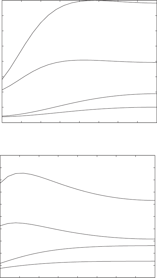
9.3 Free Oscillations 609
bounds, one must take into account both the location of the single degree-
of-freedom system on the beam and the beam’s boundary conditions. From
these figures, it is seen that for a given set of boundary conditions, single
degree-of-freedom system location and non dimensional stiffness, a larger
mass ratio will have less error.
FIGURE 9.21
Values of M
so
for a beam clamped
at each end and carrying a single
degree-of-freedom system at h
1
for
which the error is less than 5% and
less than 2.5% for two values of K
s
.
Note: Because the boundary condi-
tions are symmetric, we only need to
consider the region 0 h
1
0.5.
FIGURE 9.22
Values of M
so
for a beam hinged
at each end and carrying a single
degree-of-freedom system at h
1
for
which the error is less than 5% and
less than 2.5% for two values of K
s
.
Note: Because the boundary condi-
tions are symmetric, we only need to
consider the region 0 h
1
0.5.
0.1 0.15 0.2 0.25 0.3 0.35 0.4 0.45 0.5
0
0.5
1
1.5
2
2.5
3
3.5
4
K
s
500, 2.5%
K
s
500, 5%
K
s
100, 2.5%
K
s
100, 5%
M
so
1
0.1 0.15 0.2 0.25 0.3 0.35 0.4 0.45 0.5
0
1
2
3
4
5
6
7
8
9
10
M
so
K
s
200, 2.5%
K
s
200, 5%
K
s
50, 2.5%
K
s
50, 5%
1