Balakumar Balachandran, Magrab E.B. Vibrations
Подождите немного. Документ загружается.


solving for the different boundary conditions shown in Table 9.1 on a case-
by-case basis, a solution is obtained for a general set of boundary conditions.
Then, in Section 9.3.3, this general solution is appropriately modified for var-
ious special cases of the general boundary conditions.
In order to determine the solution by using the Laplace transform it is
recognized that Eq. (9.68) is a special case of Eq. (A.7) of Appendix A, with
the function W taking the place of y, the nondimensional spatial variable h
taking the place of the independent variable x and b k f (x) 0 in
Eq. (A.7). Denoting the Laplace transform of W(h) by —that is,
—and making use of Eqs. (A.8) and (A.9), we find that the Laplace transform
of Eq. (9.68) results in
(9.78)
where W(0), W(0), W(0), and W(0) are the displacement, slope, second de-
rivative of W(h), and third derivative of W(h), respectively, at h 0. These four
quantities and the nondimensional frequency coefficient represent the five
unknown quantities that need to be determined. Noting that we have the four
boundary conditions given by Eqs. (9.69), one can at best solve for four of these
quantities, one of which will be the nondimensional frequency coefficient. This
means that the resulting solution for the mode shape will have an arbitrary con-
stant. This situation is similar to what we encountered in Chapter 7, where we
found that an eigenvector is arbitrary with respect to a scaling constant.
We see from the boundary conditions given by Eqs. (9.69a) that W(0)
and W(0) are expressed in terms of W(0) and W(0), respectively. Thus, one
of the advantages of the Laplace transform solution method is that two of the
four unknowns are directly specified by the boundary conditions at h 0,
thereby leaving only three unknown quantities to be determined; in this case,
W(0), W(0), and . Making use of Laplace transform pairs 23 through 26 in
Table A of Appendix A, or alternatively, directly making use of Eqs. (A.16)
and (A.17) of Appendix A with d e , leads to the following inverse
Laplace transform of Eq. (9.78)
(9.79)
where the nondimensional spatial functions are given by
(9.80)T1j2 0.53sinh1
j2 sin1j24
S1j 2 0.53cosh1j 2 cos1j24
R1j 2 0.53sinh1j2 sin1j 24
Q1j 2 0.53cosh1j 2 cos1j24
W–102S1h 2/
2
W‡102T1h 2/
3
W1h 2 W10 2Q1h2 W¿10 2R1h2/
W
~
1s 2
1
1s
4
4
2
3W102s
3
W¿102s
2
W–102s W‡10 24
W
~
1s 2
q
0
W1h 2e
sh
dh
W
苲
1s 2
570 CHAPTER 9 Vibrations of Beams

If one were to consider, for example, a cantilever beam without a rigid
mass at the free end, then Eq. (9.79) will reduce to
because W(0) W(0) 0 at the fixed end. This simplification always applies
to the case of a beam clamped at the end x 0. Requiring that the mode shape
satisfy the boundary conditions W(1) W(1) 0 at the free end, two equa-
tions are obtained in terms of W(0) and W(0). Setting the determinant of the
coefficients of W(0) and W(0) to zero, the characteristic equation for the
cantilever beam is determined. Instead of solving for each set of boundary
conditions on a case-by-case basis, we shall find a general form of the charac-
teristic equation based on the boundary conditions given by Eqs. (9.69).
Upon substituting the boundary conditions at h 0 given by Eq. (9.69a)
into Eq. (9.79), we obtain
(9.81)
On substituting Eq. (9.81) into the boundary conditions at h 1, which are
given by Eq. (9.69b), the following two equations are obtained in terms of the
three unknown quantities
20
W(0), W(0), and :
(9.82)
In Eq. (9.82), the nondimensional quantities a
j
and b
j
, j 1, 2 are given by
(9.83)
In obtaining Eq. (9.82), we made use of the relations
(9.84)S¿1h 2R1h 2
R¿1h 2Q1h 2
T¿1h 2S1h 2
Q¿1h 2T1h 2
b
1
B
1
,
b
2
1
aB
2
J
o
4
j
o
b
a
1
K
1
3
,
a
2
1
3
aK
2
M
o
4
m
o
b,
11 a
2
b
1
2S12 b
1
T12 a
2
R12W¿102 0
R12 1a
1
a
2
2Q12 a
1
a
2
T12W 102
T1 2 1b
1
b
2
2Q12 b
1
b
2
R12W¿102 0
11 a
1
b
2
2S12 a
1
R12 b
2
T12W102
R1h 2/B
1
S1h 2/
2
W¿10 2
W1h 2 Q1h 2 K
1
T1h 2/
3
W10 2
W1h 2 W–102S1h2/
2
W‡102T1h 2/
3
9.3 Free Oscillations 571
20
Equations (9.82) represent a set of two algebraic equations in three unknowns, namely, W(0),
W(0), and . This is an algebraic eigenvalue problem whose solution will provide us and a
ratio of the other two unknowns.
where the prime denotes the derivative with respect to h. To obtain higher de-
rivatives, Eqs. (9.84) are used as follows. For example,
The natural frequency coefficient
n
is obtained by setting the determi-
nant of coefficients of Eqs. (9.82) to zero, which results in the following char-
acteristic equation:
(9.85)
In Eqs. (9.85), the coefficients z
i
are given by
(9.86)
and the nondimensional coefficients a
1n
, a
2n
, b
1n
, and b
2n
are given by
(9.87)
The transcendental equation given by Eq. (9.85) has an infinite number of
roots. Thus, a continuous system has an infinite number of natural frequen-
cies and associated mode shapes.
The mode shapes are obtained as follows. In Eq. (9.81), we let
n
and rewrite it as
(9.88)
We note that the natural frequency coefficients determined from
Eq. (9.85) are a function of a
jn
and b
jn
, j 1, 2 and n 1, 2 . . . , and that these
quantities can vary between the limits of 0 and q. For instance, for a beam
with a free end at h 0, a
1n
is 0 while for a beam with a fixed end at h 0,
a
1n
is q. Similarly, in the presence of a free end at h 1, a
2n
is 0, and so forth.
Due to the wide range of the parameters’ values, the form of the mode shape
must be specialized for the limiting cases. Therefore, we determine the
expression for W(0)/W(0) from the second of Eqs. (9.82) after setting
W
n
1h 2
W¿10 2
n
eQ1
n
h2 a
1n
T1
n
h2
n
W10 2
W¿10 2
R1
n
h2 b
1n
S1
n
h2f
b
1n
B
1
n
,
b
2n
1
n
aB
2
J
o
4
n
j
o
b
a
1n
K
1
3
n
,
a
2n
1
3
n
aK
2
M
o
4
n
m
o
b,
z
6
1a
1n
b
2n
a
2n
b
1n
2
z
5
1a
2n
b
2n
a
1n
b
1n
2
z
4
11 a
1n
a
2n
b
1n
b
2n
2
z
3
1a
1n
a
2n
b
1n
b
2n
2
z
2
a
1n
a
2n
1b
1n
b
2n
2 1a
1n
a
2n
2
z
1
b
1n
b
2n
1a
1n
a
2n
2 1b
1n
b
2n
2
z
5
1cos
n
cosh
n
12 2z
6
cos
n
cosh
n
0
2z
3
sin
n
sinh
n
z
4
1cos
n
cosh
n
14
z
2
3cos
n
sinh
n
sin
n
cosh
n
4
z
1
3cos
n
sinh
n
sin
n
cosh
n
4
d
2
Q1h 2
dh
2
d
dh
a
dQ1h 2
dh
b
dT1h 2
dh
2
S1h 2
572 CHAPTER 9 Vibrations of Beams

n
. Furthermore, since the magnitude of W(0) is indeterminate, for con-
venience we set W(0)/
n
1 in Eq. (9.88). Equivalently, if the left-hand side
and the right-hand side are scaled by W(0)/
n
, the resulting equation is
nondimensional; that is, W(h)/(W(0)/
n
), is nondimensional. Therefore, we
shall consider that W(h) is divided by W(0)/
n
and that W(0)/
n
is set equal
to 1. The mode shape is given by one of the following expressions, depend-
ing on the upper limit of b
1n
. The different cases to be studied in Section 9.3.3
are grouped under one of the two cases shown below.
Case 1: 0 a
jn
q, 0 b
2n
q, 0 b
1n
q
The mode shape given by Eq. (9.88) is rewritten as
(9.89)
where the nondimensional coefficient C
n
is given by
(9.90)
Case 2: 0 a
jn
q, 0 b
2n
q, and b
1n
→ q
(infinite torsion stiffness at h 0)
The mode shape given by Eq. (9.88) is rewritten as
(9.91)
where the nondimensional coefficient C
n
is given by
(9.92)
Note that W
n
(h) is a nondimensional quantity.
It is seen that Eqs. (9.90) and (9.92) are independent of b
2n
;however,b
2n
does appear in the characteristic equation, Eq. (9.85), and it does affect the nu-
merical value of the natural frequency coefficient
n
. As seen subsequently,
these results provide us with a single solution from which we will be able to
examine a very large combination of different boundary conditions by simply
letting the a
jn
and b
jn
, j 1,2, take on any value from 0 and infinity.
The boundary conditions given by Eqs. (9.71) are restated by using the
notation introduced in Eqs. (9.87). In this notation, W
n
(h) satisfies the fol-
lowing boundary conditions at h 0
(9.93a)
and the following boundary conditions at h 1
(9.93b)
Several special cases of Eqs. (9.85) and (9.89) or (9.91) are given in the
next section. However, since these results will be presented in terms of the
W‡
n
11 2 a
2n
3
n
W
n
11 2
W–
n
11 2 b
2n
n
W¿
n
11 2
W‡
n
10 2a
1n
3
n
W
n
10 2
W–
n
10 2 b
1n
n
W¿
n
10 2
C
n
a
2n
S1
n
2 T1
n
2
R1
n
2 1a
1n
a
2n
2Q1
n
2 a
1n
a
2n
T1
n
2
W
n
1h 2 C
n
Q1
n
h2 a
1n
T1
n
h2 S1
n
h2
C
n
a
2n
R1
n
2 1a
2
b
1n
12S1
n
2 b
1n
T1
n
2
R1
n
2 1a
1n
a
2n
2Q1
n
2 a
1n
a
2n
T1
n
2
W
n
1h 2 C
n
Q1
n
h2 a
1n
T1
n
h2 R1
n
h2 b
1n
S1
n
h2
9.3 Free Oscillations 573

574 CHAPTER 9 Vibrations of Beams
frequency coefficient
n
, some clarifying remarks are in order. The natural
frequency coefficient is related to the physical frequency f
n
, in Hertz as given
by Eqs. (9.67), which upon rearrangement yields
(9.94)
where v
n
is the natural frequency with units of rad/s. Since the physical fre-
quency is related to the square of the frequency coefficient, seemingly small
differences in the natural frequency coefficient can result in significant dif-
ferences in f
n
. As we shall see, the boundary conditions can greatly affect
n
.
Based on Eq. (9.94), one can formulate the following design guideline.
f
n
v
n
2p
c
b
r
2
n
2pL
2
Hz
The results presented in this chapter are valid only for thin beams; that is,
beams whose ratio of its radius of gyration to its length is such that r/L 0.1.
When this ratio is exceeded, one should consider using the Timoshenko beam
theory.
21
9.3.3 Effects of Boundary Conditions
In this section, we consider ten different sets of boundary conditions based
on the boundary conditions provided in Table 9.1 and obtain expressions
for the natural frequencies and mode shapes associated with each of those
cases. Based on these expressions, the dependence of free-oscillation charac-
teristics on the boundary conditions is discussed. All these expressions are
special cases of Eqs. (9.85) through (9.92) and they have been tabulated in
Table 9.2.
Design Guideline: The different parameters that affect the natural
frequencies of a beam system are the longitudinal speed c
b
, the radius
of gyration r, and the length of the beam L. The geometric parameter
that influences f
n
the most is the beam’s length, L. On the other hand,
changing from one common structural material to another has a much
smaller influence on the natural frequency coefficient. This change in
material is captured by the longitudinal speed c
b
, which is approxi-
mately 5000 m/s for both steel and aluminum. The natural frequency
is directly proportional to the radius of gyration, which for a beam of
rectangular cross-section is , and h is the depth of the beam.
For a beam with a solid circular cross-section of radius r
o
, the radius of
gyration is .r r
o
/ 12
r h/ 112
21
See, for example, E. B. Magrab, ibid, Chapter 5; and S. M. Han, H. Benaroya, and T. Wei, “Dy-
namics of Transversely Vibrating Beams Using Four Engineering Theories,” J. Sound Vibration,
Vol. 225, No. 5, pp. 935–988 (1999).

TABLE 9.2
Special Cases of Eqs. (9.85) and Eq. (9.89) or Eq. (9.91).
Case Boundary Conditions Limits Characteristic Equation and Mode Shape
Clamped h 0 (1a)
1
Clamped h 1
(1b)
Hinged h 0 (2a)
2
Hinged h 1 (2b)
Clamped h 0 (3a)
3
Hinged h 1
(3b)
4
Clamped h 0 (4a)
Free h 1 (4b)
5
Free h 0
(5a)
Free h 1
(5b)
Clamped h 0 (6a)
6
h 1
b
2n
씮 0
(6b)
Clamped h 0
(7a)
7
h 1 (7b)
b
2n
씮 0
h 0
b
2n
씮 0
(8a)
8
h 1
b
2n
씮 0
(8b)
3Q1
n
h2 a
1n
T1
n
h24 R1
n
h2
W
n
1h2
a
2n
R1
n
2 S1
n
2
R1
n
2 1a
1n
a
2n
2Q1
n
2 a
1n
a
2n
T1
n
2
a
2n
K
2
3
n
Free with
translation
spring
2a
1n
a
2n
sin1
n
2sinh1
n
2 1 cos 1
n
2cosh1
n
2 0
1a
1n
a
2n
23cos 1
n
2sinh1
n
2 sin1
n
2cosh1
n
24
a
2n
K
1
3
n
Free with
translation
spring
W
n
1h2
T1
n
2 K
2
S1
n
2/
3
n
K
2
T1
n
2/
3
n
Q1
n
2
T1
n
h2 S1
n
h2
a
2n
K
2
3
n
Free with
translation
spring
cos 1
n
2cosh1
n
2 1 0
1K
2
/
3
n
23cos1
n
2sinh1
n
2 sin1
n
2cosh1
n
24
a
1n
씮 q
b
1n
씮 q
S1
n
h2
W
n
1h2
T1
n
2 1M
o
/m
o
2
n
S1
n
2
1M
o
/m
o
2
n
T1
n
2 Q1
n
2
T1
n
h2a
2n
n
M
0
m
0
Free with
mass
a
1n
씮 q
b
1n
씮 q
W
n
1h2
S1
n
2
R1
n
2
Q1
n
h2 R1
n
h2
a
2n
씮 0
b
2n
씮 0
cos 1
n
2cosh1
n
2 1 0
a
1n
씮 0
b
1n
씮 0
W
n
1h2
T1
n
2
Q1
n
2
T1
n
h2 S1
n
h2
a
2n
씮 0
b
2n
씮 0
cos1
n
2cosh1
n
2 1 0
a
1n
씮 q
b
1n
씮 q
W
n
1h2
S1
n
2
T1
n
2
T1
n
h2 S1
n
h2
a
2n
씮 q
b
2n
씮 0
cos
1
n
2sinh1
n
2 sin1
n
2cosh1
n
2 0
a
1n
씮 q
b
1n
씮 q
W
n
1h2 sin1
n
h2
a
2n
씮 q
b
2n
씮 0
sin1
n
2 0
a
1n
씮 q
b
1n
씮 0
W
n
1h2
S1
n
2
T1
n
2
T1
n
h2 S1
n
h2
a
2n
씮 q
b
2n
씮 q
cos
n
cosh
n
1 0
a
1n
씮 q
b
1n
씮 q
cos 1
n
2cosh1
n
2 1 0
M
o
n
m
o
3cos 1
n
2sinh1
n
2 sin 1
n
2cosh1
n
24
(continued)

TABLE 9.2
(continued)
Hinged with
a
1n
씮 q
torsion spring h 0 (9a)
9
Hinged with
a
1n
씮 q
torsion spring
h 1 (9b)
Clamped h 0
a
1n
씮 q
b
1n
씮 q
(10a)
10
h 1
(10b)
b
2n
씮 0
a
2n
K
2
3
n
n
M
0
m
0
Free with
mass and
translation
spring
b
1n
B
2
n
b
1n
B
1
n
Beam clamped at both ends We shall provide the details for reducing the
general results given by Eqs. (9.85) through (9.92) for the case of a beam
clamped at both ends. The subsequent cases are treated in a similar manner.
The procedure involves first examining the boundary conditions at each end
of the beam and then determining which values of a
jn
and b
jn
go to zero and
which ones go to q. This is carried out with the help of Table 9.1. In the pres-
ent case, the boundary conditions at h 0 are
(9.95)
and the boundary conditions at h 1 are
(9.96)
Since a clamped end corresponds to a boundary with infinite translation stiff-
ness and infinite rotation stiffness, from Eqs. (9.87) one can obtain the
clamped-end boundary conditions by considering the following limits
(9.97)
The next step is to make use of Eqs. (9.97) in Eqs. (9.85) and (9.86) to
obtain the characteristic equation. In order to realize this, we divide Eq. (9.85)
by the product of all those a
jn
and b
jn
that tend to q, which is the same as di-
viding each z
j
, j 1, 2, . . . , 6 given in Eq. (9.86) by each of these quantities.
h 1: a
2n
씮 q
and
b
2n
씮 q
h 0: a
1n
씮 q
and
b
1n
씮 q
W
n
¿ 112 102
W
n
11 2 0
W
n
¿ 102 102
W
n
10 2 0
576 CHAPTER 9 Vibrations of Beams
B
1
B
2
31 cos 1
n
2cosh1
n
24/
2
n
0
2 sin 1
n
2sinh1
n
2
1B
1
B
2
23cos 1
n
2sinh1
n
2 sin1
n
2cosh1
n
24/
n
B
1
S1
n
h2/
n
W
n
1h2
R1
n
2 B
1
S1
n
2/
n
T1
n
2
T1
n
h2 R1
n
h2
sin 1
n
2cosh1
n
24 cos 1
n
2cosh1
n
2 1 0
a
K
2
3
n
n
M
0
m
0
b3cos 1
n
2sinh1
n
2
S1
n
h2
W
n
1h2
T1
n
2 1K
2
/
3
n
n
M
o
/m
o
2S1
n
2
1K
2
/
3
n
n
M
o
/m
o
2T1
n
2 Q1
n
2
T1
n
h2

After dividing by the appropriate quantities, the limit is taken. In the present
case, all four of the parameters go to q. Therefore, we divide all the z
j
by
a
1n
a
2n
b
1n
b
2n
and take the limit. We notice that in the limit all the
except , which equals 1. Thus,
Eq. (9.85), the characteristic equation, simplifies to
(9.98)
The positive non-zero roots
22
of Eq. (9.98) provide the natural frequency co-
efficients
n
from which the natural frequencies f
n
are obtained by using
Eq. (9.94). When
n
0 is a solution to the characteristic equation, as it is in
Eq. (9.98), it is considered a trivial solution since the corresponding mode
shape is trivial and this solution is ignored. The exception is the case of a
beam that is free at both ends, where a zero natural frequency corresponds to
a nontrivial mode shape.
The mode shape is given by Eqs. (9.91) and (9.92), since The
procedure to determine the mode shape is similar to that used to obtain the
characteristic equation. We divide the numerator and denominator of C
n
by
any a
jn
that Notice that a
1n
appears in the term in the brackets that mul-
tiplies C
n
. Therefore, for this case, we divide the numerator and denominator
by a
1n
a
2n
. Thus, combining Eqs. (9.91) and (9.92), we obtain
(9.99)
Taking the limits as and , we obtain
(9.100)
Equations (9.98) and (9.100) appear as Eqs. (1a) and (1b), respectively, of
Table 9.2. The numerical evaluations of the two equations for the lowest four
natural frequencies are given in the first row of Table 9.3. Each of the mode
shapes is normalized by the maximum absolute value of W
n
(h).
The numerically determined natural frequency coefficients and corre-
sponding mode shapes for Cases 1 to 5 of Table 9.2 are shown in Table 9.3.
Next, we discuss these results.
Node point A node point is a point on the beam excluding the beam bound-
aries where the mode shape has a zero value. For a beam clamped at each end,
the mode shape corresponding to the nondimensional frequency coefficient
n
has (n 1) node points in the interior of the beam. The locations of the
node points for each mode shape are also listed in Table 9.3. We see from the
W
n
1h 2
S1
n
2
T1
n
2
T1
n
h2 S1
n
h2
a
2n
씮 qa
1n
씮 q
S1
n
h2
W
n
1h 2
S1
n
2 T1
n
2/a
2n
R1
n
2/a
1n
a
2n
11/a
1n
1/a
2n
2Q1
n
2 T1
n
2
3Q1
n
h2/a
1n
T1
n
h24
씮 q.
b
1n
씮 q.
cos
n
cosh
n
1 0
z
4
/1a
1n
a
2n
b
1n
b
2n
2z
j
/1a
1n
a
2n
b
1n
b
2n
2씮 0
9.3 Free Oscillations 577
22
The roots of this and all subsequent transcendental equations are obtained using the MATLAB
function fzero.
578 CHAPTER 9 Vibrations of Beams
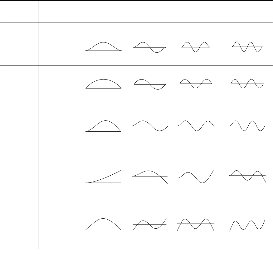
TABLE 9.3
Natural Frequency Coefficients, Mode Shapes, and Node Points for Cases 1 through 5 in Table 9.2.
Boundary
n 1 n 2 n 3 n 4
Conditions
n
/p
‡
1.5056 2.4998 3.5
4.5
(n 0.5, n 4)
Case 1
Clamped- Mode shapes
clamped
Node points
*
None 0.5 0.3585, 0.642 0.279, 0.5, 0.721
n
/p
‡
1234 (n, n 4)
Case 2
Hinged- Mode shapes
hinged
Node points
*
None 0.5 0.333, 0.667 0.25, 0.5, 0.75
n
/p
‡
1.25 2.25 3.25
4.25
(n 0.25, n 4)
Case 3
Clamped- Mode shapes
hinged
Node points
*
None 0.5575 0.386, 0.692
0.295, 0.529,
0.768
n
/p
‡
0.5969 1.4942 2.5002
3.500
(n 0.5, n 4)
Case 4
Clamped- Mode shapes
free
Node points
*
None 0.783 0.504, 0.868
0.358, 0.644,
0.906
n
/p
‡
1.5056 2.4998 3.500 4.500
(n 0.5, n 4)
Case 5
Free-free Mode shapes
Node points
*
0.224, 0.776 0.132, 0.5, 0.868
0.094, 0.356, 0.0735, 0.277, 0.5,
0.644, 0.906 0.723, 0.927
‡
The natural frequency f
n
in Hertz as a function of
n
is given by Eq. (9.94).
*
Values of h not including the boundaries.
locations of these node points that for n 1, 3, . . . the mode shapes are sym-
metric; that is, for the odd numbered modes
In other words, when the beam is “folded” about h 0.5 (the beam’s mid-
point) the mode shape from both halves overlap. For n 2, 4, . . . , the node
shapes are asymmetric; that is, for the even numbered modes
W1h 2 W11 h2 0 h 0.5

The symmetry and asymmetry of the mode shapes are due to the symmetry in
the boundary conditions; that is, they are the same at each end of the beam. In
general, mode shapes do not exhibit these symmetric and asymmetric prop-
erties. In Table 9.2, these are Cases 3, 4, and 6 through 10. However, Cases 8
and 9 of Table 9.2 will have symmetric mode shapes if the values of the spring
stiffness at their respective ends are equal.
Nodes of the different beam modes are important for determining the lo-
cations of sensors and actuators on a beam. If one wishes to actuate a certain
mode, then one should locate the actuation source away from the nodes of a
mode. Alternatively, if one wishes to sense a certain mode by using a sensor,
then one should avoid placing the sensor at the nodes of the mode of interest.
Hence, if one would like to use a displacement sensor to sense the first three
modes of a beam clamped at each end, it is clear from Case 1 of Table 9.3 that
the sensor should be located away from h 0, 0.358, 0.5, 0.642, and 1.0.
Strain-mode shapes Thus far, we have discussed displacement-mode
shapes. One can also plot a strain-mode shape, which shows how the axial
strain of a mode due to bending vibrations changes along the length of the
beam. Based on Eq. (9.8), we note that the axial strain is proportional to the
second derivative of the displacement. Hence, the strain-mode shape associ-
ated with the nth nondimensional frequency coefficient
n
is determined from
Eq. (9.100) as
(9.101a)
where the different derivatives on the right-hand side are evaluated using
Eqs. (9.84), to obtain
(9.101b)
To determine the appropriate locations of strain sensors, one first uses
Eq. (9.101b) to determine the node points and then chooses locations away
from these node points. From a numerical evaluation of Eq. (9.101b) for the
first mode, the strain node points are at h 0.224 and h 0.776; for the sec-
ond mode, they are at h 0.132, h 0.500, and h 0.868. On comparing
these node points of the strain mode shapes with those of the displacement
mode shapes provided in Table 9.3, it is seen that they mostly occur at differ-
ent locations.
On the other hand, if the beam is hinged at both ends, then from Eq. (2b)
of Table 9.2 we see that W
n
(h) sin(
n
h) and, therefore,
Thus, the node points for the strain mode shapes are identical to the node
points of the displacement mode shapes given for Case 2 in Table 9.3.
d
2
W
n
1h 2
dh
2
2
n
W
n
1
n
h2
d
2
W
n
1h 2
dh
2
2
n
c
S1
n
2
T1
n
2
R
n
1
n
h2 Q
n
1
n
h2d
d
2
W
n
1h 2
dh
2
S1
n
2
T1
n
2
d
2
T
n
1
n
h2
dh
2
d
2
S
n
1
n
h2
dh
2
W1h 2W11 h2 0 h 0.5
9.3 Free Oscillations 579