Astakhov V. Tribology of Metal Cutting
Подождите немного. Документ загружается.

Tribology of the Tool–Chip and Tool–Workpiece Interfaces 137
x
C
s
h
s
(x)
y
P
s
Q
s
Body 1
Body 1
Body 2
Body 2
x
(a)
(b)
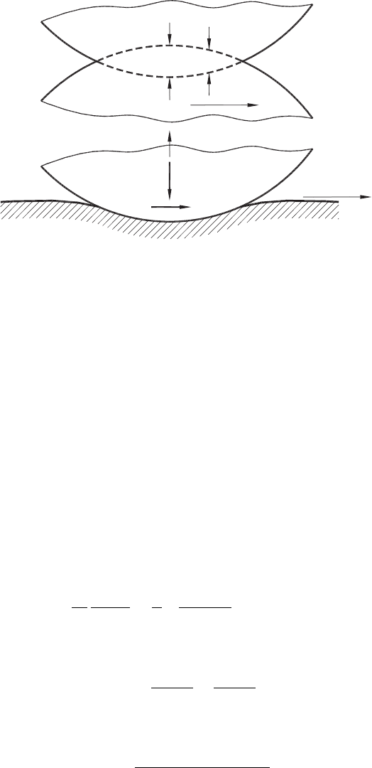
Fig. 3.6. Contact of two bodies: (a) in the undeformed state where they can freely interpenetrate
each other and (b) in the loaded state with no interpenetration permitted.
where
κ
s
=
(
3 − ν
s
)
/
(
1 + ν
s
)
in plane stress (3.10)
κ
s
= 3 −4ν
s
in plane strain (3.11)
ν
s
is the Poisson’s ratio, G is the modulus of rigidity (shear modulus), q
s
(
x
)
= µ
f
p
s
(
x
)
,
where µ
f
is the friction coefficient.
In general, as two bodies are pressed together, deformation must occur so that the
deformed bodies will conform within the contact. If the unloaded state of the bodies
could freely interpenetrate each other, so that the amount of overlap given by h
s
(
x
)
with
maximum c
s
(Fig. 3.6(a)) within the contact patch, the relative y direction displacements
of surface points υ
s1
− υ
s2
must be equal to the degree of surface overlap, so from
Eqs. (3.8) and (3.9) the required displacement is [71]
1
A
s
∂h
s
(
x
)
∂x
=
1
π
p
s
(
ς
)
dς
x − ς
−β
s
q
s
(
x
)
, (3.12)
where
A
s
=
κ
s1
+1
4G
1
+
κ
s2
+1
4G
2
(3.13)
and
β
s
=
Γ
(
κ
s1
−1
)
−
(
κ
s2
−1
)
Γ
(
κ
s1
+1
)
+
(
κ
s2
+1
)
(3.14)

138 Tribology of Metal Cutting
Γ =
G
2
G
1
(3.15)
Thus, A
s
is the measure of the compliance of the bodies, while β
s
, sometimes referred
to as the Dundrus’ constant [71], is a measure of the elastic mismatch of the materials.
When the solution to problems under plane strain conditions is needed, then A
s
and β
s
become
A
s
=
1 − ν
s1
G
1
+
1 − ν
s2
G
2
≡ 2
1 − ν
2
s1
E
1
+
1 − ν
2
s2
E
2
(3.16)
β
s
=
(
1 − 2ν
s1
)
/2G
1
−
(
1 − 2ν
s2
)
/2G
2
(
1 − ν
s1
)
/G
1
+
(
1 − ν
s2
)
/G
2
=
1
2
[(
1 + ν
s1
)(
1 − 2ν
s1
)]
/E
1
−
[(
1 + ν
s2
)(
1 − 2ν
s2
)]
/E
2
1 − ν
2
s1
/E
1
+
1 − ν
2
s2
/E
2
(3.17)
As known from Ref. [71], the elastic constants of the contacting bodies enter the problem
only through the composite parameters A
s
and β
s
. Thus, all pairs of materials yielding
the same values of A
s
and β
s
will have the same solution to the contact problem.
In metal cutting, one (the tool) of the two contact bodies is rigid so the elastic constant
of the other body (the chip, when considering the tool flank–workpiece interface) are
adjusted appropriately. As such
A
s
=
1 − ν
s2
G
2
≡ 2
1 − ν
2
s2
E
2
(3.18)
β
s
=
1 − 2ν
s2
2
(
1 − ν
s2
)
(3.19)
As shown by Hills [71], if the relative tangential displacement of any pair of surface
points is h
s−t
(
x
)
(Fig. 3.6(a)), then this displacement is
1
A
s
∂h
s−t
(
x
)
∂x
=
1
π
q
s
(
ς
)
dς
x − ς
−β
s
p
s
(
x
)
(3.20)
It is understood that integrations in Eqs. (3.12) and (3.20) are carried out over the entire
contact zone. Thus, to assure equilibrium with external forces P
s
and Q
s
, the following
should be kept in mind
P
s
=−
p
(
ς
)
dς (3.21)
Q
s
=
q
(
ς
)
dς, (3.22)
where P
s
is a positive compressive force.
Tribology of the Tool–Chip and Tool–Workpiece Interfaces 139
a
s
a
s
P
s
p(x)
Elastic limit
p
x
h
s
(a)
(b)
p
p(x)
(d)
a
s1
a
s1
(c)
r
s
P
s
x
xx
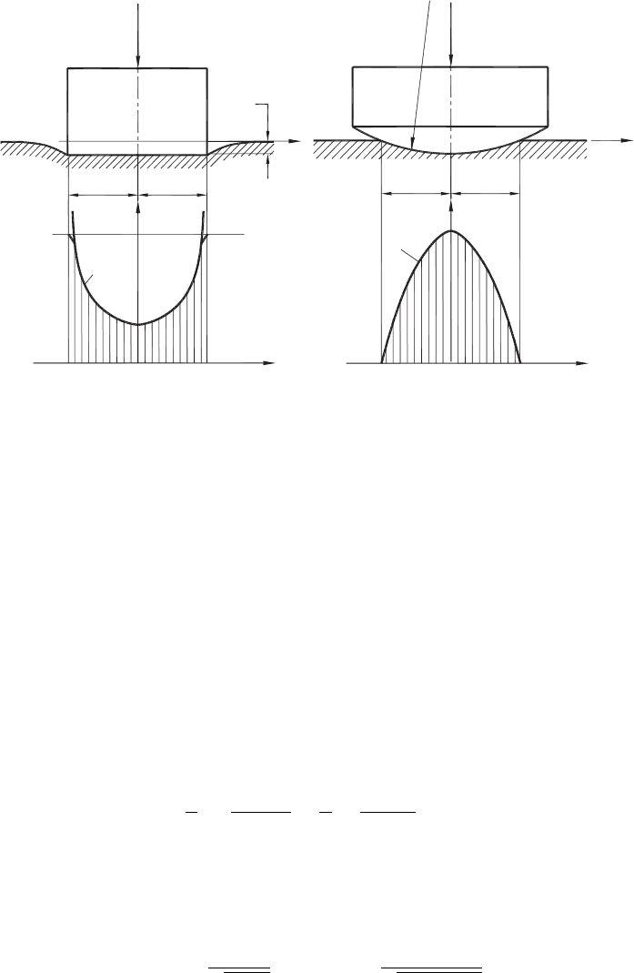
Fig. 3.7. Indentation of a half-plane by: (a) a rigid flat-ended punch and (b) contact stress
distribution, (c) a rigid round-ended punch and (d) contact stress distribution (after Astakhov
and Outeiro [73]).
Poletica [69] was the first researcher who attempted to model the tool–chip contact
problem by analyzing the representation of the tool–chip interface as a rigid, flat-ended
axisymmetric cylindrical punch that is pressed into a viscoelastic material, which can be
regarded as semi-infinite, that is, a half-space as shown in Fig. 3.7(a). The contact patch
is of fixed size, independent of the applied load and determined solely by the width of
the indenter.
Since the displacement of the half-plane, h
s
= constant and no relative motion is allowed,
Eq. (3.12) in normalized coordinates (x = a
s
s, ς = a
s
r) gives
1
π
a
s
−a
s
p
s
(ς)dς
x − ς
=
1
π
+1
−1
p
s
(r)dr
s − r
= 0 (3.23)
and its inversion as in Ref. [71] is
p(s) =
C
√
1 − s
2
or p(x) =
C
1 −
(
x/a
s
)
2
(3.24)

140 Tribology of Metal Cutting
In Eq. (3.24), C, the constant term included as pressure, is singular at each end of the
contact interval. This constant can be found using Eq. (3.21) as
P
s
=
a
s
−a
s
p(x)dx (3.25)
which gives
p
(
x
)
=
P
s
a
s
π
1 −
(
x/a
s
)
2
(3.26)
This is known as the Boussinesq solution [71].
Figure 3.7(b) shows the contact pressure distribution, p(x) calculated using Eq. (3.26).
The contact pressure is singular at the edges of the contact. In reality, the contact pressure
is limited by the elastic limit of the body 2 (the chip), as shown in Fig. 3.7(b). Besides,
the edges of the punch (the tool) are not perfectly sharp.
If the sliding of the punch is allowed so that all points within the contact are slipping
in the same direction, then the shear stress acts over this contact. When the friction
coefficient, µ
f
is constant, this shear stress is defined as
|
q(x)
|
= µ
f
p(x) (3.27)
so that
A
s
π
a
s
−a
s
p
s
(ς)dς
x − ς
+A
s
β
s
µ
f
p(x) = 0 (3.28)
In reality, however, the punch does not have sharp edges as those shown in Fig.3.7(a).
Moreover, its face is not ideally flat. Therefore, the problem of indentation by a general,
convex body should be considered next to approach reality. Figure 3.7(c) shows the rigid
punch having a spherical face of radius r
s
, which is pressed into a viscoelastic material
that can be regarded as semi-infinite, i.e. a half-space. If the contact is sufficiently small
in comparison with the face radius r
s
, then the problem of contact stress distribution
has a direct solution [72]. The distribution of the contact stress for this case is shown
in Fig. 3.7(d). As seen, when x =±a
s1
, the contact pressure becomes zero, and when
x = 0, this pressure is maximum.
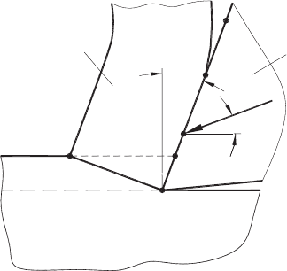
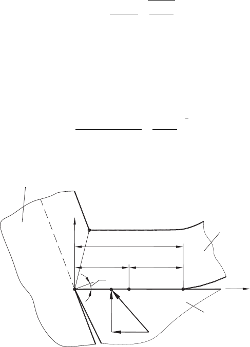
The next step is to start building a model which is closer to the real conditions of the
tool–chip interface. Figure 3.8 shows the following essential features of this interface:
• The resultant cutting force R does not intersect the middle point of the tool–chip
contact length OB. Rather, the line of its action is shifted toward the tool point O,
which represents the projection of the cutting edge.
Tribology of the Tool–Chip and Tool–Workpiece Interfaces 141
O
Chip
Tool
Workpiece
R
A
C
B
E
D
w
ac
g
Fig. 3.8. Some characteristic points at the tool–chip interface (after Astakhov and Outeiro [73]).
• The resultant cutting force R is not applied perpendicular to the tool rake face having
the rake angle γ. Rather, it acts at the so-called angle of action, ω
ac
relative to the
direction of tool–workpiece relative motion [2]. As a result, the normal and shear
stresses act over the tool–chip interface.
• As a result of asymmetrical application of the cutting force, the contact pressure
(stress) distribution is no more symmetrical as in the above-considered case.
• There is relative sliding between the tool and the chip so that the friction force
should be considered in the analysis of the contact stresses at the tool–chip
interface.
Considering Fig. 3.8, one can conclude that the tool point O represents the sharp edge
of the punch. According to Figs. 3.7(a) and (b), a normal stress singularity should be the
case in this point. In reality, however, two factors hamper such a singularity. First, the
cutting edge is never perfectly sharp and thus the intersection of the rake and the flank
surfaces of the cutting insert is not a line but rather a surface of finite radius (this issue will
be discussed later in this chapter). Second, as discussed in Chapter 1, a zone of plastic
deformation in the workpiece forms in the vicinity of this point and a crack originates
from the tool point O in each cycle of chip formation. As known from Ref. [36], plastic
deformation and cracks are means of stress relaxation, so the discussed stress singularity
never occurs in reality. Continue to refer to Fig. 3.8, one can see that the other side of the
tool–chip contact (point B) resembles edge points shown in Fig. 3.7(c), i.e. the contact
pressure becomes zero at this point.
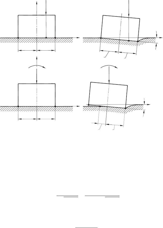
Figure 3.9(a) shows a model of indentation with a flat-face punch and asymmetrical
loading of the punch by force P
s
applied at point D. As seen, the line of action of force
P
s
does not pass through the middle point of the contact length (the xy coordinate origin).
Points O, D and B corresponds to those shown in Fig. 3.8. The asymmetric application
of P
s
results in asymmetric deformation, as shown in Fig. 3.9(b).
142 Tribology of Metal Cutting
a
s
a
s
P
s
x
B
O
D
a
s
a
s
x
B
P
s
D
O
O
1
y
ζ
p
M
s
P
s
y
x
a
s
a
s
E
O
O
1
a
s
M
s
B
P
s
x
E
O
a
s1
(b)(a)
(c) (d)
z
p
Fig. 3.9. Indentation of a half-plane by asymmetrically-loaded punch: (a) original model unre-
formed and (b) deformed configurations; (c) modified model undeformed and (d) deformed
configurations (after Astakhov and Outeiro [73]).
The contact stress distribution for the considered case was studied by Muskhelishvili
[72], who obtained the following exact solution
p(x) =
P
s
π
a
2
s
−x
2
−
4G
2
c
s
x
(
κ
s
+1
)
a
2
s
−x
2
, (3.29)
where c
s
is
c
s
=
M
s
(
κ
s
−1
)
2πG
2
a
2
s
(3.30)
If the sliding of the punch is allowed so that all points within the contact are slipping in
the same direction and when the friction coefficient, µ
f
is constant, the stress distribution
Tribology of the Tool–Chip and Tool–Workpiece Interfaces 143
becomes
p(x) =
cos πρ
s
π
(
κ
s
+1
)
P
s
(
κ
s
+1
)
−8πG
2
c
s
ρ
s
a
s
−4πG
2
c
s
x
(
a
s
−x
)
1
2
+ρ
s
(
a
s
−x
)
1
2
−ρ
s
, (3.31)
where
ρ
s
=
1
π
arctan µ
f
κ
s
−1
κ
s
+1
(3.32)
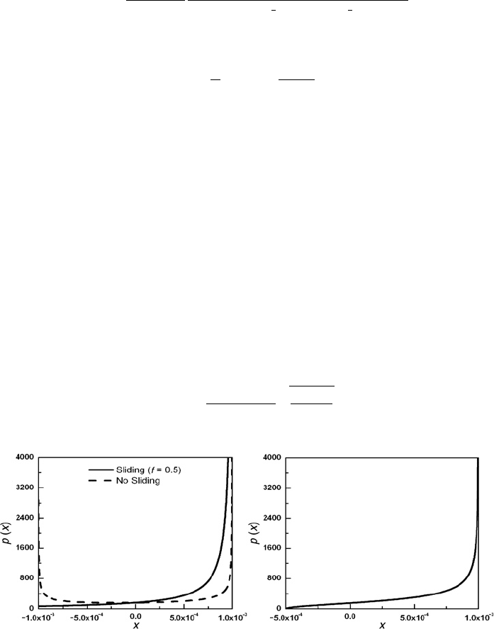
It follows from Eqs. (3.29) and (3.31) that when x =±a
s
, the contact pressure p(x) =
∞ as in Eq. (3.26). However, the distributions given by Eqs. (3.29) and (3.31) are
characterized by significant asymmetry as seen from Fig. 3.10(a) [73]. This figure shows
that when the sliding with friction is allowed, the contact stress, p(x), is no more singular
at the punch rear edge, but it tends to zero. Moreover, the accounting for friction (allowing
the sliding at the tool–chip interface) does not affect this distribution significantly.
The further development of this model is shown in Fig. 3.9(c) where the force is shifted
to the center of the punch and thus the moment M
s
is applied to compensate for this shift.
As such, this moment causes the angular punch displacement characterized by angle ζ
p
and the force P
s
causes the displacement of the punch in the y direction (the vertical
displacement), as shown in Fig. 3.9(d). As seen, this model is obtained assuming that the
moment M
s
is great enough such that the point E is not in contact with the workpiece and
the contact length is no more axisymmetrical. Rather, it may be thought of as consisting
of two parts, a
s1
and a
s
, as shown in Fig. 3.9(d). Studying such a contact problem, Galin
[74] obtained the following analytical solution for the contact stress distribution.
p(x) =
2P
s
π
(
a
s
+a
s1
)
x + a
s1
a
s
−x
(3.33)
(a) (b)
Fig. 3.10. Contact stress distribution (p(x)) produced by applying asymmetrical loading over the
punch: (a) original model sliding with friction is allowed and not allowed, (b) modified model with
an asymmetrical contact length for the original model. (Conditions: a
s
= 1×10
−3
m, P
s
= 0.5N,
µ
f
= 0.5, E
s2
= 210 GPa, ν
s2
= 0.3) (after Astakhov and Outeiro [73]).
144 Tribology of Metal Cutting
As seen, if x =−a
s1
then p
(
x
)
= 0 and if x = a
s
then p
(
x
)
=∞. Equation (3.33) does
not include M
s
directly. This moment is accounted for by a
s1
, which is a function of M
s
.
Figure 3.10(b) [73] shows the contact stress distribution, p
(
x
)
, produced in the case of an
asymmetrical contact length. This distribution is similar to the case of full symmetrical
contact with sliding, as shown in Fig. 3.10(a). However, in the case of the asymmetrical
contact length, the stress at point B (Fig. 3.9(d)) is zero.
Although the above-discussed model provides some insight on the contact stress distri-
bution, it is obviously still far from reality because the chip can hardly be modeled by
the half plane representation used in the model. To improve the model, a 3D problem
of contact of a rigid profile with elastic strip should be considered as the next logical
step in model development [69]. Figure 3.11 shows such a model. Using a general form
of solution obtained by Muskhelishvili [72] as applied to the considered case, one can
obtain the following expression for the contact stress distribution
p(x) =
2N
πd
w1
l
c
l
c
−x
x
(3.34)
where l
c
is the contact length, d
w1
is the chip width.
More accurate results can be obtained if friction over the contact length is considered.
As such, the boundary conditions for the stress and displacement should be as follows:
if x<0orx ≥ l
c
then p(x) = σ
c
= 0 and τ
c
= 0. As such
p(x) =
2N
πd
w
l
c
(
1 − 2ρ
s
)
l
c
−x
x
1
2
−ρ
s
, (3.35)
O
Chip
Tool
Workpiece
A
O
1
y
x
B
E
F
R
D
l
c
l
c
/2l
c
/2
N
g
Fig. 3.11. Contact length and its parts (after Astakhov and Outeiro [73]).

Tribology of the Tool–Chip and Tool–Workpiece Interfaces 145
where ρ
s
calculates using Eq. (2.66). As seen, when µ
f
= 0, ρ
s
= 0 and Eq. (3.35)
becomes equivalent to Eq. (3.34).
For convenience, the stress at the tool–chip interface can be represented as the product
of two factors
p(x) = q
N
p
1
(x), (3.36)
where the first one,
q
N
=
N
d
w
l
c
(3.37)
is the mean contact stress at the tool–chip interface, and the second one is a dimensionless
function
p
1
(x) =
2 cos πρ
s
π
(
1 − 2ρ
s
)
l
c
−x
x
1
2
−ρ
s
(3.38)
characterizing the distribution law of the normal pressure over this interface. Equation
(3.38) can be modified further if a new variable ψ
s
= x/l
c
is introduced. As such
p
1
(ψ
s
) =
2 cos πρ
s
π
(
1 − 2ρ
s
)
1 − ψ
s
ψ
s
1
2
−ρ
s
(3.39)
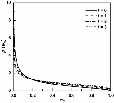
Figure 3.12 shows the distribution of the contact pressure, p
1
(ψ
s
) obtained under dif-
ferent friction coefficients [73]. This figure shows that accounting for friction (allowing
the sliding at the tool–chip interface) does not affect this distribution significantly.
One problem about the exact location of the point of application of the penetration force
on the tool rake face remains unsolved. To resolve this problem, an FEM model for the
case shown in Fig. 3.11 was developed using ANSYS commercial FEA software [73].
The developed FEM model utilized the work material properties
(
E, ν
)
, the tool geometry
(
γ
)
and the results obtained from orthogonal cutting tests (forces, N and F, the final
angle of the surface of the maximum combined stress (known as the shear angle), and the
tool–chip contact length, l
c
). The results for the tool–chip contact stress distribution and
equivalent stress distributions in the workpiece and in chip are shown in Figs. 3.13(a) and
(b) for the following conditions: E = 196 GPa, ν
s
= 0.26, N = 1550 N, F = 1215 N,
γ = 0
◦
, l
c
= 0.712 mm, l
1
= 0.284l
c
. As seen, the maximum stress is found to be at the
region of the cutting edge. This stress decreases exponentially towards the point of chip
separation where this stress is zero.
Interface stress distributions based on the system model. Based upon the system
approach in metal cutting [36,75], this section aims to explain the nature of a significant
146 Tribology of Metal Cutting
Fig. 3.12. Contact stress distribution (p
1
(ψ
s
)) produced by applying asymmetrical loading over
the punch and considering an asymmetrical contact length, for different friction coefficients
(Conditions: a
s
= 1 ×10
−3
m, a
s1
= 5 ×10
−4
m, P
s
= F
N
= 0.5N,µ
f
∈
[
0, 3
]
, E
s2
= 210 GPa
and ν
s2
= 0.3) (after Astakhov and Outeiro [73]).
scatter in the reported stress distributions at the tool–chip interface by studying the
dynamics of stress formation and distribution at this interface.
Finite element simulation makes it possible to establish the distributions of the normal
and shear stress at the tool–chip interface, as well as the dynamics of these distributions
within a chip formation cycle. It is instructive to trace the above-mentioned distributions
by applying FEM analysis with incremental loading. The detailed procedure of such
a simulation is developed by Astakhov [36]. Some relevant results obtained are now
considered.
The shear stress distribution at the beginning of each new chip formation cycle is shown
in Fig. 3.14. As seen, this distribution within the tool–chip interface has two distinctive
regions. In the first region, the shear stress distributes uniformly and increases with the
applied load. Furthermore, both the length of this region and the stress magnitude do not
change with the rake angle. In contrast, in the second region, the shear stress decreases
at a rate that is a function of the rake angle.
A comparison of the results shown in Fig. 3.14 with the known results shown in Fig. 3.1(b)
shows that there is no contradiction in the reported results. In other words, all the reported
shear stress distributions (curves 1 to 6 in Fig. 3.1(b)) at the tool–chip interface may occur
as being considered at different instants over a chip formation cycle and under different
cutting conditions.