Astakhov V. Tribology of Metal Cutting
Подождите немного. Документ загружается.

Tribology of the Tool–Chip and Tool–Workpiece Interfaces 127
It is true that, in general, the coefficient of friction for sliding surfaces remains con-
stant within wide ranges of the relative velocity, apparent contact area and normal load.
In contrast, in metal cutting, the coefficient of friction varies with respect to the normal
load, the relative velocity and the apparent contact area. The coefficient of friction in
metal cutting was found to be so variable that Hahn [15,16] doubted whether this term
served any useful purpose. Moreover, Finnie and Shaw [6] have concluded that the con-
cept of the coefficient of friction is inadequate to characterize the sliding between chip
and tool and thus recommended to discontinue using the concept of the coefficient of
friction in metal cutting. An extensive analysis of the inadequacy of the concept of the
friction coefficient in metal cutting was presented by Kronenberg (pp.18–25 in [4]) who
stated “I do not agree with the commonly accepted concept of coefficient of friction in
metal cutting and I am using the term ‘apparent coefficient of friction’ wherever feasible
until this problem has been resolved.” Unfortunately, it has never been resolved although
more than 40 years have passed since this statement of Kronenberg.
To model friction conditions in metal cutting and thus to determine the real value of
the friction coefficient, a large number of theoretical analyses [17–31] have been carried
out to determine the influence of various parameters on the interfacial friction. Despite
the improvements made in the modeling of friction in machining processes over the last
30 years, there are still a number of limitations so that the results of these studies are
hardly applicable to metal cutting.
In the author’s opinion, the most severe drawbacks of the discussed theoretical
considerations are:
• At the interface, the soft material is always assumed to be rigid, perfectly plastic,
incompressible and isotropic at all stages of deformation. Moreover, no superficial
and in-depth residual stresses due to previous deformation can be accounted for.
Obviously, this is not the case in metal cutting and particularly at the tool–chip
interface.
• The approaches known so far consider only two-dimensional asperity interaction
ignoring the three-dimensional nature of asperities and actual multi-asperity inter-
action. The shape of the asperity should be well defined so that its initial and final
point should lie on the same line parallel to the direction of relative motion. More-
over, this shape determines the slipline field where the discontinuity of tangential
velocity leads to infinite calculated strains. No wonder the chip formation model
predicts an increase in the coefficient of friction with improved lubrication [22].
• The sliding speed was not considered to be an important factor. The temperature and
strain rate effects are poorly accounted for. The sliding speed even in the verifica-
tion experiments was 0.3 mm/s and this is obviously way below the sliding speeds
found at the tool–chip interface. It was also found that the strains determined from
the experimental flow fields are significantly lower than those calculated from the
model [25].
A number of experimental techniques and tests for evaluating the interfacial friction in
metal cutting have been developed. Many of these tests actually aim to evaluate properties
of the metalworking fluids and thus are known as the lubricity tests [32]. Each has its

128 Tribology of Metal Cutting
own inherent advantages and limitations. Lubricity tests can be broadly divided into three
groups [32]. One group is based upon simple rubbing or rolling action. Another group
is based upon metal removal or chipmaking processes. The final group incorporates
forming or drawing of a metal sheet. It was soon recognized, however, that, because of
the complexity of field conditions, no simple test machine can simulate the lubrication
requirements for different machining operations. Therefore, it is rather difficult, or even
impossible, to correlate bench test data with the actual performance [32].
To understand the problem with experimental determination of the friction coefficient,
one should refer to the force diagram developed by Merchant [1] and shown in Fig. 1.1(a).
Since Merchant assumed Coulomb friction is the case in metal cutting, the following
expression for the friction coefficient was obtained from the force diagram shown in
Fig. 1.1(d)
µ =
F
N
=
F
T
+F
C
tan γ
F
C
−F
T
tan γ
(3.4)
It directly follows from Eq. (3.4) that the friction coefficient can be calculated using the
friction and normal forces obtained experimentally by resolving the measured cutting
and trust components of the cutting force. The friction coefficient thus obtained does not
match with common experience. This was first found by Kronenberg in 1927 (p.18 in
[4]). Unfortunately, Merchant, who conducted his research 20 years later, did not pay
attention to the first edition of Kronenberg’s book.
3.2.2 Contact stresses distribution – reported results
Later research has been aimed at obtaining a better understanding of the conditions at
the tool–chip interface by studying the distribution of the normal and shear stress at
this interface. A variety of experimental techniques including photoelastic tools, split-
tool dynamometer, transparent tool for the direct observation of the tool–chip interface,
metallurgical examination of “quick-stop” chip-section including experimental slipline
field method have been developed [2,33–39].
Photoelastic method. The pioneers in the field of photoelastic analysis of orthogonal
metal cutting, such as Coker and Filon [40] and Zeichev [41] have generally used a
photoelastic work material in their studies. This has shortcomings as the work material
undergoes plastic deformation as shown by Frocht and Thomsen [42] and Ocushiri and
Fukuii [43] who have used a photoelastic material as a cutting tool, which was pressed
against the already-made chip.
Andreev [44] and Kattwinkel [45] were probably the first scientists who obtained some
meaningful stress distributions at the tool–chip interface using a photoelastic tool [38].
Andreev [44] pointed out that the whole contact length l
c
is divided into two distinc-
tive parts of approximately equal length: the plastic part that extends from the cutting
edge to the middle of the contact length (or the length of the tool–chip interface) and
the elastic part from the middle of contact to the point of chip separation from the
Tribology of the Tool–Chip and Tool–Workpiece Interfaces 129
Normal stress
0
Distance from the cutting edge
Shear stress
1
1
2
2
3
(a)
(b)
3
4
6
5
4
5
6
0
0 0.5l
c
l
c
Distance from the cutting edge
0 0.5l
c
l
c
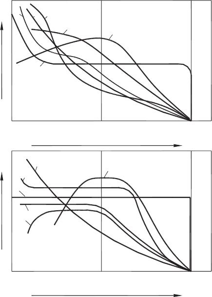
Fig. 3.1. Stress distributions at the tool–chip interface reported in literature: (a) normal stress and
(b) shear (tangential) stress (after Astakhov and Outeiro [73]).
tool–rake face. The results obtained indicate that the normal stress, being zero at the point
of chip separation, increases exponentially towards the cutting edge (curve 1, Fig. 3.1(a)).
The distribution of the shear stress obtained by Andreev is shown in Fig. 3.1(b), curve 1.
Kettwinkel, using a similar experimental technique, obtained similar distribution of the
normal stress (curve 1, Fig. 3.1(a)). He found, however, that the shear stress, after reach-
ing the maximum value at the middle of the contact length then decreases toward the
cutting edge (curve 2, Fig. 3.1(b)).
Takeyama and Usui [46] studied the stress distribution along the tool–chip interface by
measuring the cutting forces on tools with various contact lengths. Their result for the
normal stress is shown by curve 2 in Fig. 3.1(a) and for the shear stress by curve 3 in
Fig. 3.1(b). Later on, Usui and Takeyama [7] improved the accuracy of their experiments
and thus concluded that the distribution of the normal stress is as shown by curve 3 in
Fig. 3.1(a) and that of the shear stress is as shown by curve 4 in Fig. 3.1(b). The same
experimental technique was used by Chandrasekaran and Kapoor [47]. Trying to under-
stand the influence of tool geometry, they used photoelastic tools of different rake angles.
130 Tribology of Metal Cutting
They found that the contact length l
c
is inversely proportional to the rake angle. For pos-
itive rake angles (0, 10 and 20
◦
), the distribution of the shear stress corresponds to that
given by curve 3 in Fig. 3.1(b) but when the rake angle was negative, the distribution
given by curve 5 in Fig. 3.1(b) was the case. For all the studied tools which had positive
rake angles, the maximum of the shear stress was found to be very nearly that of the
shear yield strength of the work material. In their opinion, a significant difference in the
curves of normal stress distribution shows (curve 4 corresponds to a +20
◦
rake angle,
curve 5 corresponds to –10
◦
) that there is some pronounced differences in the case of a
negative rake tool.
Further studies using photoelastic tools [48,49] yielded different results. Amini [48]
concluded that both the normal and the shear stresses increase in a non-linear manner
from the point of chip separation towards the cutting edge. Ocusima et al. [49] found
that the shear stress distribution is similar to that of the given by curve 1 in Fig. 3.1(b)
and remains constant over approximately two-thirds of the contact length l
c
. The normal
stress, being approximately equal to the shear stress at the cutting edge, reaches its
maximum at the mid point of the contact length and then decreases gradually to zero
(curve 6 in Fig. 3.1(a)).
Although the above-discussed experimental studies using the photoelastic method were
great attempts to determine the stress distributions during machining, a number of points
of criticism on these results remain open. The major concerns are with the cutting speeds
used in the test which are thousand times lower (due to extremely low hot hardness of
the tools used) than those found in practice. As a result, there is no ground to believe
that the real tribological characteristics of the tool–chip contact, namely the mode of
deformation; the maximum temperature and temperature distribution; relative velocity
of the contacting bodies; abrasion, adhesion, diffusion, and chemical interactions [39],
would be even close to those in these studies. Moreover, it is not possible to determine
accurately the contact stresses immediately adjacent to the cutting edge because the
contact stresses at the tool flank cause distortion of the isochromatic fringes in this
region [50].
Bagchi and Wright [37,51] overcame the problem with tool hot hardness by using a single
crystal sapphire tool although the stress birefringence effect in sapphire is relatively weak
and, of course, sapphire is inherently brittle. Despite these difficulties, they were able to
machine steel and brass specimens at speeds of up to 75 m/min and at a maximum feed
rate of 0.381 mm/rev to study the effect of speed and feed on stress distributions [37].
It was found that the normal and shear stress distributions qualitatively resemble those
obtained by Chandrasekaran and Kapoor [47]; the cutting speed does not have significant
influence on the peak normal stress while the feed and the uncut chip thickness do.
Split tool method. The method was first completely described and used by Loladze
[37,52,53]. The method is based on the use of a composite cutting tool having the
cutting wedge divided into two parts. The principles of design of the split tool is shown
schematically in Fig. 3.2. The cutting wedge and thus, the tool rake face is divided into
two parts, namely T
1
and T
2
. During the test, the forces acting only on the part T
1
were
measured. During the experiment, the length of T
2
was incrementally increased from the
smallest possible value up to l
c
.
Tribology of the Tool–Chip and Tool–Workpiece Interfaces 131
F
Ni
F
fi
T
2
T
1
Chip
Cutting
direction
l
i
l
c
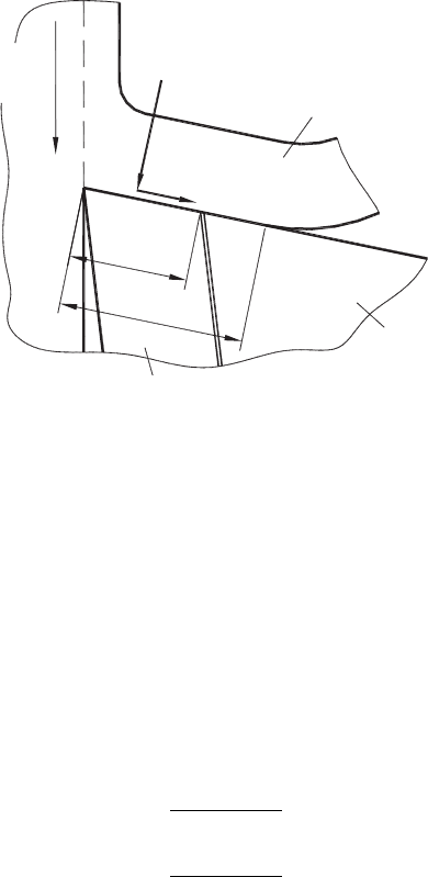
Fig. 3.2. Principle of measurement of stress distribution using the split tool technique.
The determination of the stress distribution consists of the following steps:
• A cutting test is carried out with the part T
2
having length l
i
, and the normal F
Ni
and frictional F
fi
forces acting on this part are measured.
• The length l
i
is decreased to l
i+1
and the next test is carried out under the same
cutting conditions which yields in F
Ni+1
and F
fi+1
.
The mean normal stress σ
c
and shear stress τ
c
acting at the interface having length
(
l
i+1
−l
i
)
were calculated as
σ
i
=
F
Ni+1
−F
Ni
d
w
(l
i+1
−l
i
)
(3.5)
τ
i
=
F
fi+1
−F
fi
d
w
(l
i+1
−l
i
)
(3.6)
Conducting his experiments using the above-described technique, Loladze [52] found
that the distributions of the normal and shear stresses correspond qualitatively to those
found by Andreev (curve 1, Fig. 3.1(a) and curve 1, Fig. 3.1(b), respectively). The values
of the maximum normal stress varied from 900 to 1600 MPa for different steels used in
the tests and were strongly related to the yield strength of the work material. In each
case, the maximum normal stress near the cutting edge was higher than the yield strength
of the work material by a factor greater than two. This maximum stress increases to a
small extent with the cutting speed and feed, and decreases as the rake angle increases.
Unfortunately, Loladze and subsequent researches did not pay attention to this important
experimental finding that resulted from well-prepared and precisely conducted cutting
tests.
132 Tribology of Metal Cutting
Kato et al. [54] conducted a wide range of cutting experiments using a split tool
dynamometer. Their results for different work materials can be qualitatively described
by the following curves in Fig. 3.1:
• For work hardened and perfectly annealed aluminum, copper and lead–tin alloy,
the normal stress distribution corresponds to curve 4 (Fig. 3.1(a)); the shear stress
distribution corresponds to curve 3 (Fig. 3.1(b)). Surprisingly, the normal and shear
stresses at the plastic part of the tool–chip contact were the same for work hardened
and for perfectly annealed aluminum although the full contact and plastic contact
lengths were twice greater for the latter. Moreover, the shear stress was found to be
25% higher than the normal stress at the plastic part of the tool–chip contact.
• For zinc, the normal and shear stresses closely (qualitatively and quantitatively)
follow each other and their distribution corresponds to curve 1 (Fig. 3.1(a)) and
curve 6 (Fig. 3.1(b)), respectively.
In the author’s opinion, the most important conclusion that can be drawn from these
results is as follows. Because the study had only one process variable, namely the work
material (all other parameters are kept the same), the state of stress in the deformation
zone and thus at the tool–chip interface should be qualitatively the same. Therefore,
if metal cutting, as it is believed now [2,34,35,37,55–60], is accomplished by pure
(or simple) shearing, the normal and shear (tangential) stress distributions should be
the same for all ductile materials. Moreover, the shear and normal stresses should be
uniquely related so that the shear stress should not exceed 0.7σ. The experimental results
obtained do not support this belief. For example, Barrow et al. [50] used a split tool to
obtain the stress distributions while machining a nickel–chromium alloy within a wide
range of cutting speeds and feeds. It was found that for some cutting conditions, the peak
shear stress was approximately equal to the peak normal stress while the magnitude of
this peak was found to depend on the cutting conditions. As argued by Astakhov [36],
the triaxial state of stress is the real phenomenon of metal cutting and, since different
materials react differently on the degree of triaxiality, they exhibit different strain–stress
behavior under the same state of stress.
Further researchers [58,61,62] conducted a great number of experimental studies with
different work and tool materials in order to determine particular values of maximum
normal and shear stress and their distribution along the contact length. Since more sen-
sitive techniques for force measurement became available, the fluctuation of the cutting
forces became evident. However, instead of understanding the nature of such fluctua-
tions (as argued above, this fluctuation is a result of cyclical nature of the chip formation
process), they just used smoothing or averaging of the experimental forces to obtain
steady-state stress distributions [63].
Experimental slipline field method. In order to determine the distribution of the nor-
mal and shear stresses at the tool–chip interface, Roth and Oxley [64] analysed an
experimental flow field obtained under plain strain conditions using the slipline field
technique. According to their perception, a single slipline field which would describe
the flow in the two deformation zones in metal cutting (the primary deformation zone
which stands for the shear plane and the secondary deformation zone which stands for the
Tribology of the Tool–Chip and Tool–Workpiece Interfaces 133
plastic part of the tool–chip contact) could be constructed using experimental flow field
and the measured cutting forces. The following drawbacks of this method are listed as
follows:
• The cutting speeds used to obtain a specimen to study the experimental slipline field
are more than 1000 times lower than those used in the practice of cutting of the same
work material. For example, the cutting speed was 0.0125 m/min for free machin-
ing steel SAE 1112 in Roth and Oxley experiments [64] while the recommended
cutting speed used for the same work material exceeds 300 m/min (Table 21.2 in
Ref. [65]). As well-discussed by Zorev [2], there is no similarity between the cutting
processes at low cutting speeds (see Chapter 2 “Experimental studies of chip for-
mation and contact processes on the tool face at low cutting speeds” and Chapter 4
“Experimental studies of chip formation and contact processes on the tool face at
high cutting speeds” in Zorev’s book [2]).
• In order to apply the slipline method, simple shearing was assumed to be the prime
mode of deformation in the primary and secondary deformation zones which is
obviously not the case in metal cutting [36]. The state of stress in the mentioned
deformation zones has not been analysed, hence the z component of the normal
stress was ignored.
• The method is extremely subjective. For example, the crucially important parameters
namely the radius of chip curvature and the tool–chip contact length were a subject
of assumptions rather than results of measurements.
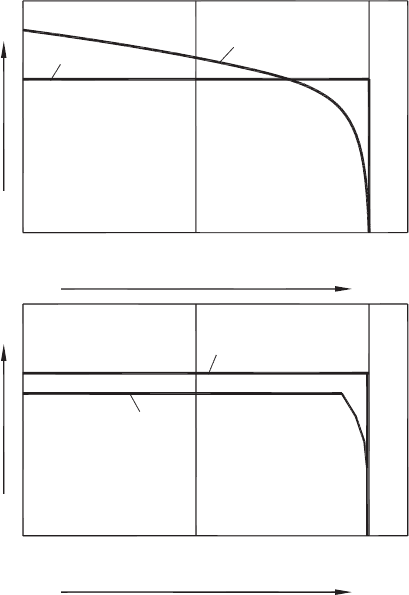
The normal and shear stress distributions obtained by Roth and Oxley [64] are qual-
itatively shown in Fig. 3.3(a) by curve 1 and in Fig. 3.3(b) by curve 1. As seen, a
stress singularity exists at the point of chip separation from the rake face that cannot be
physically justified.
Later, Oxley in Chapter 7 “Predictive machining theory based on a chip formation model
derived from analyses of experimental flow fields” of his book [35], concluded that
“a plastic state of stress exists in the chip over the full contact length and that the
deformation in the chip can be represented by a rectangular plastic zone with no sliding
at the interface.” (p. 100 in Ref. [35]). Further followers of this method tried to take
into account the so-called ploughing force components due to the radius of the cutting
edge [38]. After a number of assumptions, the distributions of the normal and shear
(tangential) stress were obtained to be uniform over the tool–chip contact length, as
shown in Figs. 3.3(a) and (b), curves 2. These results are in direct contradiction with
those of previous experimental studies where the division of the contact length into two
distinctive parts (plastic and elastic) was clearly observed. Moreover, the singularity of
stresses at the point of chip separation from the rake face has never been explained. These
distributions of the normal and shear stresses suggest that a constant friction coefficient
is the case at the tool–chip interface according to Eq. (3.3).
A critical analysis of the above-mentioned and other studies related to stress distribution
beyond those analysed above (for example, Refs. [2,34,57,66–69]) shows that it is quite
possible that actual stresses and stress distributions may have not yet come to light due
to a significant scatter in the results obtained.
134 Tribology of Metal Cutting
0
0
Normal stress
0.5I
c
(b)
(a)
Shear stress
0
Distance from the cutting edge
1
2
2
1
I
c
0 0.5I
c
Distance from the cutting edge
I
c
Fig. 3.3. Qualitative representation of the normal (a) and shear (tangential) (b) stress distributions
at the tool–chip interface obtained by Roth and Oxley for a free-machining steel (after Astakhov
and Outeiro [73]).
3.2.3 Contact stress distribution – modeling
Experimental evidences. Multiple experimental studies conducted by Zorev [2],
Loladze [52], Poletica [69] and many others conclusively proved that the tool–chip
interface consists of plastic and elastic parts. Figure 3.4 shows that the plastic part of
the tool–chip interface can be clearly observed on the tool rake face. Therefore, the
uniform stress distribution shown in Fig. 3.3 is in direct contradiction with the known
experimental observations.
Zorev [2] studied the length of the plastic part using a quick-stop device and conclu-
sively proved that the whole contact length l
c
is divided into two distinctive parts: the
plastic part, l
c−p
which extends from the cutting edge and the elastic part l
c−e
, from
the plastic part to the point of tool–chip separation. Zorev showed that the contact
length, l
c
is a function of the cutting speed, as shown in Fig. 3.5. Similar experimental
results were obtained by Poletica [69]. Summarizing the results of multiple experiments,
Tribology of the Tool–Chip and Tool–Workpiece Interfaces 135
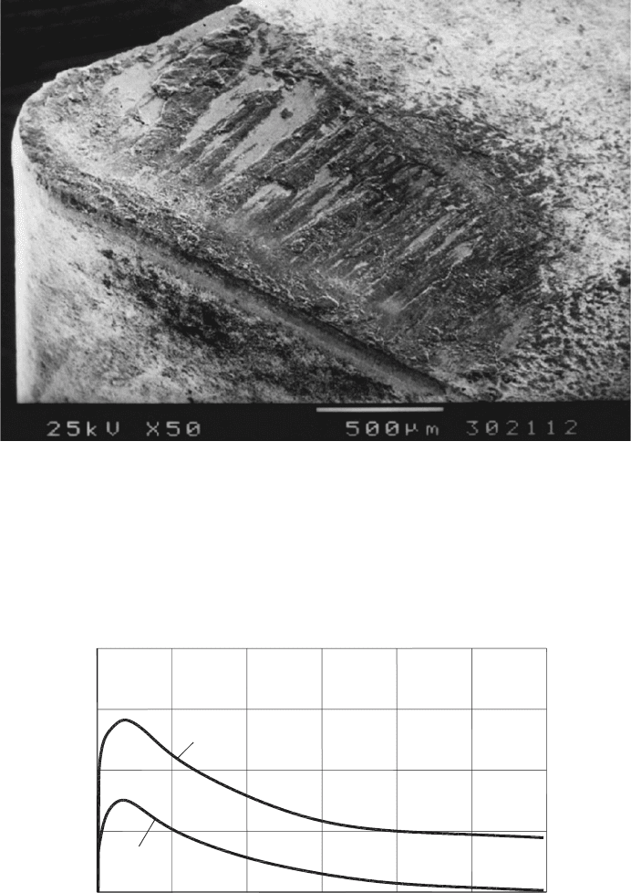
Fig. 3.4. The tool–chip interface consists of two parts, namely plastic and elastic.
1.5
1.0
0.5
n (m/min)
30
l
c
, l
c−p
(mm)
2.0
60 90 120 150
l
c−p
l
c
Fig. 3.5. Influence of cutting speed (ν) on the tool–chip contact length (l
c
) and on the plastic part
l
c−p
of the tool–chip contact length. Orthogonal cutting, work material – steel 4130, rake angle
γ = 5
◦
and uncut chip thickness t
1
= 0.15 mm.

136 Tribology of Metal Cutting
Abuladze [70] proposed the following expression to calculate the length of the plastic
part of the tool–chip interface
l
c−p
= t
1
[
ζ
(
1 − tan γ
)
+sec γ
]
(3.7)
Model and FEM analysis. The contact problem at the tool–chip interface can be mod-
eled as the contact of two bodies made of dissimilar materials. As such, one body
deforms elastically within the contact interface (the tool), and the other body (the chip)
contains elastic and plastic regions within this interface. Moreover, there is relative slid-
ing between these two contacting bodies and thus the traction develops over the contact
length. In the considered case of the tool–chip contact, it is not simple to determine the
exact contours of the deformed surfaces and other boundary conditions so that the exact
solution of the stated contact problem is rather difficult. Therefore, simplifications have
to be introduced to develop a suitable model.
All real contacts, like all real engineering components, are three-dimensional, and there-
fore theoretically demand a solution in the three-dimensional theory of elasticity of
elastoplasticity [71]. However, there are some simple cases where it is feasible to approx-
imate the geometry to one or two dimensions. As discussed in Chapter 1, orthogonal
cutting is always considered as a two-dimensional problem. Thus, in order to investi-
gate the tool–chip contact problem, plane contact problems will be considered, i.e. those
where it is assumed that displacements are restricted to a single plane, the xy plane.
Among the two-dimensional contact problems known, those where the contacting bodies
are considered to be half-planes, i.e. semi-infinite bodies with remote boundaries are
looked at, provided that the width of the resulting contact is negligible in comparison with
the bodies’ radii of curvature. Contacts where this is so are said to be non-conformal [71].
A wide range of non-conformal contact problems may be readily solved in two stages.
First, the mixed boundary value problem (where displacements are specified within the
contact, and the remainder of the free surface is free of tractions) is reduced to an elasticity
problem of the first kind, i.e. where the tractions are specified everywhere. Second,
the interior stress field due to these tractions is found by applying the Muskhelishvili
potential [72].
Figure 3.6 shows the general class of contact problems. Subscripts 1 and 2 will be
added to the elastic constant relating to the upper and lower bodies respectively and a
mathematical sign conversion is adopted for the tractions, i.e. direct tractions (contact
stresses) p
s
(
x
)
are positive tensile and shear tractions q
s
(
x
)
are positive when acting
to the right on the lower body. According to the known results [71], the equations for
displacements υ
s1
and υ
s2
are
∂υ
s1
∂x
=
κ
s1
+1
4G
1
π
p
s
(
ς
)
dς
x − ς
−
κ
s1
+1
4G
1
q
s
(
x
)
(3.8)
∂υ
s2
∂x
=
κ
s2
+1
4G
2
π
p
s
(
ς
)
dς
x − ς
−
κ
s2
+1
4G
2
q
s
(
x
)
(3.9)