ASM Metals HandBook Vol. 8 - Mechanical Testing and Evaluation
Подождите немного. Документ загружается.

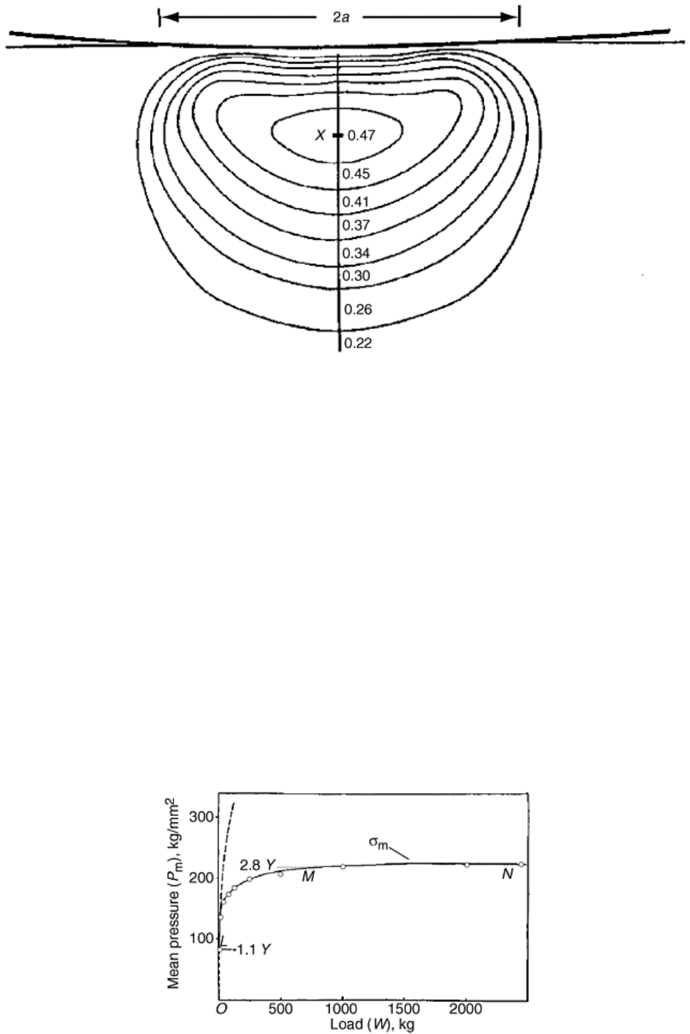
Fig. 4 Elastic defomation of a flat surface on an elastic semi-finite body under a frictionless load, by a
rigid sphere of a large radius, showing the location of maximum shear stress in the bulk material below
the deformed surface. The maximum shear stress occurs at X, 0.5a below the center of the circle of
contact and has a value of about 0.47 P
m
where P
m
is the mean pressure. The contours represent lines of
constant shear stress in the deformed material. Source: Ref 6
If the load is reduced or removed before P
m
reaches the value 1.1Y at X, there will be no permanent deformation
or indentation; that is, there will be a complete elastic recovery. If, however, P
m
exceeds the value 1.1Y, plastic
deformation begins at X, and the plastic region would grow in size at the expense of the elastic-plastic and
elastic regions underlying the indenter. This process will continue until the mean pressure in the plastic volume
reaches a value ≈3Y. If the load is now increased, the indenter penetrates the metal further, and the plastic zone
would expand until the value of P
m
in the newly formed plastic volume again equals ≈3Y. When the equilibrium
is reached between the indenter and the material during indentation, and the plastic flow has stopped, the
indenter load is supported by the elastic stresses in the material. If the load is removed, therefore, there will be
an elastic recovery with a corresponding change in shape of the plastically deformed volume and, hence, that of
the indentation.
The spherical indentation process may be visualized through an experimental trace of pressure-load for
indentations formed in work hardened mild steel by a spherical indenter. In Fig. 5, point L represents the onset
of plastic deformation at a mean pressure corresponding to 1.1Y. The interval L-M represents a gradual increase
in the plastic stress, which ultimately reaches a value ≈3Y corresponding to M-N section of the curve when full
plasticity is attained.
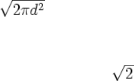
Fig. 5 Experimental pressure-load characteristic of indentations formed in work-hardened mild steel by
a hard spherical indenter. Yield stress of steel, Y = 77 kg/mm
2
. Ball diameter is 10 mm. The broken line is
the theoretical result for elastic deformation. OL, elastic region; LM, elastic-plastic region; and MN, fully
plastic region. Source: Ref 6
Fully Cold Worked versus Fully Annealed Metals. The above discussion has considered ideal plastic metals,
which, by definition, do not work harden during deformation and show a constant yield stress when the linear
strain is increased as in a tensile or compressive test. Metals that have been sufficiently cold worked would
behave in approximately this manner. However, fully annealed, and, in reality, most metals will have a
tendency to work harden during deformation and will be characterized by a continuously increasing yield stress
with increasing strain. The relation P
m
= CY (C ≈ 3), which applies to fully cold worked metals, also holds for
fully annealed metals provided Y denotes the yield stress corresponding to the strain produced during testing,
which is higher than the initial yield stress. The value of C has the same approximate value of 3 as for ideal
plastic metals. Also, P
m
is found to be a function of d/D for fully annealed metals, and therefore, geometrically
similar indentations would give identical hardness values, as for ideal plastic metals. It may be noted here that
the value of C ≈ 3 obtained through slip line analysis as already mentioned has also been recently confirmed
through finite element analysis (Ref 12, 13).
Tabor (Ref 6) showed that the strain, ε, in the plastic region of an indentation is proportional to the ratio d/D
and empirically determined the proportionality constant to be approximately 20 for many metals, thus arriving
at the relation, ε = 20d/D. Combining this equation with the relationship Y = bε
x
, where b and x are constants for
a given metal and x is the strain hardening coefficient, Tabor has shown that W = c
1
d
1
n
= c
2
d
2
n
= c
3
d
3
n
and so on
for indentations made with indenters of different diameters D
1
, D
2
, D
3
… This is Meyer's law, mentioned earlier
and first derived by Meyer empirically. This relation has been shown to hold fairly well for many materials.
The value of n in the Meyer equation is roughly related to the strain hardening coefficient x by the relation n = x
+ 2.
Conical and Pyramidal Indenters (Ref 6). Shortly after the introduction of Brinell hardness testing, Ludwik (Ref
14) proposed hardness testing using a conical indenter and defined the hardness as the mean pressure over the
surface of the indentation. Thus, for an indent with an included angle of 90°, the Ludwik hardness number is
given by:
HL = 4W /
(Eq 13)
where d is the diameter of the impression. This concept is similar to that of Brinell and therefore has no real
physical significance. The true pressure, P, between the indenter and the indentation is given by the ratio of
load to projected area, that is, 4W/πd
2
(similar to Meyer's concept for a spherical indenter), which means that
the Ludwik hardness number is 1/ times the mean yield pressure P. Experiments have shown that Ludwik
hardness is practically independent of the load for a given indenter, though it depends on the cone angle. It is
observed that the yield pressure increases as the cone semi-angle decreases, and the effect may be partially
explained as due to friction between the indenter and the indentation (Ref 15).
The diamond pyramidal indenter was first introduced by Smith and Sandland (Ref 16) and was later developed
by Vickers-Armstrong, Ltd. The indenter is in the form of a square pyramid with opposite faces making an
included angle of 136° with each other. The origin of this value of the angle is traced to the Brinell hardness
testing practice. It is customary in Brinell hardness testing to select loads so that the indentation diameter lies
between 0.25D and 0.5D where D is the indenter diameter. Thus, an average of the two diameters, 0.375D, was
chosen for the indentation diameter as shown in Fig. 6, which also shows the origin of the included angle 136°
of the Vickers indenter. The geometry of the indenter is such that projected area of the indentation is 0.927
times the area of the contact surface. Since Vickers hardness, HV, is defined as the load divided by the surface
area of the indentation, the yield pressure, P, is related to the Vickers hardness number by the relation HV =
0.927P.
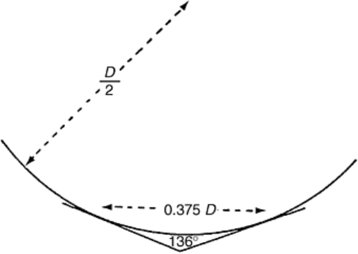
Fig. 6 Relationship between the 136° included angle between the opposite faces of a Vickers indenter and
the spherical Brinell indenter of diameter D
During Vickers hardness tests, the lengths of the two diagonals of the indentation are measured, and their mean
value, d, is calculated. If the indentation is square, the projected area of the indentation is d
2
/2, so that the yield
pressure is 2W/d
2
and HV = 0.927 (2W/d
2
). As in the case of the conical indenter, experiments have shown that
the Vickers hardness number is independent of the size of the indentation, and hence, of the load. It is
interesting to note that the Brinell hardness values, obtained by using a 10 mm steel ball loaded to give an
indentation diameter equal to 0.375D, have been shown to closely match the Vickers hardness numbers (Ref
17), thus giving some justification to the selection of 136° as the included angle.
The Knoop diamond indenter is a variation of the Vickers indenter. It is a pyramid in which the included angles
are 172° 30′ and 130°, and the indentation has the shape of a parallelogram with the longer diagonal about
seven times as long as the shorter diagonal. The Knoop hardness is defined as the load, W, divided by the
projected area A of the indentation. Thus HK = W/A, which gives the yield pressure. The hardness values
obtained by the Knoop method are, as would be expected, nearly independent of the load and are almost
identical with HV numbers.
The elastic and plastic deformation processes that occur in the case of conical and pyramidal indenters are
similar to those described for a spherical indenter.
Again, as in the case of a flat punch already described, slip line analysis has been done (Ref 18) for the plastic
deformation under a two-dimensional conical and pyramidal indenter in the form of a wedge. The slip line
pattern in Fig. 7 shows that the analysis allows for metal flow past the indenter surface to form a ridge. The
pressure normal to the indenter surface is given by (Ref 6):
P = 2k(1 + θ)
(Eq 14)
where θ is the angle as shown in Fig. 6, and is related to α, the semi-angle of the wedge, by the equation:
Cos(2 α - θ) = cosθ/(1 + sin θ)
(Eq 15)
Since 2k = 1.15Y for Huber-Mises criterion:
P = 1.15Y(1 + θ)
(Eq 16)
As seen from Fig. 7, when the semi-angle α = 90°, θ = 90°. The wedge forms flat punch, as discussed. Equation
15 becomes:
P = 1.15Y(1 + ½π)
(Eq 17a)
or
P = 2.96Y
(Eq 17b)
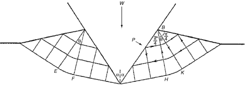
Fig. 7 Slip-line pattern for a two-dimensional wedge penetrating an ideally plastic material (Ref 18). The
pressure across the face of the indenter is uniform and has the value P = 2k(1 + θ), where θ is the angle
HBK in radians. This analysis allows for the displacement of the deformed material as can be seen in the
figure. Source: Ref 6
Equation 17a 17b is the same as Eq 12 derived for a flat punch and shows the yield pressure is again about three
times the yield stress. The two-dimensional analysis and the expression for yield pressure (P = CY) for a wedge
are expected to apply to the case of solid pyramidal and conical indenters just as the flat punch analysis was
found to hold fairly well for a flat circular punch. In fact, it has been shown experimentally that it is true.
However, the value of C for these solid indenters is found in practice to be slightly higher than for a spherical
indenter (3.2 versus 3.0), and this is considered to be probably due to the higher friction between the indenter
and the material.
The pyramidal and conical indenters may be considered to have a spherical indentation point with an extremely
small radius. The plastic deformation therefore starts immediately after the indenter comes in contact with the
material surface, even at very small loads. As the load is increased, the indentation increases in size and depth,
but its shape and the flow pattern remain unchanged whatever its depth. This implies that the indentations
produced by these indenters are geometrically similar for all indentation loads, and hence, the hardness values
measured by these indenters are, for all practical purposes, independent of the indentation load (compare this
with the case of the Brinell test where the requirement is that the d/D ratio should be constant to obtain identical
hardness values).
The preceding discussion is true for the commonly used microhardness and macrohardness tests with
indentations above a certain size where the hardness is independent of their depth. However, recent
investigations have shown that for indentations of extremely small depths (50 nm), the hardness can vary
inversely with depth due to the probable influence of several surface factors such as dislocation image forces,
contamination layers, and electric fields (Ref 19).
Rockwell Hardness Test with a Conical Indenter. In the Rockwell test, a load of 10 kg is first applied to the
material surface, and the depth of penetration is considered as zero for further depth measurements. A load of
90 or 140 kg is then applied and removed, leaving the minor load in place, and the additional depth of
penetration is measured directly on a dial gage, which gives the hardness value that may be correlated with
Vickers or Brinell values. In the Rockwell test, a spherical indenter is used for softer materials (Rockwell B
scale), and a conical indenter is used for hard materials (Rockwell C scale). Other scales of Rockwell test are
omitted from this discussion but are described in the article “Indentation Hardness Testing of Metals and
Alloys” in this Section.
Rockwell testing has two important advantages as compared to other tests previously discussed:
• Application and retention of the minor load during the test prepares the surface upon which the
incremental penetration depth due to the major load is measured.
• The hardness value is read directly on the dial gage without the necessity for measuring the indentation
dimensions, as in other hardness testing methods. This expedites the testing process—an important
advantage in manufacturing and quality control.
However, there may be appreciable elastic recovery of the material when the major load is removed, and the
recovered indentation depth will be less than the depth before removing the load. The hardness value deduced
from the depth of recovered indentation may, therefore, be in error. This error may not be serious if the
instrument is calibrated for materials having approximately the same elastic modulus, a requirement that is
generally satisfied in industry where the most common materials used in manufacturing are ferrous and have
approximately the same elastic modulus.
If the above effect is neglected and the plastic deformation is large compared to the elastic recovery, then it is
relatively simple to obtain a relationship between the hardness values obtained from depth measurements and
those from diameter measurements of the spherical indentation. Thus, assuming that the penetration depth, t, is
small as compared to the ball diameter, D, one can obtain from simple geometry considerations that t = d
2
/4D
where d is the diameter of the indentation. Since the mean pressure P across the indentation, which is
equivalent to the Meyer hardness, is given by P = 4W/πd
2
:
t = (W/P)(1/πD)
(Eq 18)
Thus, if the load is kept constant as in a Rockwell test, Eq 18 shows depth of penetration t is inversely
proportional to P; that is, the depth of penetration increases with decreasing hardness. This fact is reflected in
the dial gage readings, which do not give the actual depth of penetration but, rather, give a quantity, R, given by
100 scale divisions minus the depth penetrated. Thus:
R = constant - t
or
R = C
1
- C
2
/ P
(Eq 19)
where C
1
and C
2
are constants.
This type of relation is approximately obeyed if a spherical indenter is employed. However, a different relation
is obtained if a conical indenter is used. Thus if α is the semi-angle of the cone and the depth of penetration is t
= a cotα where 2a is the indentation diameter, then:
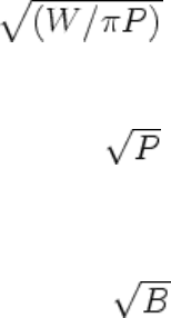
t = cotα
(Eq 20)
where P, the mean pressure, is again given by P = W/πa
2
. Since t is inversely proportional to P for a given value
of α, the Rockwell number may be expressed by the relationship:
R = C
3
- C
4
/
(Eq 21)
where C
3
and C
4
are constants. If Rockwell hardness values R
c
, obtained using a spherically tipped conical
indenter, are plotted against Brinell hardness numbers, B, it is found that the curve can be approximately
represented by the relationship:
R
c
= C
5
- C
6
/
(Eq 22)
where C
5
and C
6
are constants.
Equation 22 is similar to Eq 21 with P replaced by B. Since it is reasonable to assume Meyer hardness P is not
widely different from B, it may be concluded that the theoretical relation between R
c
and B (Eq 21) is
substantiated by the empirical observations (Eq 22), and this provides a degree of validity to the concept of
measurement of hardness from depth measurements.
Summary. The indentation hardness values are essentially a measure of the elastic limit or yield stress of the
material being tested. For most types of indenters in use, the yield pressure under conditions of appreciable
plastic flow is approximately three times the yield stress of the material. The elastic recovery of the indentation
when the load and the indenter are removed seems to affect mostly the depth of the indentation rather than the
projected area of the indentation. Consequently the yield pressure or the hardness as measured from the
indentation dimensions are nearly the same as would be obtained if measurements were made before the load
and the indenter were removed.
The yield pressure is mostly dependent on the plastic properties of the material and only to a secondary extent
on the elastic properties. If the hardness measurements are made based on the depth measurements, then the
elastic recovery may affect the calculated yield pressure, which may be in error when compared with the actual
values that may be obtained during indentation. However, this error may be small when the instrument is
calibrated for materials with similar elastic moduli.

With conical and pyramidal indenters, the indentations are geometrically similar (whatever the indentation
size), and, therefore, the mean pressure to produce the plastic flow is almost independent of the indentation
size. Consequently the hardness value is fairly constant over a wide range of loads. This means it is not
necessary in practice to specify the load.
With spherical indenters, the shape of the indentation varies with its size so that the amount of work hardening,
the elastic limit, and, as a result, the yield pressure in general increase with the size of the indentation and hence
with the load. It is therefore necessary in Brinell hardness measurements to specify the load and the diameter of
the indenter. With spherical indenters the ratio W/D
2
must be maintained constant to produce geometrically
similar indentations and nearly identical hardness numbers.
In Brinell testing, the increase in the yield pressure with the size of indentation provides useful information
about the yield stress of the material and about the way in which the yield stress increases with the amount of
deformation. In fact, the hardness measurements made using a spherical indenter can be used in conjunction
with the Meyer analysis and Meyer's index, n, to determine the work hardening coefficient, x, using the
relationship n = x + 2.
References cited in this section
6. D. Tabor, The Hardness of Metals, Clarendon Press, Oxford, 1951
7. E. Meyer, Zeits. D. Vereines Deutsch. Ingenieure, Vol 52, 1908, p 645
8. L. Prandtl, Nachr. d. Gesellschaft d. Wissensch, zu Göttingen, Math.-Phys.Klasse, 1920, p 74
9. R. Hill, The Mathematical Theory of Plasticity, Oxford, 1950, p 254
10. S. Timoshenko, Theory of Elasticity, McGraw-Hill, 1934
11. R.M. Davies, Proc. R. Soc. (London) A, Vol 197, 1949, p 416
12. Y.-T. Cheng and C.-M. Cheng, Philos. Mag. Lett., Vol 77 (No. 1), 1998, p 39–47
13. A. Bolshakov and G.M. Pharr, J. Mater. Res., Vol 13 (No. 4), April 1998, p 1049–1058
14. P. Ludwik, Die Kegelprobe, J. Springer (Berlin), 1908
15. G.A. Hankins, Proc. Inst. Mech. Eng. D, 1925
16. R. Smith and G. Sandland, Proc. Inst. Mech. Eng., Vol 1, 1922, p 623
17. S.R. Williams, Hardness and Hardness Measurements, American Society for Metals, 1942
18. R. Hill, E.H. Lee, and S.J. Tupper, Proc. R. Soc. (London) A, 1947, Vol 188, p 273
19. W.C. Oliver, R. Hutchings, and J.B. Pethica, STP 889, ASTM, 1995, p 90–108
Introduction to Hardness Testing
Gopal Revankar, Deere & Company
Classification of Hardness Tests

The hardness tests may be classified using various criteria, including type of measurement, magnitude of
indentation load, and nature of the test (i.e., static, dynamic, or scratch).
Type of Measurement. Hardness tests may be classified into two types: one, involving measurement of
dimensions of the indentation (Brinell, Vickers, Knoop) and the other, measuring the depth of indentation
(Rockwell, nanoindentation). They may also be classified as the traditional tests, which measure one contact
area or penetration depth at a prescribed load (Brinell, Vickers, Knoop, Rockwell), and the recent instrumented-
indentation tests, which allow for a continuous measurement of load and displacement.
Magnitude of Indentation Load. Hardness tests may be classified based on the magnitudes of indentation loads.
There are, thus, macrohardness, microhardness, and the relatively new nanohardness tests. For macrohardness
tests, indentation loads are 1 kgf or greater:Vickers testing may use loads from 1 to 120 kgf. Rockwell test
loads vary from 15 to 150 kgf, depending on the type of indenter and the Rockwell scale of measurement.
Brinell tests involve 500 and 3000 kgf loads though intermediate loads. Loads as low as 6.25 kgf are
occasionally used.
The microhardness tests (Vickers and Knoop) use smaller loads ranging from 1 gf to 1 kgf, the most common
being 100 to 500 gf and suited for material layers that are thicker than about 3 mm. The nanoindentation test,
also called the instrumented indentation test, depends on the simultaneous measurement of the load and depth
of indentation produced by loads that may be as small as 0.1mN, with depth measurements in the 20 nm range.
Static, Dynamic, or Scratch Types. All of the above mentioned tests are of the static type. In the dynamic tests,
the indenter, usually spherical or conical, is allowed to bounce off the surface of the material to be tested, and
the rebound height of the indenter is used as a measure of hardness. The scleroscope is the most popular test of
this type. In the scratch test, a material of known hardness is used to scratch the surface of material of unknown
hardness to determine if the latter is more or less hard than the reference material.
Eddy current hardness testing, which does not fall into any of the above categories, is a noncontact method and
does not use an indenter. The method depends on the measurement of eddy current permeability of the material
surface layer, which is determined by its microstructure and hence hardness.
These and various other test methods are discussed in greater detail in the subsequent articles of this Section.
Introduction to Hardness Testing
Gopal Revankar, Deere & Company
Acknowledgments
Substantial portions of this brief review are adaptations from the classic work of Tabor on hardness (Ref 6).
The author is indebted to the continued usefulness of that book.
Reference cited in this section
6. D. Tabor, The Hardness of Metals, Clarendon Press, Oxford, 1951
Introduction to Hardness Testing
Gopal Revankar, Deere & Company
References
1. R.W. Rice, The Compressive Strength of Ceramics in Materials Science Research, Vol 5, Ceramics in
Severe Environments, W.W. Kriegel and H. Palmour III, Ed., Plenum, 1971, p 195–229

2. J.A. Brinell, II Cong. Int. Méthodes d' Essai (Paris), 1900
3. M.O. Lai and K.B. Lim, J. of Mater. Sci., Vol 26 (1991), p 2031–2036
4. S.C. Chang, M.T. Jahn, C.M. Wan, J.Y.M. Wan, and T.K. Hsu, J. Mater. Sci., Vol 11, 1976, p 623
5. W. Kohlhöfer and R.K. Penny, Int. J. Pressure Vessels Piping, Vol 61, 1995, p 65–75
6. D. Tabor, The Hardness of Metals, Clarendon Press, Oxford, 1951
7. E. Meyer, Zeits. D. Vereines Deutsch. Ingenieure, Vol 52, 1908, p 645
8. L. Prandtl, Nachr. d. Gesellschaft d. Wissensch, zu Göttingen, Math.-Phys.Klasse, 1920, p 74
9. R. Hill, The Mathematical Theory of Plasticity, Oxford, 1950, p 254
10. S. Timoshenko, Theory of Elasticity, McGraw-Hill, 1934
11. R.M. Davies, Proc. R. Soc. (London) A, Vol 197, 1949, p 416
12. Y.-T. Cheng and C.-M. Cheng, Philos. Mag. Lett., Vol 77 (No. 1), 1998, p 39–47
13. A. Bolshakov and G.M. Pharr, J. Mater. Res., Vol 13 (No. 4), April 1998, p 1049–1058
14. P. Ludwik, Die Kegelprobe, J. Springer (Berlin), 1908
15. G.A. Hankins, Proc. Inst. Mech. Eng. D, 1925
16. R. Smith and G. Sandland, Proc. Inst. Mech. Eng., Vol 1, 1922, p 623
17. S.R. Williams, Hardness and Hardness Measurements, American Society for Metals, 1942
18. R. Hill, E.H. Lee, and S.J. Tupper, Proc. R. Soc. (London) A, 1947, Vol 188, p 273
19. W.C. Oliver, R. Hutchings, and J.B. Pethica, STP 889, ASTM, 1995, p 90–108
Macroindentation Hardness Testing
Edward L. Tobolski, Wilson Instruments Division, Instron Corporation; Andrew Fee, Consultant
Introduction
ALMOST ALL indentation hardness testing is done with Brinell, Rockwell, Vickers, and Knoop indenters.
These modern methods of indentation testing began with the Brinell test, which was developed around 1900
when the manufacturing of ball bearings prompted J.A. Brinell in Sweden to use them as indenters. The Brinell
test was quickly adopted as an industrial test method soon after its introduction, but several limitations also
became apparent. Basic limitations included test duration, the large size of the impressions from the indent, and
the fact that high-hardness steels could not be tested with the Brinell method of the early 1900s.
The limitations of the indentation test developed by Brinell prompted the development of other
macroindentation hardness tests, such as the Vickers test introduced by R. Smith and G. Sandland in 1925, and
the Rockwell test invented by Stanley P. Rockwell in 1919. The Vickers hardness test follows the same

principle of the Brinell test—that is, an indenter of definite shape is pressed into the material to be tested, the
load removed, the diagonals of the resulting indentation measured, and the hardness number calculated by
dividing the load by the surface area of indentation. The principal difference is that the Vickers test uses a
pyramid-shaped diamond indenter that allows testing of harder materials, such as high-strength steels.
The Rockwell hardness test differs from Brinell hardness testing in that the hardness is determined by the depth
of indentation made by a constant load impressed upon an indenter. Rockwell hardness testing is the most
widely used method for determining hardness, primarily because the Rockwell test is fast, simple to perform,
and does not require highly skilled operators. By use of different loads (force) and indenters, Rockwell hardness
testing can determine the hardness of most metals and alloys, ranging from the softest bearing materials to the
hardest steels.
This article describes the principal methods for macroindentation hardness testings by the Brinell, Vickers, and
Rockwell methods. Microindentation hardness tests with the Knoop and Vickers indenters are described further
in the next article “Microindentation Hardness Testing.” An overall discussion on the applications and selection
of these test methods is provided in the article “Selection and Industrial Applications of Hardness Tests” in this
Volume.
Macroindentation Hardness Testing
Edward L. Tobolski, Wilson Instruments Division, Instron Corporation; Andrew Fee, Consultant
Rockwell Hardness Testing
The Rockwell hardness test is defined in ASTM E 18 and several other standards (Table 1). Rockwell hardness
testing differs from Brinell testing in that the Rockwell hardness number is based on the difference of indenter
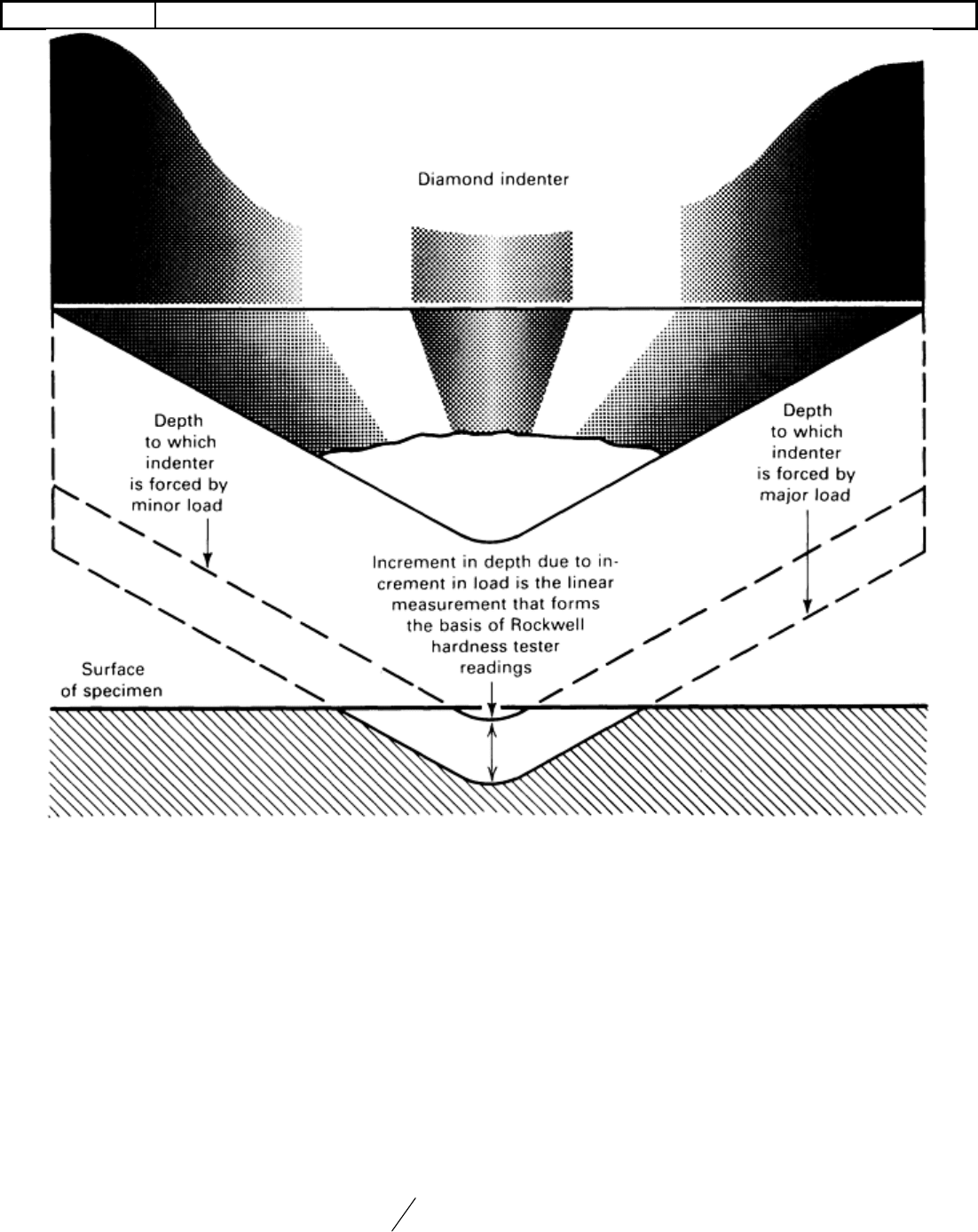
depth from two load applications (Fig. 1). Initially a minor load is applied, and a zero datum is established. A
major load is then applied for a specified period of time, causing an additional penetration depth beyond the
zero datum point previously established by the minor load. After the specified dwell time for the major load, it
is removed while still keeping the minor load applied. The resulting Rockwell number represents the difference
in depth from the zero datum position as a result of the application of the major load. The entire procedure
requires only 5 to 10 s.
Table 1 Selected Rockwell hardness test standards for metals and hardmetals
Standard No. Title
ASTM B 294 Standard Test Method for Hardness Testing of Cemented Carbides
ASTM E 18 Test Methods for Hardness and Rockwell Superficial Hardness of Metallic Materials
ASTM E 1842 Test Method for Macro-Rockwell Hardness Testing of Metallic Materials
BS 5600-4.5 Powder Metallurgical Materials and Products—Methods of Testing and Chemical Analysis of
Hardmetals—Rockwell Hardness Test (Scale A)
BS EN ISO
6508-1
Metallic Materials—Rockwell Hardness Test—Part 1: Test Method (Scales A, B, C, D, E, F,
G, H, K, N, T)
BS EN ISO
6508-2
Metallic Materials—Rockwell Hardness Test—Part 2: Verification and Calibration of Testing
Machines (Scales A, B, C, D, E, F, G, H, K, N, T)
BS EN ISO
6508-3
Metallic Materials—Rockwell Hardness Test—Part 3: Calibration of Reference Blocks
(Scales A, B, C, D, E, F, G, H, K, N, T)
ISO 3738-1 Hardmetals—Rockwell Hardness Test (Scale A)—Part 1: Test Method
ISO 3738-2 Hardmetals—Rockwell Hardness Test (Scale A)—Part 2: Preparation and Calibration of
Standard Test Blocks
JIS B 7726 Rockwell Hardness Test—Verification of Testing Machines
JIS B 7730 Rockwell Hardness Test—Calibration of Reference Blocks
JIS Z 2245 Method of Rockwell and Rockwell Superficial Hardness Test
Fig. 1 Principle of the Rockwell test. Although a diamond indenter is illustrated, the same principle
applies for steel ball indenters and other loads.
Use of a minor load greatly increases the accuracy of this type of test, because it eliminates the effect of
backlash in the measuring system and causes the indenter to break through slight surface roughness. The basic
principle involving minor and major loads is shown in Fig. 1. Although the principle is illustrated with a
diamond indenter, the same principle applies for hardened steel ball indenters and other loads.
Test Types and Indenters
There are two types of Rockwell tests: Rockwell and superficial Rockwell. In Rockwell testing, the minor load
is 10 kgf, and the major load is 60, 100, or 150 kgf. In superficial Rockwell testing, the minor load is 3 kgf, and
major loads are 15, 30, or 45 kgf. In both tests, the indenter may be either a diamond cone or a hardened ball
depending principally on the characteristics of the material being tested.
Hardened ball indenters with diameters of
1
16
, ⅛ , ¼ and, ½in. (1.588, 3.175, 6.35, and 12.7 mm) are used
for testing softer materials such as fully annealed steels, softer grades of cast irons, and a wide variety of
nonferrous metals. Hardened steel balls have traditionally been used for Rockwell testing. However, a
changeover to tungsten carbide is in process. All future testing will be done with carbide balls. This will
improve the durability of the balls significantly, but a slight change in hardness results may occur.
