ASM Metals HandBook Vol. 17 - Nondestructive Evaluation and Quality Control
Подождите немного. Документ загружается.

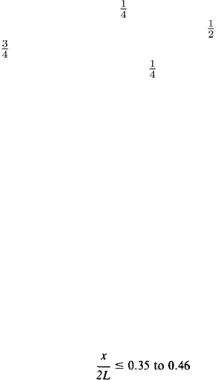
For control of image quality, standard ASTM penetrameters were used. The penetrameter for view A was 2 mm (0.08 in.)
thick and was placed on a 110 mm (4 in.) thick block adjacent to the impeller. Four penetrameters were used for view
B: a 0.25 mm (0.010 in.) thick penetrameter on a 13 mm ( in.) thick block, a 0.38 mm (0.015 in.) thick penetrameter on
a 20 mm ( in.) thick block, a 0.5 mm (0.020 in.) thick penetrameter on a 25 mm (1 in.) thick block, and a 1.15 mm
(0.045 in.) thick penetrameter on a 57 mm (2 in.) thick block. For view C, a 0.38 mm (0.015 in.) thick penetrameter was
placed directly on the part. All penetrameters and blocks were made of austenitic stainless steel.
This procedure gave both the required complete coverage and the specified 2-2T image quality. Castings were routinely
inspected to a minimum quality level corresponding to severity level 1 (in ASTM E 186) in the hub area and to severity
level 2 to 3 (in ASTM E 446) in the shroud area.
Inspection of Weldments
The radiographic inspection of weldments is usually intended to cover only welds and heat-affected zones. The quality of
the base metal beyond the heat-affected zones is seldom of interest at this stage of inspection. Therefore, the viewing
direction is usually selected to reveal clearly the features of welds and heat-affected zones, regardless of the overall shape
of the weldment. See the article "Weldments, Brazed Assemblies, and Soldered Joints" in this Volume for further
information on the NDE of welds.
Arc Welds. Generally, arc-welded joints are radiographed using a viewing direction normal to the surface of the weld.
For butt joints, this view directs the central beam perpendicular to the surfaces of the adjacent plates, but for other types
of joints such as T-joints and lap joints, the central beam is usually inclined to both adjacent legs. The maximum area of
coverage for a single radiograph is normally recommended to be no more than would result in a 6 to 10% difference in
penetrated thickness between the center of the area and the extremities. Mathematically, this can be expressed for flat
plates of uniform thickness as:
(Eq 19)
where x is the field size, L is the source-to detector distance, and the values 0.35 and 0.46 are derived from the laws of
similar triangles for 6 and 10% increase in penetrated thickness, respectively. The numerical range in Eq 19 is equivalent
to a radiation-beam cone angle of about 39 to 49°. This range is not intended to limit the thickness range inspected in a
single radiograph but rather to ensure the detection of transverse cracklike discontinuities by keeping the image relatively
sharp and undistorted.
Views normal to the surface of the weld are not always satisfactory. Flaws in a weld such as dense inclusions due to the
deposition of metal from a tungsten electrode, excessive segregation in light alloys, porosity, and shrinkage can be
revealed regardless of view. However, cracks or nonfusion along the edge of the fusion zone can be best revealed when
the viewing direction is parallel to the face of the joint. The detection of centerline cracks or incomplete penetration
requires a normal view. Only square-groove butt joints, U-groove joints, and J-groove joints can be satisfactorily
inspected with a normal view; other types of joints, including V-groove joints, bevel joints, flare joints, and fillets, require
two views, one parallel to each original prepared edge, for correct inspection for cracks or regions of incomplete fusion.
Certain flaws cannot be detected at all because they lie along planes that are more or less parallel to the weld surface. The
shape of most weldments prohibits selection of a viewing direction parallel to the weld surface, which is the most
favorable view for detecting underbead cracking or delamination. (Ultrasonic inspection is a much more suitable method
for detecting either underbead cracking or delamination.)
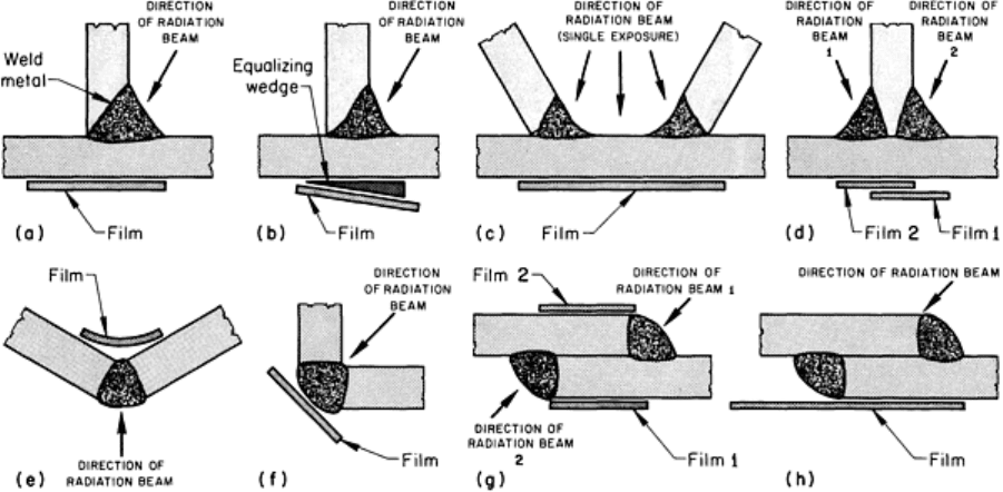
The most favorable view for fillet welds is a direction that roughly bisects the angle between the legs of the section.
Preferred arrangements for several types of fillet welds are shown in Fig. 49. Single-fillet T-joints can be inspected with
the simple arrangement shown in Fig. 49(a) or with an arrangement incorporating an equalizing wedge (Fig. 49b) to
reduce the inherent subject contrast caused by variations in penetrated thickness across the weld zone. The arrangement in
Fig. 49(b) is more relevant for film radiography than for real-time radiography because image processing can be used in
real-time radiography. In film radiography, the high subject contrast can result in overexposure of the thin section on one
side of the weld or in underexposure of both the weld and thick sections. Either underexposure or overexposure reduces
sensitivity and may not resolve images of flaws having low subject contrast. An equalizing wedge is most effective when
the size of the fillet weld exceeds the thickness of the thin section. The technique is mainly used on straight seams;
special-shape wedges would be required for other seam shapes.
Fig. 49 Preferred viewing directions for the radiographic inspection of several types of fillet-
welded joints. (a)
Single-fillet T-joint. (b) Single-fillet T-joint with equalizing wedge. (c) Two adjacent single-
fillet joints
radiographed simultaneously. (d) Double-fillet T-
joint. (e) Corner joint with film positioned at the inside surface.
(f) Corner joint with film positioned at the outside surface. (g) and (h) Alternative views for double-
welded lap
joint
Occasionally, the shape of the weldment is such that two or more seams can be inspected with a single exposure in film
radiography (Fig. 49c). The savings in time and material often justify selection of a single view whose area of coverage
encompasses two or more seams. However, if the shape of the seam is such that a single view would give severely
reduced sensitivity, multiple views should be specified on the radiographic standard shooting sketch.
T-joints that are welded on both sides usually cannot be inspected satisfactorily with a single radiographic view or
exposure. Two radiographs, one for each fillet (Fig. 49d), are needed. Corner welds can be inspected from either side,
depending on which side provides access (Fig. 49e and f). Lap joints can be inspected using multiple views or by a single
view, as shown in Fig. 49(g) and 49(h). The main factor that determines which technique is most appropriate is the
amount of separation between welds in a double-welded joint. When multiple views are used, the central beam of
radiation should be aligned with the weld for each view, as in Fig. 49(g). When a single view is used, the central beam
should be aligned with a spot midway between the welds, as in Fig. 49(h). Only a single radiograph is needed for each
weld segment in a single-welded lap joint.
The techniques discussed above, particularly those for the inspection of fillet welds, are also appropriate for the inspection
of junction areas of castings, forgings, and formed parts. Circumferential welds, which are one of the more usual types of
arc welds inspected by radiography, can be inspected with techniques discussed in the section "Inspection of Tubular
Sections" in this article.
Resistance welds, mainly spot welds and seam welds, are used to join relatively thin sheets. Most often, a resistance-
welded joint can be considered a type of lap joint, with the weld positioned inboard of the overlapping edge. Usually, the
only outward sign of weld position is a slight depression on the surface of the workpiece resulting from electrode pressure
applied during welding.
In the radiography of spot welds and seam welds, the central beam is ordinarily directed normal to the surface of one of
the sheets and is centered on the depression that indicates the location of the weld. Radiography can detect discontinuities
in both weld metal and base metal, including cracks, inclusions and porosity in the weld, cracking and deformation in the

base metal, segregation in the fusion zone of resistance welds in light alloys, and expulsion of molten metal between the
faying surfaces. Normally, deficiencies such as underbead cracking and incomplete fusion are not revealed by
radiography, although incomplete fusion can sometimes be inferred from the presence of other discontinuities. The area
of coverage should be limited in a manner similar to that suggested for arc welds so that maximum sensitivity to cracklike
discontinuities can be maintained.
A view other than the normal view is sometimes dictated by the shape of the weldment, especially when portions of the
weldment may cast shadows that would detract from the clarity of the weld-zone image. Even in such cases, it is best to
select a view as near to normal as possible so as to minimize distortion. In contrast to arc welds, in which an oblique view
adversely affects both the intensity of the transmitted radiation and the sensitivity, only sensitivity is affected to any great
degree by using an oblique view for the inspection of resistance welds. Most resistance-welded assemblies are thin
enough that the section can be penetrated by relatively low-energy radiation even with oblique views. The sensitivity,
expressed as minimum detectable discontinuity size, varies with the cosecant of the angle between the viewing direction
and the sheet surface. This relationship indicates that the smallest value of minimum detectable discontinuity size occurs
with a 90° viewing direction, and viewing directions between 90° and 65° give no more than about a 10% increase in this
value. The main disadvantage of oblique views is their inability to resolve the images of transverse cracks (through-
thickness cracks) in either the weld or adjacent heat-affected zones.
Inspection of Tubular Sections
Although film radiography is not well suited to the inspection of continuously produced tubular products such as tubing
and pipe, the method is suited to the inspection of tubular sections in a wide variety of products and assemblies. Real-time
radiography, on the other hand, is more suited to the inspection of continuously produced tubular products, but not tubular
sections in large, complex assemblies.
Radiography is the method most often specified for the inspection of welded joints between tubes or pipes or between a
tube and a pressure vessel when the weldment is manufactured to ASME Boiler and Pressure Vessel Code specifications.
Other hollow sections such as cylindrical bosses on castings and forgings, brazed tube-and-socket joints, large-diameter
transmission pipe (line pipe), and longitudinally welded square or circular structural tubing, are frequently inspected by
radiography. There are three major inspection techniques for tubular sections:
• The double-wall, double-image technique
• The double-wall, single-image technique
• The single-wall, single-image technique
The double-wall, double-image technique is mainly applicable to sections with an outside diameter of no more
than 90 mm (3 in.). This technique produces a radiograph in which the images of both walls of a tubular section are
superimposed on one another. The beam of radiation is directed toward one side of the section, and the radiation
conversion medium surface is placed on the opposide side, usually tangent to the section.
As shown in Fig. 50(a), two radiographs 90° apart are required to provide complete coverage when the ratio of outside
diameter to inside diameter is 1.4 or less. In exposure 1 in Fig. 50(a), the area between the phantom lines is recorded as a
through-thickness image, and the area outside the lines is recorded essentially as an image in the plane of the tube wall
that exhibits too much subject contrast for meaningful interpretation. In exposure 2, the area outside the lines in exposure
1 is recorded as a through-thickness image, and there is a certain amount of overlap between the through-thickness images
of exposures 1 and 2, which is shown as darker shading in exposure 2 in Fig. 50(a).
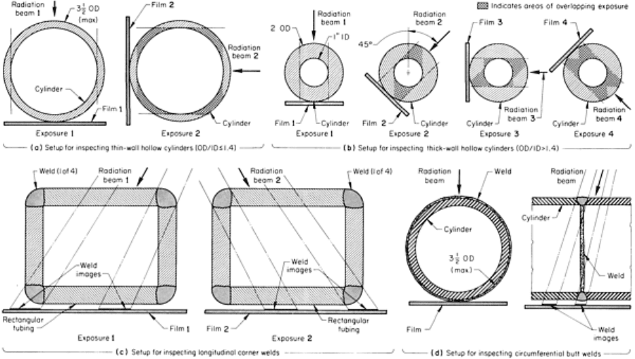
Fig. 50 Diagrams illustrating the relation of radiation beam, testpiece, and film for the double-wall, double-
image technique of inspecting hollow cylinders or welds in tubular sections. Dimensions given in inches
When the ratio of outside diameter to inside diameter is greater than 1.4--that is, when radiographing a thick-wall tube--
the number of views required to provide complete coverage can be determined by multiplying that ratio by 1.7 and
rounding off to the next higher integer. For example, to examine a 50 mm (2 in.) OD cylinder with a 25 mm (1 in.) diam
axial hole, a total of 1.7 × 2 = 3.4, or 4 views, will provide complete coverage. The circumferential displacement between
each view is found by dividing 180° by the number of shots. In this case, 180°/4, or 45°, rotation of the cylinder with
respect to the viewing direction is required between exposures, as shown in Fig. 50(b) The area within the phantom lines
for each exposure in Fig. 50(b) indicates the region of a 50 mm (2 in.) OD cylinder with a 25 mm (1 in.) diam axial hole
that is recorded as a through-thickness image; heavy shading indicates regions recorded as a through-thickness image on
preceding views. If only three shots are used for a cylinder with a 2:1 ratio of outside to inside diameters, there is only a
minimal amount of overlap between shots, inadequate to ensure that all detectable discontinuities in the regions of overlap
will be recorded.
When an odd number of views are required for complete coverage, the angular spacing between shots can be determined
by dividing 360° by the number of views as an alternative to dividing 180° by the number. This alternative cannot be used
when the number of views is even, because half of the resulting radiographs would be mirror images of the remaining
radiographs and sections of the outside circumference would not receive adequate coverage.
The double-wall, double-image technique can be applied to the inspection of diagonally opposite corner welds in a
section of rectangular structural tubing constructed by welding four pieces of metal strip together to form a box section.
Only two views are required for the inspection of all four longitudinal welds, as shown in Fig. 50(c). As with circular
sections, hollow box sections can be inspected by the double-wall, double-image technique only when they are small; that
is, when section height in direction or selected view is 100 mm (4 in.) or less.
A variation of the double-wall, double-image technique, sometimes called the corona or offset technique, is often used for
the inspection of circumferential butt welds in small-diameter tubing and pipe. In the corona technique, the central beam
is directed at an acute angle to the run of the tube (Fig. 50d) so that the weld is projected on the film as an ellipse rather
than a straight band. The offset angle of the radiation beam shown in Fig. 50(d) must be large enough that the image of
the upper section of the weld zone does not overlap the image of the lower portion, but not so large as to introduce an
unnecessary degree of distortion. Also, the larger the offset angle, the greater the probability that the technique will fail to
detect incomplete fusion at the root of the plain butt weld. Incomplete fusion at the root can have the radiographic
appearance of a root void, but if it exists in a tightly butted joint or if the root gap is filled by capillary action of the
molten weld metal, incomplete fusion has the appearance of a cracklike discontinuity lying in the plane of the joint. The
incident radiation must be parallel to the plane of the joint so as to detect incomplete root fusion in a tight joint.
The correct number of views and the circumferential location of corresponding views can be determined for the corona
technique in the same manner as for the basic double-wall, double-image technique. Sometimes, as when a weld must be
inspected for both radial cracks and internal voids, it is beneficial to use both the basic technique and the corona
technique--the former to detect cracks and the latter to locate voids.
In all variations of the double-wall, double-image technique, the image of the section of the cylinder wall that is closest to
the radiation source will exhibit the greatest amount of enlargement, the greatest degree of shape distortion, and the
greatest degree of unsharpness. Selection of proper source-to-detector distance should be based on obtaining the specified
image quality for that section of the cylinder. Also, penetrameters should be located where they will evaluate the image of
the section closest to the source.
The double-wall, single-image technique is mainly applicable to hollow cylinders and tubular sections exceeding
90 mm (3 in.) in outside diameter. This technique produces a radiographic image of only the section of the wall that is
closest to the imaging plane, although the radiation penetrates both walls. The source is positioned relatively close to the
section, so that blurring caused by geometric unsharpness in the image of the cylinder wall closest to the source makes the
image completely indistinguishable. Only the image of the wall section closest to the detector is sharply defined.
In film (or paper) radiography, exposures are calculated on the basis of double the wall thickness of the hollow section, as
they are for the double-wall, double-image technique. The area of coverage is limited by geometric unsharpness and
distortion at the extremities of the resolved image for hollow cylinders that are less than about 380 mm (15 in.) in outside
diameter. For larger cylinders, film size is the usual limiting factor. Usually, at least five separate exposures equally
spaced around the circumference are required for complete coverage. There must be enough overlap between adjacent
exposures to ensure that all of the outside circumference is clearly recorded.
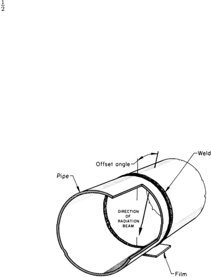
The radiation is usually directed normal to the surface of the cylinder. However, in some cases, it may be advantageous to
use viewing direction similar to that of a corona exposure. For example, if a circumferential weld has a high and irregular
crown, it may be desirable to have the radiation that impinges on the area of the weld being inspected pass through the
tube wall adjacent to the weld so that the incident radiation is attenuated by a more uniform and thinner section, as shown
in Fig. 51.
Fig. 51 Schematic of the double-wall, single-
image inspection technique applied to a circumferential butt weld
in a large-diameter pipe showing relation of radiation beam, weld, and film
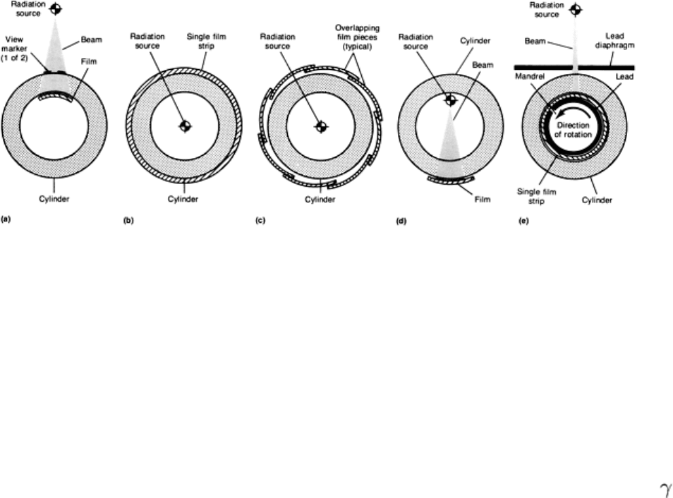
The single-wall, single-image technique is an alternative to either of the double-wall techniques and can be used
only when the interior of a section is accessible. With this technique, the radiation source can be placed outside the
cylinder and the radiation detector inside the cavity (Fig. 52a), or the detector can be placed outside the cylinder and the
radiation source inside (Fig. 52b). In both setups, only a single wall is radiographed. A significant advantage of the single-
wall technique is that it is more sensitive than double-wall techniques because any flaw that may be present occupies a
greater percentage of the penetrated thickness.
Fig. 52
Schematic of techniques employing different arrangements of radiation source, cylinder, and film for
the single-wall, single-image radiography of cylindrical sections using external and internal radiatio
n sources.
See text for discussion.
When using the technique shown in Fig. 52(a), the cylinder is rotated to generate a series of radiographs. In film
radiography, the amount of rotation must be controlled so that successive radiographs contain regions of overlap. The
correct amount of overlap can be proved by placing lead view markers on the surface that is remote from the film; if the
image of a view marker appears in both adjacent radiographs, complete coverage is ensured.
In the technique shown in Fig. 52(b), the radiation source is placed inside the cylinder, and one continuous piece of film is
wrapped around the outside of the cylinder. Alternatively, several overlapping pieces can be used, as shown in Fig. 52(c).
The radiation source, which is usually either a rod-anode type of x-ray tube having 360° radiation emission or a -ray
source, is placed on the central axis of the hollow cylinder. The entire circumference is inspected with one exposure,
regardless of whether a single strip of film or several overlapping pieces are used.
Special adaptations of these techniques can be used. For example, when maximum sensitivity is required for the technique
in Fig. 52(b), the radiation source can be moved to a position close to the inside surface of the cylinder diametrically
opposite a single piece of film, as illustrated in Fig. 52(d). This adaptation can almost double the source-to-film distance,
thus reducing geometric unsharpness by almost 50%. Although there is a gain in sensitivity, there is a loss in efficiency
because the entire circumference can no longer be inspected by a single exposure. Several exposures must be made, with
the radiation source and film repositioned to several points equally spaced around the circumference to obtain complete
coverage.
Another special adaptation is shown in Fig. 52(e). In this arrangement, a continuous piece of film is placed in contact with
the inside surface of the cylinder. The film is held in place by a close-fitting, lead-covered mandrel. Incident radiation is
directed through a slit in a lead diaphragm to impinge on a narrow section of the circumference of the cylinder. The
cylinder, film, and mandrel are rotated slowly past the slit one or more times, so that the total time that a given point on
the cylinder is in front of the slit equals the required exposure time. Radiographs produced in this manner are remarkably
clear and distinct compared to other single-wall or double-wall techniques. Because the radiation beam impinges on only
a narrow region of the cylinder and because the film is in contact with the inner surface, both geometric unsharpness and
variations in transmitted intensity caused by variations in penetrated thickness are minimized. As a result, the subject
contrast and definition of internal flaws are maximum. The technique shown in Fig. 52(e) is a form of in-motion
radiography.
In-Motion Radiography
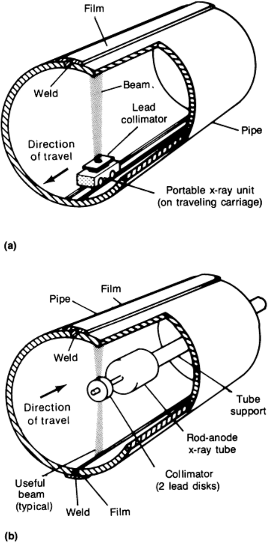
In-motion radiography is useful when large areas must be inspected. Generally, real-time radiography is more suitable for
in-motion radiography because a detector can be used to scan the test area during motion. Nevertheless, in-motion film
radiography can be used to inspect longitudinal welds in very large pipe, such as line pipe. In one method, a portable x-
ray unit is attached to a traveling carriage inside the pipe and is positioned so that a narrowly collimated x-ray beam
impinges on the weld, as shown in Fig. 53(a). The carriage moves slowly along the pipe, successively exposing a series of
films placed along the outside surface over the weld. The correct rate of travel is equal to the width of the beam in the
direction of relative motion divided by the required exposure time.
Fig. 53 Arrangements for the in-motion single-wall, single-
image film radiography of longitudinal welds in line
pipe, using (a) a conventional portable x-ray unit and (b) a rod-anode x-ray tube
An alternative setup for in-motion film radiography, in which a rod-anode x-ray tube is substituted for the portable x-ray
unit, is shown in Fig. 53(b). The principle of operation is the same; only the x-ray equipment and method of travel are
different. This setup is particularly advantageous when two or more welded joints are to be radiographed because the
joints can be radiographed simultaneously. With a rod-anode tube, radiation is emitted 360° around the axis of the tube.
As long as the center of the target is maintained on the axis of the pipe, the disk of radiation that emerges between the two
lead disks that act as a collimator will produce equal nominal film densities on all radiographs. Even with the portable x-
ray unit illustrated in Fig. 53(a), the source-to-film distance must be kept constant because if the distance is permitted to
vary there will be a gradual change in nominal film density from radiograph to radiograph as the radiation source moves
along the pipe.
The principal advantage of in-motion radiography is that less time is needed for setup and operation. The inspection of
long welds by conventional methods requires frequent repositioning of the testpiece with respect to the source and film;
consequently, there is a considerable amount of time spent in setting up for successive exposures. With in-motion
radiography, a much smaller proportion of total inspection time is required for setup. Therefore, in-motion radiography is
seldom, if ever, accomplished with a radioactive source.
Techniques similar to those described above for radiographing longitudinal welds in large-diameter pipe can also be
adapted for other product forms when radiographic inspection is to be applied to long testpieces. Also, it may be desirable
to adapt in-motion radiography for the inspection of relatively small parts, especially when the diverging beam used in
normal radiography would cause unacceptable distortion at the edges of the radiograph.
In general, a real-time radiographic technique is preferred for in-motion radiography. However, if only film techniques
are available, then in-motion radiography would be considered whenever more than four to six shots are required for
complete coverage of a long straight or circumferential weld in a relatively thin section. It is essential that the source
move at constant speed in film radiography because any variations in speed will produce parallel bands of overexposure
and underexposure in the radiograph, oriented at right angles to the direction of relative motion.
Motion Unsharpness. The real-time and film techniques used for in-motion radiography cause a specific type of
unsharpness called motion unsharpness. Any amount of relative motion of source or testpiece with respect to the image
conversion plane results in blurring of the image; the greater the amount of motion, the greater the blurring. In
conventional still radiography, it is considered good practice to eliminate all sources of motion, even vibrations, so that
motion unsharpness does not detract from radiographic quality. The amount of unsharpness caused by relative motion of
the source with respect to the testpiece and detector in in-motion radiography can be evaluated from characteristics of the
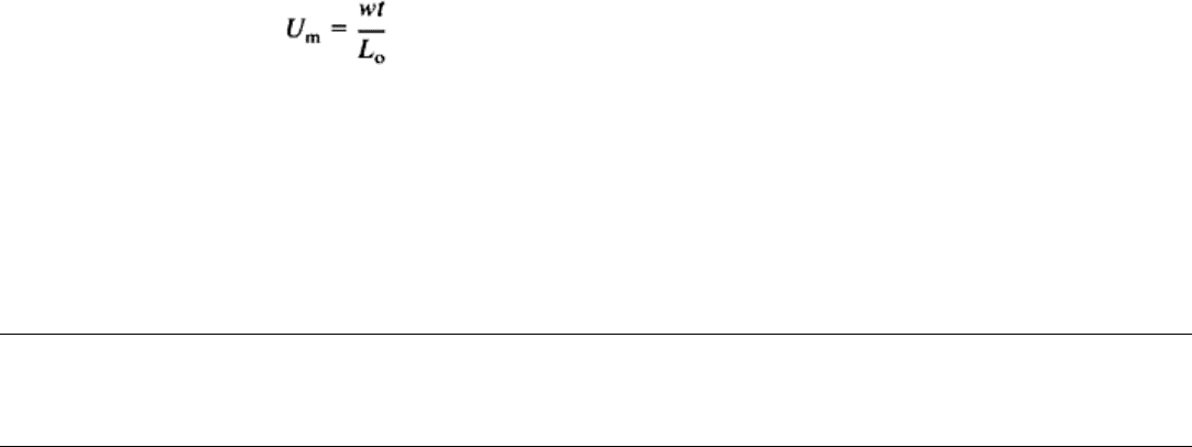
setup, much as geometric unsharpness is evaluated for conventional techniques. Motion unsharpness, U
m
, is described by:
(Eq 20)
where w is the width of the radiation beam in the direction of motion, t is the penetrated thickness, and L
o
is the source-to-
object distance.
Motion unsharpness is generally greater for in-motion radiography than geometric unsharpness for an equivalent
conventional technique. This limits the use of in-motion techniques to thin testpieces or to situations in which a long
source-to-detector distance can be used. It is essential that there be no relative movement between testpiece and detector,
so that only the movement of the source contributes to motion unsharpness.
Radiographic Inspection
Revised by the ASM Committee on Radiographic Inspection
*
Identification Markers and Penetrameters (Image-Quality Indicators)
It is important to relate a particular radiographic image to the direction of the radiation beam used to generate that image.
Furthermore, it is important that any permanent record of inspection be traceable to the particular testpiece that was
inspected or to the production lot represented by that testpiece. Identification markers are used for these purposes.
In addition to identification, the image should contain some means of evaluating the radiographic procedure in terms of its
sensitivity to test conditions. This sensitivity, known as image quality, bears directly on the ability of the radiographic
process to record images of small flaws and is usually determined by the use of penetrameters, which are also called
image-quality indicators.
Identification Markers
Identification markers are made of lead or lead alloy and are usually in the form of a coded series of letters and numbers.
The markers are placed on the testpiece or on the film adjacent to the testpiece during setup. When the testpiece is
radiographed, a distinct, clear image of the radiographically dense identification markers is produced at the same time.
Identification markers must be located so that their projected shadows do not coincide with the shadows of any regions
being inspected in the testpiece. Because markers are radiographically dense, their images will obscure any coinciding
image of the testpiece.
Both view identification and testpiece identification almost always appear in coded form. View identification is usually a
simple code (such as A, B, C, or 1, 2, 3) that relates some inherent feature of the testpiece or some specific location on the
testpiece to the view used; the term sequence numbering, which is used in some specifications, refers to view
identification. Often, the location of view markers is handwritten in chalk or crayon directly on the testpiece so that the
radiographic image can be correlated with the testpiece itself during interpretation and evaluation of the radiograph.
Sometimes, the locations of markers are steel-stamped on the surface of the part being radiographed and become a
permanent reference. It is advisable always to mark the location of view markers because it may be necessary to recheck
the setup procedure against specifications. Although the specific location of view markers is largely a matter of personal
preference, several suggested arrangements are discussed in this section. It is required only that the markers be placed so
that their images on the radiograph are legible and do not obscure any area being inspected.
View markers need not be different if identical viewing directions are used for radiographing a series of testpieces of the
same type and size. Actually, it is much simpler to begin at the letter "A" or the number "1" for view identification on
each individual testpiece. Most radiographers adopt standard methods of identifying views and indicate the type of view
markers to be used on the specification sheet for the radiographic procedure, which is commonly called a radiographic
standard shooting sketch.
The code for identification of the testpiece is usually more complex than the code used for identification of viewing
direction. Each radiographic laboratory must adopt a system of identification that is suited to its specific requirements. As
a minimum requirement, the identification code must enable each radiograph to be traced to a particular testpiece or
section of a testpiece. Identification codes can be based on part number, lot number, inspection date, customer code, or
manufacturing code; or they can be merely a series of consecutive multiple-digit numbers, with the pertinent data
concerning testpiece identification recorded in a logbook opposite the corresponding testpiece number.
Penetrameters
Penetrameters, or image-quality indicators, are of known size and shape and have the same attenuation characteristics as
the material in the testpiece. They are placed on the testpiece or on a block of identical material during setup and are
radiographed at the same time as the testpiece. Penetrameters are preferably located in regions of maximum testpiece
thickness and greatest testpiece-to-detector distance and near the outer edge of the central beam of radiation. Because of
this location, the degree to which features of the penetrameter are visible in the developed image is a measure of the
quality of that image. The image of the penetrameter that appears on the finished radiograph is evaluated during
interpretation to ensure that the desired sensitivity, definition, and contrast have been achieved in the developed image.
Penetrameters of different designs have been developed by various standards-making organizations; several of the
standard designs most widely used are shown in Fig. 54. Regardless of the design, all penetrameters have the following in
common:
•
Material used for penetrameters is the same as that of the testpiece or has the same absorption
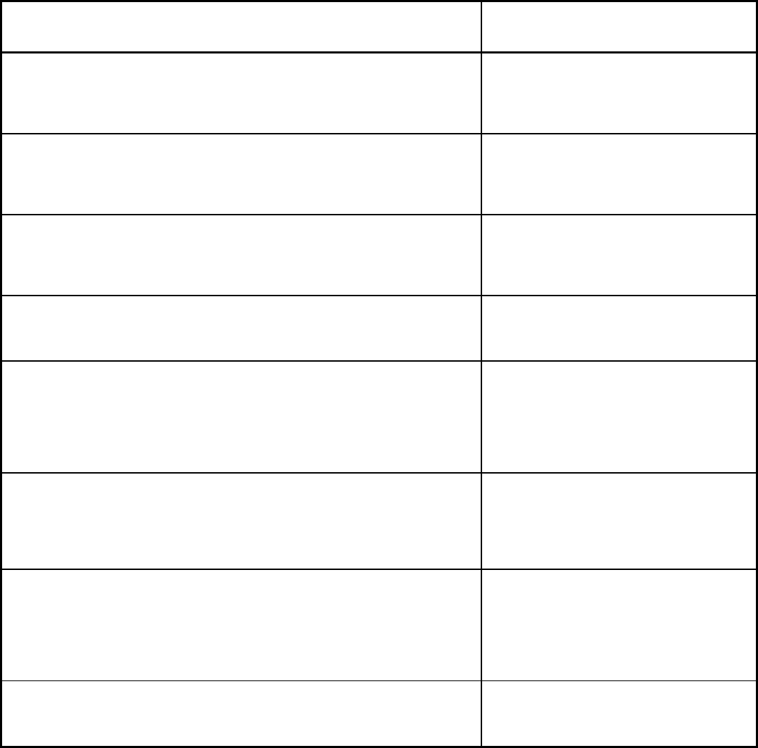
characteristics. Suitable penetrameter materials for various metalli
c testpieces are grouped in ASTM E
1025 and E 142 as shown in Table 8
• In use, the penetrameter is normally placed dir
ectly on the surface of the testpiece that faces the source.
Alternatively, when the testpiece is small or when its shape is unfavorable, the penetrameter is placed on
a block or shim of the same nominal composition and thickness as the testpiece, with the
upper surface
of the block at the same distance from the recording plane as the upper surface of the testpiece. In pipe
radiography, when permitted by specification, the penetrameter can be placed on the surface of the pipe
that faces the film. This film-
side placement of the penetrameter is usually read to a tighter sensitivity
requirement (for example, 2-1T instead of 2-2T)
•
The location of the penetrameter should be such that its projected image does not coincide with any area
of interest in the image of the testpiece
•
The image of the penetrameter is viewed at the same time as the image of the testpiece; the two images
appear simultaneously on the recording medium. The image of the penetrameter is evaluated separately
from the image of the testpiece and is used solely as a direct check on the quality of the recorded image
• Image-
quality levels are usually expressed as the size of the smallest penetrameter feature (such as hole
size or wire size) that is clearly visible in the processed image
• A penetrameter is never used as a size standard against which flaw sizes are compared
Table 8 ASTM penetrameter material grades for the material groups in ASTM E 1025 and E 142
Material groups of testpieces
Suitable penetrameter grade and material
Group Mg: magnesium
Penetrameter grade 000: made of all
magnesium, or magnesium being the
predominant constituent
Group Al: aluminum
Penetrameter grade 00: made of all
aluminum, or aluminum being the
predominant constituent
Group Ti: titanium
Penetrameter grade 0: made of all titanium,
or titanium being the predominant
constituent
Group 1: all carbon steels, all low-alloy steels, all stainless steels, manganese-nickel-
aluminum bronze
Penetrameter grade 1: carbon steel or type
304 stainless steel
Group 2: all aluminum bronzes, all nickel-aluminum bronzes, Haynes alloy IN-100
Penetrameter grade 2: may be aluminum
bronze (Alloy No. 623 of ASTM Specification
B 150) or equivalent, or nickel-aluminum
bronze (Alloy No. 630 of Specification B 150)
or equivalent
Group 3: nickel-chromium-iron alloys and 18% Ni maraging steel. Some specific
alloys include: Haynes alloy No. 713C, Hastelloy alloy D, G.E. alloy SEL, Haynes
Stellite alloy No. 21, GMR-235 alloy, Haynes alloy No. 93, Inconel X, Inconel 718,
Haynes Stellite alloy No. 6 S 816
Penetrameter grade 3: nickel-chromium-iron
alloy UNS N06600 or equivalent
Group 4: nickel, copper, all the nickel-copper series or copper-nickel series of alloys,
all the brasses (copper-zinc alloys) exclusive of leaded brasses. There is no restriction
on using grade 4 penetrameters for the leaded brasses, because they are more
attenuating of radiation, the degree depending on the lead content. This would be
equivalent to using a lower grade penetrameter, which is permissible.
Penetrameter grade 4: may be 70Ni-30Cu
alloy (Monel) (Class A or B of ASTM
Specification B 164) or equivalent, or 70Cu-
30Ni alloy (Alloy G of ASTM Specification B
161) or equivalent
Group 5: tin bronzes including gun metal and valve bronze, but excluding any
leaded tin bronzes of higher lead content than valve bronze. There is no
restriction on using grade 5 penetrameters for bronzes of higher lead content,
Penetrameter grade 5: tin bronze (Alloy D of
ASTM Specification B 139) or equivalent
