ASM Metals HandBook Vol. 17 - Nondestructive Evaluation and Quality Control
Подождите немного. Документ загружается.

because they become more attenuating of radiation with increasing lead content.
This would be equivalent to using a lower grade penetrameter, which is
permissible.
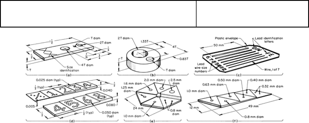
Fig. 54 Designs of several widely used penetrameters (image-quality indicators). (a) Rectangular plaque-
type
penetrameter (ASTM-
ASME standard) for plaque thicknesses of 0.13 to 1.3 mm (0.005 to 0.050 in.). (b)
Circular plaque-type penetrameter (ASTM-
ASME standard) for plaque thicknesses of 4.6 mm (0.180 in.) or
more. (c) Typical wire-type penetrameter (Deutsche Industrie Norm standard DIN 54109). (d) Square-
step step
wedge penetrameter used by British Welding Research Association (BWRA
standard). (e) Hexagonal and (f)
linear triangular-step step wedge penetrameters used by the French Navy (AFNOR standard).
Dimensions given
in inches, except where otherwise indicated
Applicable codes, specifications, or purchase agreements usually determine the type of penetrameter to be used. Even
when the specification does not require the use of a penetrameter, it is advisable to use a penetrameter to ensure that
appropriate image quality has been achieved. Some of the standard penetrameters, including those illustrated in Fig. 54,
are described below.
Plaque-type penetrameters consist of strips of materials of uniform thickness with holes drilled through them.
There are two general types of plaque penetrameters specified by ASTM and the American Society of Mechanical
Engineers (ASME): rectangular plaque penetrameters (Fig. 54a) and circular plaque penetrameters (Fig. 54b).
The rectangular plaque design shown in Fig. 54(a) is specified by ASTM and ASME for plaque thicknesses of 0.13 to 1.3
mm (0.005 to 0.050 in.). The holes in rectangular plaque penetrameters are T, 2T, and 4T in diameter, where T is the
thickness of the plaque. A notch system (Fig. 55) is also used to identify the ASTM grade of the penetrameter. For
example, the penetrameter shown in Fig. 54(a) would be a grade 1 penetrameter for testpiece materials in group 1 of
Table 8.
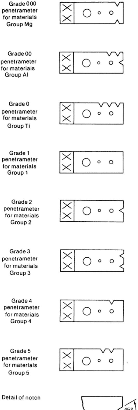

Fig. 55 Identification system of ASTM penetrameter material composition grades
The circular plaque design is larger than the rectangular plaque design and is specified for plaque thicknesses of 1.5 to 4
mm (0.060 to 0.160 in.). Figure 54(b) shows the circular design specified by ASTM and ASME for plaque-type
penetrameters with thicknesses of 4.6 mm (0.180 in.) or more.
Various degrees of image quality can be measured by using plaque-type penetrameters of different thicknesses.
Sensitivity is usually expressed in terms of penetrameter thickness (as a percentage of testpiece), and resolution is
determined by the smallest hole size visible in the radiograph. For example, an image-quality level of 2-2T indicates that
the thickness of the penetrameter equals 2% of section thickness and the 2T hole is visible. If image quality of 1-1T were
required, a radiograph would be acceptable if the outline of a 1% penetrameter were distinguishable. Alternatively, image
quality can be expressed as a percentage only. In the ASTM or ASME systems, the equivalent sensitivity in percent is
based on visibility of the 2T hole. Table 9 lists equivalent sensitivities for various standard image-quality levels.
Table 9 Equivalent sensitivities of various standard ASTM or ASME sensitivity levels
Equivalent sensitivity is a percentage equivalent for penetrameter thickness in which 2T is the smallest distinguishable hole size.
For
example, 1-1T is equivalent to 0.7-2T.
Image-quality
level
Penetrameter
thickness, %
of testpiece
thickness
Smallest
visible
hole size
Equivalent
sensitivity,
%
1-1T 1 1T
0.7
1-2T 1 2T
1.0
2-1T 2 1T
1.4
2-2T 2 2T
2.0
2-4T 2 4T
2.8
4-2T 4 2T 4.0
Wire-type penetrameters are widely used in Europe, and a standard design is used in the United Kingdom,
Germany, the Netherlands, and Scandinavia and by the International Organization for Standardization (ISO) and the
International Institute of Welding (IIW). In the United States, the penetrameter design specified in ASTM E 747 is widely
used. The ISO design of wire-type penetrameters has a group (typically seven) of straight 30 mm (1.2 in.) wires made of
the same material as the testpiece. The diameters of the seven wires are sized in a geometric progression from a range of
21 wire sizes with a numbered geometric progression of diameters ranging from wire number 1 (0.032 mm, or 0.00126
in., in diameter) to wire number 21 (3.200 mm, or 0.126 in., in diameter). This ISO standard is similar to the standard of
Deutsche Industrie Norm (DIN 54109), which consists of sixteen wire sizes of three metals--steel, aluminum, and copper.
However, the wire numbers in the DIN standard are the reverse of the ISO standard; in the DIN standard, wire diameters
decrease in geometric progression from wire number 1 (which has a 3.20 mm, or 0.126 in., diameter) to wire number 16
(which has a 0.10 mm, or 0.004 in., diameter).
The wire sizes on a wire penetrameter consist of different groupings. In the DIN system, for example, a wire penetrameter
may have one of three groupings of seven wire sizes:

• One group contains wire numbers 1 through
7, which correspond to wire diameters of 3.20 through 0.80
mm (0.126 through 0.031 in.)
• The second group (Fig. 54c) c
ontains wire numbers 6 through 12, which correspond to wire diameters
of 1.00 through 0.25 mm (0.039 through 0.010 in.)
•
The third group contains wire numbers 10 through 16, which correspond to wire diameters of 0.40
through 0.10 mm (0.016 through 0.004 in.)
Regardless of whether the wire type is designed to ISO, DIN, or ASTM specifications, image quality is denoted by the
wire number of the thinnest wire distinguishable on the radiograph. In contrast to the plaque system, however, the wire
system does not provide constant sensitivity, because the sensitivity varies with testpiece thickness. Therefore, the
equivalent sensitivities of wire penetrameter indications are defined for a range of testpiece thickness (as indicated in
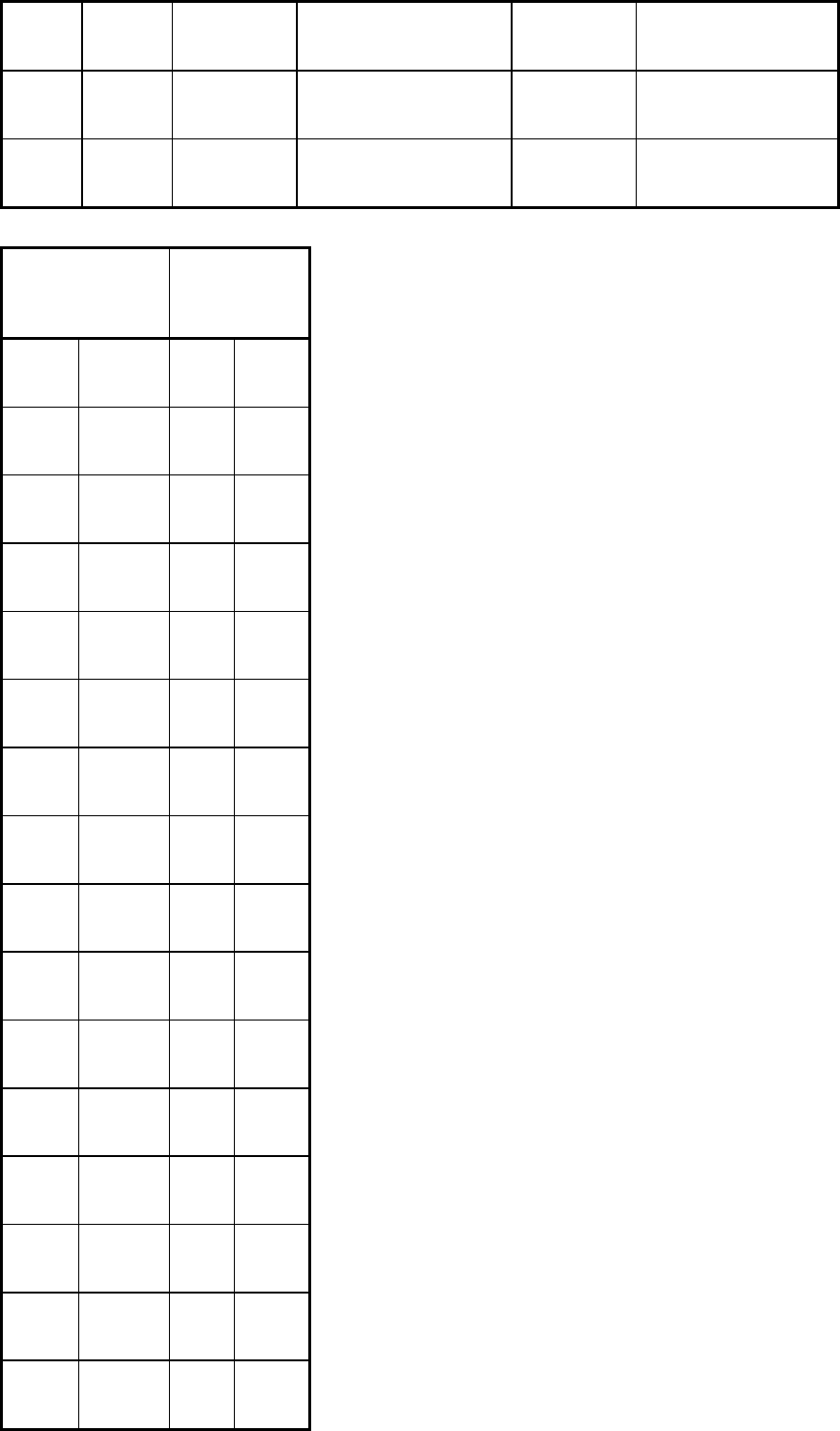
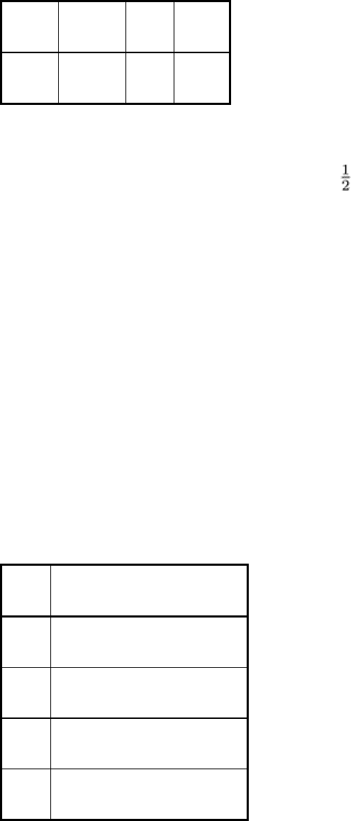
Table 10 for the DIN system). Table 11 lists the wire sizes equivalent to a 2-2T sensitivity for a variety of testpiece
thicknesses.
Table 10 DIN specification for minimum image quality and equivalent-sensitivity range for each range of
testpiece thickness
Minimum image quality is expressed as wire number (BZ) of thinnest wire distinguishable in radiograph.
Testpiece thickness
High-sensitivity level (category 1)
Normal-sensitivity level (category 2)
mm in. Wire No., BZ
Equivalent sensitivity, %
Wire No., BZ
Equivalent sensitivity, %
0-6 >0-0.25 16 1.7 min 14
2.7 min
6-8 0.25-0.30
15 2.0-1.6 13
3.3-2.5
8-10 0.30-0.40
14 2.0-1.6 12
3.1-2.5
10-16 0.40-0.60
13 2.0-1.3 11
3.2-2.0
16-25 0.60-1.00
12 1.6-1.0 10
2.5-1.6
25-32 1.00-1.25
11 1.3-1.0 9
2.0-1.6
32-40 1.25-1.60
10 1.3-1.0 8
2.0-1.6
40-50 1.60-2.00
9 1.3-1.0 7
2.0-1.6
50-80 2.00-3.15
8 1.3-0.8 6
2.0-1.3
80-200 3.15-8.00
7 1.0-0.4 . . .
. . .
80-150 3.15-6.00
. . . . . . 5
1.6-0.8
150-170
6.00-6.70
. . . . . . 4
1.1-0.9
170-180
6.70-7.00
. . . . . . 3
1.2-1.1
180-190
7.00-7.50
. . . . . . 2
1.4-1.3
190-200
7.50-8.00
. . . . . . 1 1.7-1.6
Table 11 Wire sizes equivalent to 2-2T hole-type levels
Minimum
specimen thickness
Wire diameter
mm in. mm
in.
6.35 0.25 0.1
(a)
0.004
(a)
9.5 0.375 0.13
(a)
0.005
(a)
13 0.500 0.16
0.0063
16 0.625 0.2
0.008
19 0.750 0.25
0.010
22 0.875 0.33
0.013
25 1.00 0.4
0.016
32 1.25 0.5
0.020
38 1.5 0.64
0.025
44 1.75 0.81
0.032
50 2 1.0
0.040
65 2.5 1.3
0.050
75 3 1.6
0.063
90 3.5 2.0
0.080
100 4 2.5
0.100
125 5 3.2
0.126
150 6 4.0 0.160
Source: ASTM E 747
(a)
Wire diameters for use with specimens less than 13 mm ( in.) in thickness do not represent the true 2-2T level. They follow the sam
e
relationship as the hole type.
Step wedge penetrameters usually have either an arithmetic or a geometric progression of step thicknesses. A plain
step wedge penetrameter is useful only for determining the ability of a radiograph to resolve variations in testpiece
thickness; it cannot be used to evaluate the effect of imaging unsharpness, which is often the chief factor that determines
image quality. However, if a plain step wedge is modified by drilling holes in each step, it becomes sensitive to imaging
unsharpness. This type of design is used by the British Welding Research Association (BWRA) and the French Navy
(AFNOR). In the BWRA design (Fig. 54d), the holes in a given step wedge are all of the same size--0.635 mm (0.025 in.)
diameter for the step wedge ranging from 0.13 to 1.0 mm (0.005 to 0.040 in.) in step thickness and 1.3 mm (0.050 in.)
diameter for the step wedge ranging from 1.0 to 2.0 mm (0.040 to 0.080 in.) in step thickness. AFNOR step wedges (Fig.
54e and f) have holes that are the same in diameter as the step thickness. The BWRA standard specifies a uniform
increment between step thicknesses; the AFNOR standard specifies a constant ratio between successive thicknesses
(similar to that of successive wire diameters in the DIN standard). The BWRA standard incorporates only two
penetrameters, both of which are shown in Fig. 54(d). The AFNOR standard specifies penetrameters having four different
series of step thicknesses, as follows:
Series
Step thicknesses, mm
1
0.125, 0.16, 0.20, 0.25, 0.32, 0.40
2
0.32, 0.40, 0.50, 0.63, 0.80, 1.00
3
0.80, 1.00, 1.25, 1.60, 2.00, 2.50
4 2.00, 2.50, 3.20, 4.00, 5.00, 6.30
The four series cover the entire range of testpiece thicknesses from about 4 to 300 mm (1.6 to 12 in.). Series 3 is
illustrated as a hexagonal penetrameter in Fig. 54(e), and series 2 is illustrated as a linear penetrameter in Fig. 54(f).
Both the BWRA and AFNOR penetrameters are sensitive to image definition and to contrast. Definition is judged on the
visibility of holes in the specified step. Sometimes, the image quality defined by a step wedge penetrameter is somewhat
ambiguous because the image can be evaluated both on the visibility of steps and on the visibility of holes. When contrast
is good and definition is poor, more steps than holes can be seen on the radiograph. However, when the image quality is
judged as intended--that is, on the visibility of individual holes for AFNOR penetrameters and on the visibility of the
symbol (not necessarily the visibility of individual holes) for BWRA penetrameters--the step wedge penetrameters are
quite sensitive to variations in radiographic technique. One minor limitation of AFNOR penetrameters is that the hole size
in the thinnest steps are comparable to the size of graininess visible in the radiograph. Sometimes it is not easy to be
certain that a hole is visible, but the use of two holes in the thinnest steps partly overcomes this limitation.
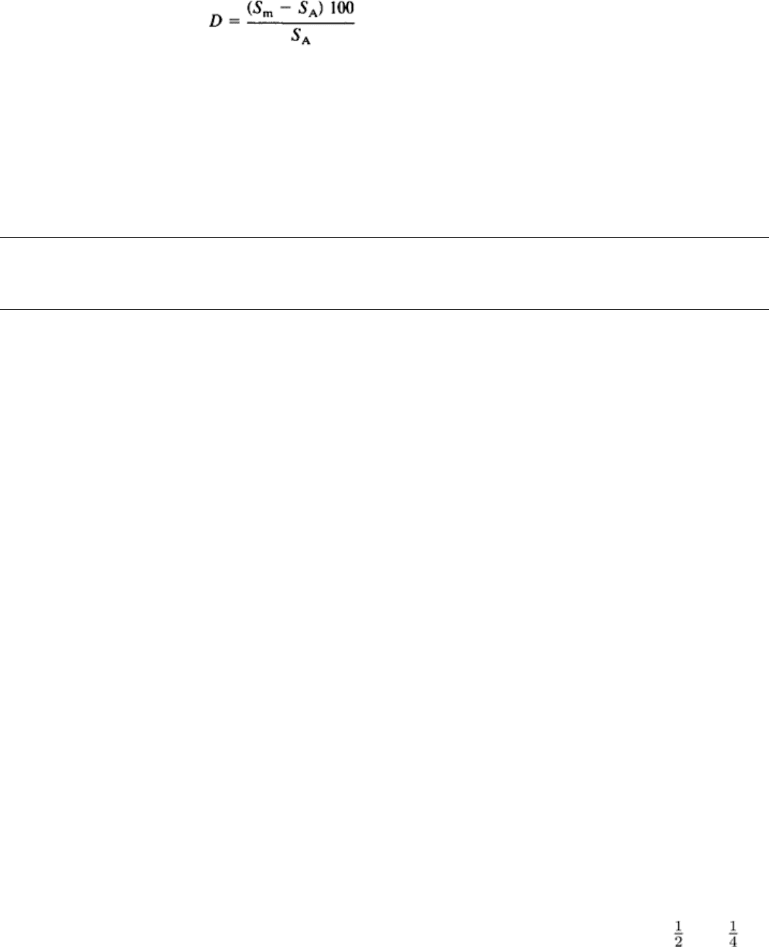
Penetrameters for electronic components use spherical particles and wire sizes, typical of the wire used in such
devices, for determinations of resolution or sensitivity. The wires are arranged in a three-dimensional grid with close-
toleranced spacing for the purpose of providing a measure of distortion. The image of the grid is measured on the
radiograph, and the distortion is calculated by:
(Eq 21)
where D is the percent distortion, S
m
is the wire spacing as measured on the radiograph, and S
A
is the actual wire spacing.
The ASTM standard E 801 describes a set of eight penetrameters having different cover thicknesses and wire sizes. The
cover densities and wire sizes are typical of the case materials and internal connecting wires of electronic components.
Two of these penetrameters are typically used for each exposure--usually the number having the density closest to that of
the component being radiographed and the next-higher-number penetrameter. Because electronic components are
typically exposed in groups, the penetrameters are placed at opposing corners of the group edges. This ensures that the
worst-case parameter values will be indicated.
Radiographic Inspection
Revised by the ASM Committee on Radiographic Inspection
*
Placement of Identification Markers and Penetrameters
The location of identification markers with respect to the testpiece is important only to the extent that shadows cast by the
identification markers should not obscure shadows cast by the testpiece itself. This is accomplished most easily by
attaching the lead letters or numbers to the film holder in a region outside the area being inspected, usually along the
edges of the holder. When it is important to ensure that identification markers do not obscure the image of some well-
defined region of the testpiece, such as a weld, it may be desirable to attach the identification markers to the testpiece
adjacent to that region.
When several views of the same testpiece are to be shot, it is good practice to attach an identification (view) marker to the
testpiece at each end of the area to be inspected in each view. These markers should be left in place until after the adjacent
exposures have been shot. Each view marker should be visible in two adjacent radiographs; if it is not, incomplete
coverage has been obtained. In some codes and specifications, this practice (known as sequence numbering) is required.
It is desirable to mark the testpiece with chalk, crayon, or a metal stamp to indicate the exact location of identification
markers. This can avoid possible difficulties either in identifying defective testpieces or in correlating radiographs with
testpieces.
The placement of penetrameters is important because incorrect placement with respect to the testpiece can result in an
incorrect assessment of image quality. On simple shapes, especially flat plates and similar shapes of uniform thickness, it
is seldom necessary to be concerned about factors other than placing the penetrameter where it will properly represent
maximum unsharpness, will not obscure any region being inspected, and will be located in the outer cone of the radiation
beam.
When the shape of a testpiece is complex or when there is a large variation in the thickness of the testpiece, placement of
penetrameters can be critical. Several suggested means of achieving proper placement of penetrameters are shown in Fig.
56 for welds between plates of different thickness and for circumferential welds in pipe. When no level testpiece surface
is available for placement of the penetrameter, penetrameter blocks placed beside the testpiece are the only reasonable
alternative. It is sometimes advantageous to use a stepped wedge as a penetrameter block, with the penetrameter on each
step. For example, in the technique used for three-view inspection of the large cast stainless steel impeller discussed in
Example 2 in this article, four penetrameters ranging in thickness from 0.25 to 1.15 mm (0.010 to 0.045 in.) were used for
six of the exposures. The four penetrameters, each placed on a different block between 13 and 57 mm ( and 2 in.)
thick, were needed for assurance that the specified level of image quality was achieved over the entire range of impeller
thicknesses.
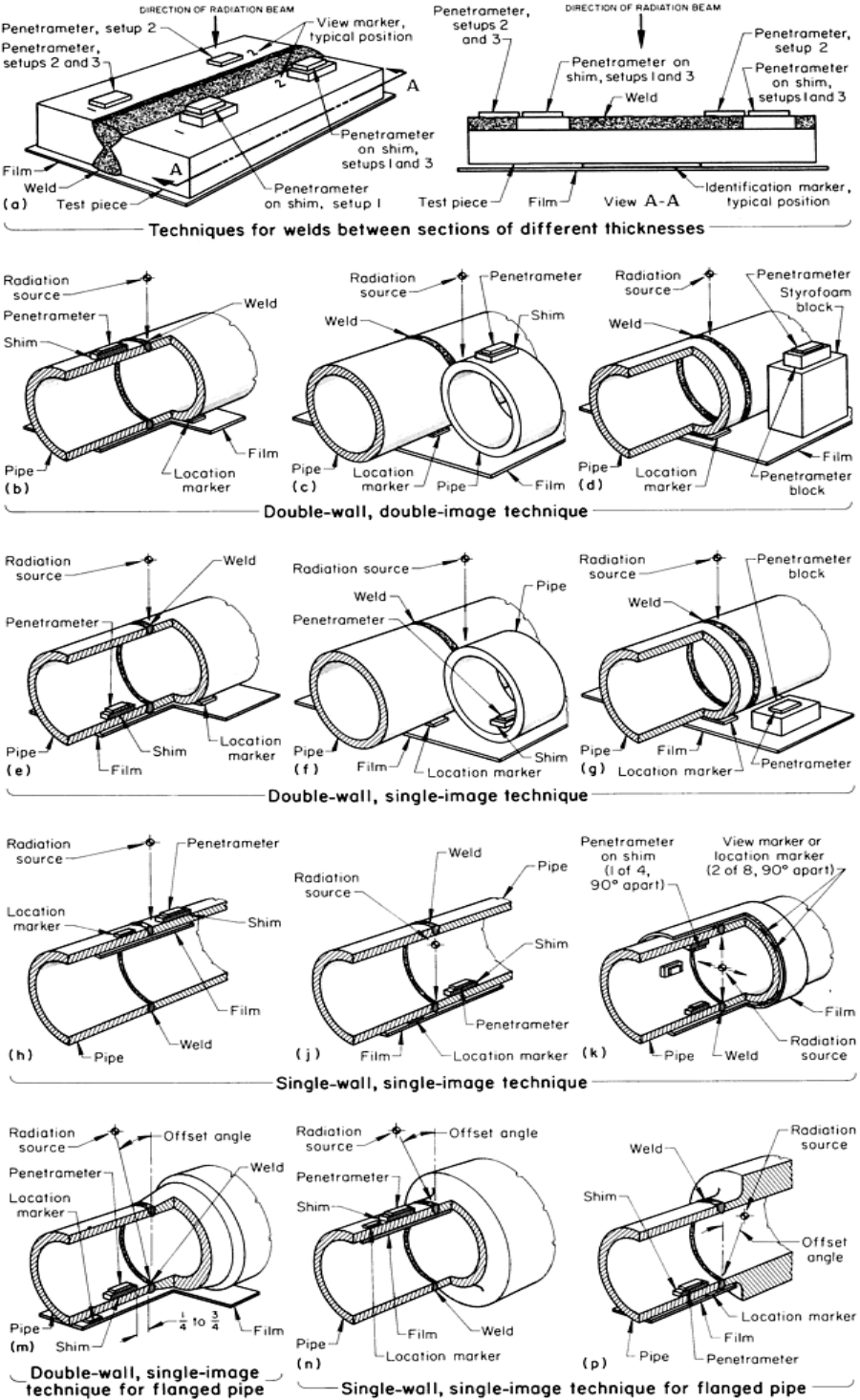

Fig. 56
Correct placement of view markers, location markers, and penetrameters for radiographic inspection.
Dimensions given in inches
Even though the following discussion and Fig. 56 illustrate the placement of markers and penetrameters on weldments,
similar locations for markers and penetrameters can be used on testpieces that do not contain welds. In all arrangements,
penetrameters should be placed in the outer cone of the radiation beam.
Radiography of Plates. Figure 56(a) illustrates three alternative arrangements of penetrameters and identification
markers for the radiography of a weld joining one plate to another plate of different thickness. In all three arrangements,
the identification markers and penetrameters are placed parallel to the weld. View markers and penetrameters are usually
placed 3 to 20 mm ( to in.) from the edge of the weld zone, but no more than 40 mm (1 in.). Testpiece
identification markers, however, can be placed farther away if necessary to ensure that their image is outside the image of
the weld zone in the processed radiograph. Identification markers are usually placed on the film but view markers should
be placed on the surface of the testpiece closest to the radiation source so that correct overlap between adjacent exposures
can be verified. (If the view markers were located on the film side, a portion of the testpiece directly above the view
markers could be missed even though the images of the markers appeared in adjacent radiographs.)
In Fig. 56(a), the preferred setup (setup 1) has two penetrameters located on the thinner plate. In the alternative setups
(setups 2 and 3), two penetrameters are located on the thicker plate (setup 2) or one penetrameter on each plate (setup 3).
Shims made of an alloy that has the same absorption characteristics as the weld metal are used under the penetrameters in
each instance to compensate for any difference between the thickness of the weld zone, including reinforcement, and the
thickness of the plate on which the penetrameter is located. Any shim used should be larger than the penetrameter placed
on it, so that the image of the penetrameter can be clearly seen within the umbral image of the shim. Also, the direction of
radiation with respect to shim and penetrameter location should be considered, especially with thick shims or
penetrameter blocks, to ensure that the shim properly represents the effective penetrated thickness of the testpiece.
Some codes and specifications require that the image of a penetrameter be used to evaluate the quality of only that portion
of the radiographic image of the testpiece that has similar photographic density. Strict limits can be placed on the
allowable density difference between penetrameter image and testpiece image. For this reason, it may be necessary to use
two or more penetrameters to evaluate image quality in different regions on the radiograph. When plaque-type
penetrameters are used, plaques of different thickness are used for different regions, depending on testpiece thickness in
each region.
Radiography of Cylinders. Figures 56(b), 56(c), and 56(d) illustrate alternative locations for markers and
penetrameters for the double-wall, double-image radiography of hollow cylinders or welded pipe. These alternatives can
be used for either normal or offset (corona) views. When the penetrameter is placed on the cylinder itself, as shown in
Fig. 56(b), or on a short section of pipe having the same diameter and wall thickness as the pipe being inspected, as
shown in Fig. 56(c), any shim that is used under the penetrameter should be only thick enough to compensate for weld
reinforcement; that is, twice the nominal reinforcement for a normal view, but equal to the nominal reinforcement for an
offset (corona) view. If the testpiece is a plain cylinder or if a circumferential butt weld is flush with the surface, no shim
is needed. When a penetrameter block is used to provide equivalent penetrated thickness under the penetrameter, the
block thickness should equal twice the nominal wall thickness of the cylinder plus twice the nominal weld reinforcement.
Also, the penetrameter block should be set on a block of Styrofoam or similar nonabsorbing material so that the upper
surface of the penetrameter block is aligned with the upper surface of the pipe, as shown in Fig. 56(d). When a short
section of pipe is used under the penetrameter (Fig. 56c), the radiation source should be centered between the pipe being
inspected and the short pipe section; otherwise, the radiation source should be centered above the pipe being inspected.
To ensure that the penetrameter image is within the umbral region of the image of a shim or penetrameter block, the
penetrameter should be aligned with the edge of the shim or block closest to the central beam of radiation.
Figures 56(e), 56(f), and 56(g) illustrate alternative setups for the double-wall, single-image radiography of hollow
cylinders or welded pipe. These alternatives are suitable for both normal and offset (corona) views. As for a double-wall,
double-image technique, the penetrameter can be placed on the pipe itself--on a short section of pipe being inspected or
on a penetrameter block. The setup illustrated in Fig. 56(e) can be used when there is access to the inside of the pipe for
placement of the penetrameter. When a shim is used under the penetrameter (Fig. 56e and f), it should be equal to the
height of nominal weld reinforcement, regardless of the view that is used. When there is no reinforcement, no shim is
needed. If the penetrameter is placed on a penetrameter block, as in Fig. 56(g), the block should be equal to twice the
