ASM Metals HandBook Vol. 17 - Nondestructive Evaluation and Quality Control
Подождите немного. Документ загружается.


theoretical evaluation. Compton scattering varies directly with the atomic number of the scattering element and varies
approximately inversely with the photon energy in the energy range of major interest.
Pair production is an absorption process that creates two 0.5-MeV photons of scattered radiation for each photon of
high-energy incident radiation consumed; a small amount of scattered radiation of lower energy also accompanies pair
production. Pair production is more important for heavier elements; the effect varies with atomic number, Z,
approximately as Z(Z + 1). The effect also varies approximately logarithmically with photon energy.
In pair production, a photon of incident electromagnetic radiation is consumed in creating an electron-positron pair that is
then ejected from an atom. This effect is possible only at photon energies exceeding 1.02 MeV because, according to the
theory of relativity, 0.51 MeV is consumed in the creation of the mass of each particle, electron, or positron. Any energy
of the incident photon exceeding 1.02 MeV imparts kinetic energy to the pair of particles.
The positron created by pair production is destroyed by interaction with another electron after a very short life. This
destruction produces electromagnetic radiation, mainly in the form of two photons that travel in opposite directions, each
photon having an energy of about 0.5 MeV. Most of the electrons created by pair production are absorbed by the material,
producing bremsstrahlung of energy below 0.5 MeV.
Total absorption is the sum of the absorption or scattering effects of the four processes. The atomic absorption
coefficient can be expressed as:
a
=
pe
+
R
+
C
+
pr
(Eq 7)
where
pe
is the attenuation due to the photoelectric effect,
R
is that due to Rayleigh scattering,
C
is that due to
Compton scattering, and
pr
is that due to pair production.
From calculated atomic absorption coefficients, the mass absorption coefficient can be determined by multiplying
a
by
Avogadro's number, N, and dividing by the atomic weight of the element, A:
(Eq 8)
Figure 21 shows the variation of the mass absorption coefficient for uranium as a function of photon energy and indicates
the amount of total absorption that is attributable to the various atomic processes over the entire range of 10 keV to 100
MeV. Tables of cross sections and absorption coefficients for 40 of the more usually encountered elements at various
photon energies from 0.01 to 30 MeV are presented in Ref 1. Absorption coefficients can be evaluated for alloys,
compounds, and mixtures by calculating a weighted-average mass absorption coefficient in proportion to the relative
abundance of the constituent elements by weight.
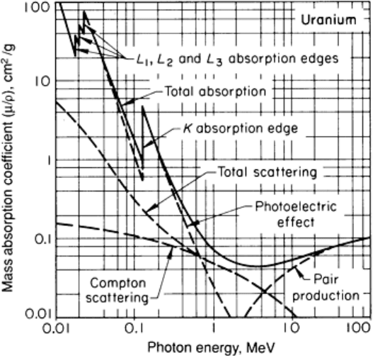
Fig. 21
Calculated mass absorption coefficient for uranium as a function of photon energy (solid line) and
contributions of various atomic processes (dashed lines). Rayleigh scattering is the difference between total
scattering and Compton scattering.
Effective Absorption of X-Rays
The preceding discussion of mass absorption and atomic absorption characteristics is based on the assumption of so-
called narrow-beam geometry, in which any photon that is scattered, no matter how small the angle, is considered
absorbed. Experimentally, narrow-beam geometry is approximated by interposing a strong absorber such as lead between
the material being evaluated and the radiation detector, then allowing the beam of attenuated radiation to pass through a
small hole in the absorber to impinge on the detector. Only total absorption can be determined experimentally; however, it
has been shown that the sum of calculated absorption coefficients for the various atomic processes correlates closely with
experimentally determined narrow-beam absorption coefficients for a wide variety of materials and photon energies.
Broad-Beam Absorption. The evaluation of absorption coefficients under narrow-beam geometry is mainly a
convenience that simplifies theoretical calculations. Whenever there is a measurable width to the radiation beam, narrow-
beam conditions no longer exist, and absorption must be evaluated under so-called broad-beam geometry. Under broad-
beam geometry, photons that are scattered forward at small angles are not lost, but increase the measured intensity of the
attenuated beam. Therefore, the broad-beam absorption coefficient of any material is less than the narrow-beam
absorption coefficient.
There are many degrees of broad-beam geometry, depending on the portion of the attenuated-beam intensity that is
comprised of scattered radiation. However, broad-beam absorption characteristics are usually determined in such a
manner that variations in the areas of either the radiation beam or the testpiece have no effect on the intensity of the
transmitted radiation. Therefore, broad-beam absorption coefficients are useful because the ordinary radiographic
arrangement (in which the film or screen is placed in close proximity to the testpiece) effectively duplicates this
condition.
Effect of Radiation Spectrum. The theoretical assessment of absorption characteristics is based on an assumption of
monoenergetic radiation (radiation having a single wavelength). As Fig. 11 shows, the actual output of an x-ray tube is
not monoenergetic; for example, 200-kV x-rays have an upper limit of 200 keV of photon energy and are comprised of a
broad spectrum of x-rays having lower photon energies. Even if an incident beam were monoenergetic, it would soon
contain x-rays of lower photon energies because of Compton scattering. Therefore, in addition to the effect of broad-beam
geometry, the effective absorption coefficients of materials are further modified by the multienergetic character of
impinging radiation. The correction of calculated absorption coefficients for the known wavelength distribution of a beam
of x-rays is time consuming but not impossible.
Empirical values of absorption coefficients based on broad-beam experiments are the values that are most useful in
exposure calculations, because these values are corrected for both broad-beam geometry and the variation of intensity
with photon energy in the incident radiation. Published values of calculated absorption coefficient are based on narrow-
beam geometry. If these values are used to estimate radiographic exposures, the estimates may be inaccurate, especially
for low-to-medium energy radiation from an x-ray tube and for relatively thick testpieces.
Scattering Factor. The ratio of the intensity of scattered radiation, I
S
, to the intensity of direct radiation, I
D
, impinging
on the detector is known as the scattering factor and is important in determining image quality. Scattered radiation does
not reveal characteristics of the testpiece; it only reduces radiographic contrast, obscuring detail and reducing
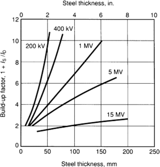
radiographic sensitivity. The scattering factor is a function of photon energy and the thickness, density, and material type
(μ/ρ) of the testpiece. Figure 22 illustrates an example of experimental values for the build-up factor (1 + I
S
/I
D
) with steel.
Fig. 22 Experimental values of build-up factor for different thicknesses of steel and different x-
ray energies.
Source: Ref 2
Because radiation of low photon energy is scattered more than radiation of high photon energy, it is desirable to use
relatively high-energy radiation for optimum radiographic subject contrast. This can be accomplished by either raising the
voltage of the x-ray tube, which moves the entire bremsstrahlung spectrum to higher photon energies, or by interposing a
filter between the source and the testpiece, which effectively raises photon energy by selectively absorbing or scattering
the long wavelength portion of the spectrum. The optimum choice of filter material and thickness varies with different
combinations of testpiece material and thickness, film or detector type, and bremsstrahlung spectrum as determined by the
type of x-ray tube and tube voltage used. Also, the optimum combinations of filter material and thickness, and tube
current and exposure time, must be evaluated on the basis of a compromise between image quality and costs. Generally,
filters made of metals having high atomic numbers (lead, for example) produce a cleaner image because of a reduction in
the amount of scattered radiation. However, such filters also cause a large reduction in the intensity of the radiation beam,
which leads to greater expense because of the need for longer exposure times with films or more sensitive detector
systems in real-time radiography. Also, because long wavelength radiation is absorbed preferentially, there is a reduction
in the ability to image very small flaws.
Raising the voltage of the x-ray tube, which is sometimes restricted by equipment limitations, does not necessarily
involve a compromise between image quality and costs. In fact, high-voltage x-ray equipment is frequently capable of
producing higher-quality radiographs at reduced cost. Image quality is improved primarily by reducing the proportion of
the image background that is directly attributable to scattered radiation. For example, 80% or more of the photographic
density of a given film may be attributed to non-image-forming scattered radiation when low-voltage (soft) x-rays are

employed. On the other hand, for a 100 mm (4 in.) thick steel testpiece, only about 40% of the photographic density is
caused by scattered radiation when the incident beam is 1.3-MeV radiation and only about 15% with 20-MeV x-rays.
Radiographic Equivalence. The absorption of x-rays and -rays by various materials becomes less dependent on
composition as radiation energy increases. For example, at 150 keV, 25 mm (1 in.) of lead is equivalent to 350 mm (14
in.) of steel, but at 1000 keV, 25 mm (1 in.) of lead is equivalent to only 125 mm (5 in.) of steel. Approximate
radiographic absorption equivalence factors for several metals are given in Table 5. When film exposure charts are
available only for certain common materials (such as steel or aluminum), exposure times for other materials can be
estimated by determining the film exposure time for equal thickness of a common material from the chart, then
multiplying by the radiographic equivalence factor for the actual testpiece material (see the section "Exposure Factors" in
this article for detailed information on radiographic exposure).
Table 5 Approximate radiographic absorption equivalence for various metals
X-rays, keV X-rays, MeV
γ-rays
Materials
50 100 150 220 450
1 2 4 to 25
Ir-192
Cs-137
Co-60
Ra
Magnesium 0.6
0.6 0.05
0.08
. . . . . .
. . .
. . . . . . . . . . . .
. . .
Aluminum 1.0
1.0 0.12
0.18
. . . . . .
. . .
. . . 0.35 0.35 0.35
0.40
Aluminum alloy 2024
2.2
1.6 0.16
0.22
. . . . . .
. . .
. . . 0.35 0.35 0.35
. . .
Titanium . . .
. . . 0.45
0.35
. . . . . .
. . .
. . . . . . . . . . . .
. . .
Steel . . .
12.0
1.0 1.0 1.0 1.0
1.0
1.0 1.0 1.0 1.0
1.0
18-8 stainless steel . . .
12.0
1.0 1.0 1.0 1.0
1.0
1.0 1.0 1.0 1.0
1.0
Copper . . .
18.0
1.6 1.4 1.4 . . .
. . .
1.3 1.1 1.1 1.1
1.1
Zinc . . .
. . . 1.4 1.3 1.3 . . .
. . .
1.2 1.1 1.0 1.0
1.0
Brass
(a)
. . .
. . . 1.4 1.3 1.3 1.2
1.2
1.2 1.1 1.1 1.1
1.1
Inconel alloys . . .
16.0
1.4 1.3 1.3 1.3
1.3
1.3 1.3 1.3 1.3
1.3
Zirconium . . .
. . . 2.3 2.0 . . . 1.0
. . .
. . . . . . . . . . . .
. . .
Lead . . .
. . . 14.0
12.0
. . . 5.0
2.5
3.0 4.0 3.2 2.3
2.0
Uranium . . .
. . . . . . 25.0
. . . . . .
. . .
3.9 12.6 5.6 3.4 . . .
(a)
Containing no tin or lead; absorption equivalence is greater than these values when either
element is present.
References cited in this section
1.
Radiography & Radiation Testing, Vol 3, 2nd ed., Nondestructive Testing Handbook, Ame
rican Society for
Nondestructive Testing, 1985
2.
R. Halmshaw, Nondestructive Testing, Edward Arnold Publishers, 1987
Radiographic Inspection
Revised by the ASM Committee on Radiographic Inspection
*
Principles of Shadow Formation
The image formed on a radiograph is similar to the shadow cast on a screen by an opaque object placed in a beam of light.
Although the radiation used in radiography penetrates an opaque object whereas light does not, the geometric laws of
shadow formation are basically the same. X-rays, -rays, and light all travel in straight lines. Straight-line propagation is
the chief characteristic of radiation that enables the formation of a sharply discernible shadow. The geometric
relationships among source, object, and screen determine the three main characteristics of the shadow--the degrees of
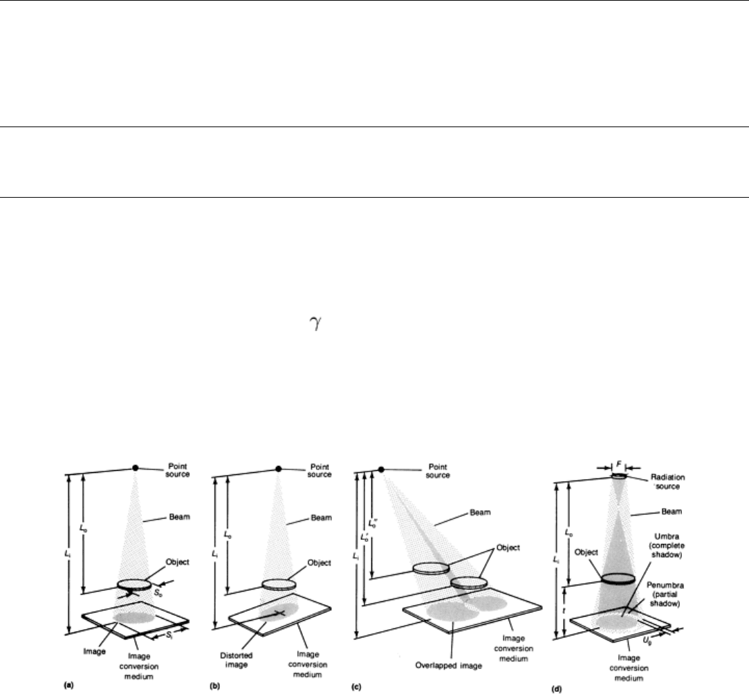
enlargement, distortion, and unsharpness (Fig. 23). This theoretical unsharpness is added to the scattering from the atomic
attenuation processes (photoelectric effect, Rayleigh and Compton scattering, and pair production, as mentioned in the
previous section) to obtain the total unsharpness and blurring of the image.
Fig. 23
Schematic of the effect of geometric relationships on image formation with point sources and a
radiation s
ource of finite size. (a) Image enlargement, (b) image distortion, and (c) image overlap for point
sources of radiation. (d) Degree of image unsharpness from a radiation source of finite size. L
o
, source-to-
object distance; L
i
, source-to-image distance; S
o
, size of object; S
i
, size of image; U
g
, geometric unsharpness;
F, size of focal spot; t, object-to-image distance
Enlargement. The shadow of the object (testpiece) is always farther from the source than the object itself. Therefore, as
illustrated for a point source in Fig. 23(a), the dimensions of the shadow are always greater than the corresponding
dimensions of the object. Mathematically, the size of the image or degree of enlargement can be calculated from the
relationship:
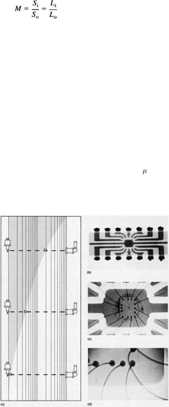
(Eq 9)
where M is the degree of enlargement (magnification), S
i
is the size of the image, S
o
is the size of the object, L
i
is the
source-to-film or source-to-detector distance, and L
o
is the source-to-object distance.
Variations in the position of a given object relative to the source and recording surface affect image size. For example,
when the source-to-image distance, L
i
, is decreased without changing the distance of the object from the image, the size of
the image, S
i
, is increased. Alternatively, when the source-to-object distance, L
o
, is increased without changing the
distance of the recording surface from the source (L
i
constant), the size of the image is decreased.
Film Radiography. The effect of enlargement is normally of little consequence in film and paper radiography, mainly
because the recording medium is placed close behind the testpiece to minimize geometric unsharpness. Even with this
arrangement, however, images of portions of the testpiece farthest from the recording plane will be larger than
corresponding portions of the testpiece itself. This effect is greatest for short source-to-image distances.
Microradiography and Real-Time Radiography. There are certain circumstances when enlargement is
advantageous. In real-time radiography, for example, the significance of screen unsharpness can be minimized by
positioning a testpiece closer to the source. Details that are otherwise invisible in a radiograph can also be enlarged
enough to become visible. This technique has been used for microradiography, in which considerable enlargement renders
minute details visible. Because of geometric unsharpness, however, only sources with extremely small focal spots can be
used to produce enlarged radiographs. For example, focal spots approximately 5 m (0.2 mil) in diameter are used for
microradiography (Fig. 24). One shortcoming of this technique may be a low level of radiation intensity, which could
limit applications to the inspection of low-density materials. Nevertheless, real-time microradiography has found
application in the inspection of high-quality castings and high-integrity weldments.
Fig. 24 Geometric magnification of radiographic images with a microfocus x-
ray tube. (a) Greater geometric
magnification and unsharpness occur when the testpiece is moved away from the detector and toward the
radiation source. With a microfocus x-ray tube, however, the amount of geometric unsharpness (Eq 11
) is
minimized, as shown by an integrated circuit magnified at 1.25× (b), 20× (c), and 40× (d).
Courtesy of
Rockwell International
Reduction of Scattering. Another advantage of placing the testpiece closer to the source is a reduction of secondary
(scattered) radiation. When the magnification factor, M, in Eq 9 is greater than 3, the build-up factor, 1 + I
S
/I
D
, approaches
1 (Ref 2).
Distortion. As long as the plane of a two-dimensional object and the plane of the imaging surface are parallel to each
other, the image will be undistorted regardless of the angle at which the beam of radiation impinges on the object. In
addition, the degree of enlargement at different points in a given image is constant because the ratio L
i
/L
o
is invariant.
However, as shown in Fig. 23(b), if the plane of the object and the plane of the recording surface are not parallel, the
image will be distorted because the degree of enlargement is different between rays passing through any two points on the
surface of the object. This is the main reason radiographic images almost always present a distorted picture of testpiece
features; the shape of most testpieces is such that one or more of its features is not parallel to the imaging surface. The
degree of distortion is directly related to the degree of nonparallelism; small amounts of nonparallelism produce small
degrees of distortion, and large amounts produce large degrees of distortion.
Although there is no distortion of images of features that are parallel to the imaging surface, spatial relationships among
testpiece features are distorted, with the amount of distortion being directly related to the cosine of the angle of the beam
to the imaging surface. For example, two circular features that are parallel to the imaging surface but at different object-
to-detector distances may produce two separate circular images, or one noncircular image because two images overlap, as
shown in Fig. 23(c), depending on the direction of the radiation beam. In most actual radiographs, regions where images
of different features overlap will appear as regions of greater or lesser contrast than adjacent regions where the images do
not overlap, depending on whether the features absorb less radiation or more radiation than portions of the testpiece
surrounding the features. For example, overlapping images of voids or cavities will appear darker on film or brighter on
fluorescent screens in regions of overlap because less radiation is absorbed along paths intersecting overlapping voids
than along paths that intersect only one void.
Geometric Unsharpness. In reality, any radiation source is too large to be approximated by a point. Conventional x-
ray tubes have focal spots between 2 by 2 mm (0.08 by 0.08 in.) and 5 by 5 mm (0.2 by 0.2 in.) in size, while microfocus
x-ray systems have focal-spot sizes as small as 5 m (0.2 mil). Even high-energy sources have focal spots of appreciable
size, although seldom exceeding 2 mm (0.08 in.) in diameter. Gamma-ray sources vary widely in size, depending on
source strength and specific activity, but are seldom less than about 2.5 mm (0.1 in.) in diameter.
Radiographic definition varies according to the geometric relationships among source size, source-to-object distance, and
object-to-image distance. When radiation from a source of any finite size produces a shadow, that portion of the image
that is in shadow for radiation emanating from all points on the surface of the source is a region of complete shadow
known as the umbra. Portions of the image that are in shadow for radiation emanating from any portion of the source, but
not in shadow for radiation from some portion, are regions of partial shadow known as the penumbra. The degree of
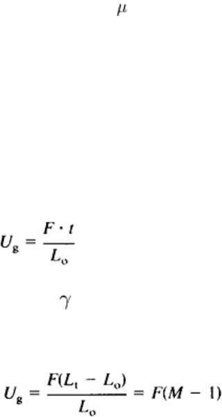
geometric unsharpness is equal to the width of the penumbra. Mathematically, the geometric unsharpness, U
g
, is
determined from the laws of similar triangles, as illustrated in Fig. 23(d), and can be expressed as:
(Eq 10)
where F is the size of the focal spot -ray source, t is the object-to-image distance, and L
o
is the source-to-object
distance. In most cases, t is considered to be the difference between the source-to-image distance, L
i
, and the source-to-
object distance, L
o
; therefore, Eq 10 can be alternatively expressed as:
(Eq 11)
The size of the penumbra, or the geometric unsharpness, can be reduced by lengthening the source-to-object distance, by
reducing the size of the focal spot, or by reducing the object-to-image distance. In practice, the source size is determined
by the characteristics of a given x-ray tube or by the physical dimensions of a radioactive pellet, and the object-to-image
distance is minimized by placing the surface of the imaging medium as close as possible to the testpiece. Therefore, the
only variable over which the radiographer has any appreciable amount of control is source-to-object distance. However,
as discussed in the following section in this article, this distance is a significant variable affecting the intensity of the
penetrating radiation. Consequently, the radiographer often must compromise between maximum definition (minimum
unsharpness) and the cost associated with the lower radiation intensity that occurs when the source-to-object distance is
increased. Higher costs in film radiography occur with a lower intensity of radiation because exposure time must be
increased. In real-time radiography, costs may be less of a factor, but increases in detector efficiency or image-processing
time might be required.
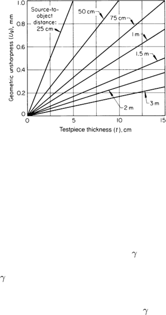
Geometric unsharpness is one of several unsharpness factors and is usually the largest contributor to unsharpness in film
radiography. When the distance between the actual surface of the imaging medium and the adjacent (facing) surface of
the testpiece is neglected (which is an appropriate assumption in film radiography because this distance is usually quite
small in relation to testpiece thickness), the geometric unsharpness can be calculated for any source size and can be
expressed as a series of straightline plots relating geometric unsharpness, U
g
, to testpiece thickness, t, for various values
of the source-to-object distance, L
o
. A typical series is shown in Fig. 25 for a 5 mm (0.2 in.) diam source. It is often
helpful to prepare graphs such as the one in Fig. 25 for each source size used.
Fig. 25 Relation of geometric unsharpness to testpiece thickness for various source-to-
object distances when
the source is 5 mm (0.2 in.) in diameter
In applications where the maximum unsharpness must be kept below a specific known value to resolve certain types and
sizes of flaws, the radiographer can determine the minimum source-to-object distance for a given part from Eq 10. At this
value of L
o
, the types and sizes of flaws to which the specified value of U
g
applies will be resolved if the flaws are in the
plane of the testpiece farthest from the imaging surface. Flaws in planes closer to the imaging surface will be even more
clearly resolved.
Shadow Intensity and the Inverse-Square Law. The intensity of radiation that penetrates a testpiece and
produces a satisfactory image is governed by the energy and spectral quality of the incident radiation, the strength of the
radiation, and the source-to-detector distance. In practice, the energy of the incident radiation, which depends mainly on
the tube voltage of an x-ray machine or on the radioactive isotope in a -ray source, is chosen to be sufficiently
penetrating for the type of material and thickness to be inspected. With this factor fixed, the remaining interrelated
factors--the source strength (determined by tube current in milliamperes for x-ray sources or by source activity in
becquerels, or curies, for -ray sources) and the source-to-detector distance--determine the intensity of radiation
impinging on the detector.
The intensity of the shadow image determines the amount of exposure time for a given (fast or slow) film or the detector
efficiency required in real-time radiography. Similar to visible light, x-rays or -rays diverge when emitted from the

radiation source and cover an increasingly larger area, with lessened intensity, as the distance from the source increases.
The intensity, or amount of radiation falling on a unit area per unit time, varies inversely with the square of the distance
from the source. This can be expressed mathematically as:
IL
2
= constant
(Eq 12)
where I is the intensity of radiation at a given distance, L, from a source of given strength. More often, the inverse-square
law is expressed as a ratio:
(Eq 13)
where the subscripts 1 and 2 refer to different points along a line radiating from the source. Because of this inherent
characteristic of radiation, if the radiation has a certain intensity at 1 m (3.3 ft) from the source, it will have four times that
intensity at 0.5 m (1.65 ft) but only one-fourth that intensity at 2 m (6.6 ft) and only one-ninth that intensity at 3 m (9.9
ft).
Scattered Radiation. When a beam of x-rays or -rays strikes a testpiece, secondary radiation is scattered in all
directions. This causes a haze over all or part of the image, thus reducing contrast and visibility of detail. Methods for
reducing scattered radiation are discussed in the section "Control of Scattered Radiation" in this article.
Internal scatter occurs within the testpiece being radiographed (Fig. 4a). Internal scatter is fairly uniform throughout a
testpiece of uniform thickness, but adversely affects definition by diffusing or obscuring the outline of the image.
Side scatter consists of secondary radiation generated by walls, internal holes in the testpiece (as shown in Fig. 4b), or
objects near the testpiece. This radiation may pass through the testpiece and may obscure the image of the testpiece.
Back scatter consists of rays that are generated from the floor or table (Fig. 4c) or from any other object that is located
on the opposite side of the imaging surface from the testpiece and source. Back scatter increases the background noise
and therefore reduces contrast and definition in the recorded image.
Reference cited in this section
2.
R. Halmshaw, Nondestructive Testing, Edward Arnold Publishers, 1987
Radiographic Inspection
Revised by the ASM Committee on Radiographic Inspection
*
Image Conversion Media
After penetrating the testpiece, the x-rays or γ-rays pass through a medium on the imaging surface. This medium may be a
recording medium (such as film) or a medium that responds to the intensity of the radiation (such as fluorescent screen or
a scintillation crystal in a discrete detector). These two types of media provide the images for subsequent observation.
Radiography can also utilize radiographic screens, which are pressed into intimate contact with the imaging medium.
Radiographic screens include:
• Metallic screens placed over film, paper, or the screens used in real-time systems
• Fluorescent screens placed over film or photographic paper
• Fluorometallic screens placed over film
These screens are used to improve radiographic contrast by intensifying the conversion of radiation and by filtering the
lower-energy radiation produced by scattering.
Recording Media
By definition, a radiographic recording medium provides a permanent visible image of the shadow produced by the
penetrating radiation. Permanent images are recorded on x-ray film, radiographic paper, or electrostatically sensitive
paper such as that used in the xeroradiographic process.
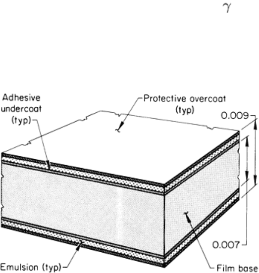
X-ray film is constructed of a thin, transparent plastic support called a film base, which is usually coated on both sides
(but occasionally on one side only) with an emulsion consisting mainly of grains of silver salts dispersed in gelatin (Fig.
26). These salts are very sensitive to electromagnetic radiation, especially x-rays, -rays, and visible light. The film base
is usually tinted blue and is about 0.18 mm (0.007 in.) thick. An adhesive undercoat fastens the emulsion to the film base.
A very thin but tough coating of gelatin called a protective overcoat covers the emulsion to protect it against minor
abrasion. The total thickness of the x-ray film is approximately 0.23 mm (0.009 in.), including film base, two emulsions,
two adhesive undercoats, and two protective overcoats.
Fig. 26 Schematic cross section of a typical x-ray film. Dimensions given in inches
The presence of emulsions on both sides of the base effectively increases the speed of the x-ray film because penetrating
radiation affects each emulsion almost equally. In addition, thin emulsions allow development, fixing, and washing of the
exposed film to be accomplished effectively and in a reasonably short time. Where two emulsions are used, two images
are produced--one in the front emulsion and one in the back emulsion. Viewing these images with the unaided eye causes
no problems, because the images are separated by only a few hundredths of a millimeter of film base. However, if
magnification is used, parallax can cause the two images to be seen slightly separated, which sometimes hampers
interpretation. When appropriate, x-ray film with only one emulsion (single-coated x-ray film) can be used to avoid
parallax.
When electromagnetic radiation and certain forms of particulate radiation (namely, electrons) react with the sensitive
emulsion of x-ray films, they produce a latent image in the emulsion, which cannot be detected visually or by ordinary
physical measurements. To produce a visible image, the exposed film must be chemically processed. When the film is
treated with a developer, selective chemical reaction converts the exposed silver halide grains in the latent image into
black metallic silver. The metallic silver remains suspended in the gelatin and is responsible for blackening or shades of
gray in the developed (visible) image. After development, the film is treated with a chemical called a fixer, which
converts unexposed silver halide grains into a water-soluble compound. The reaction products of development and fixing
