ASM Metals HandBook Vol. 17 - Nondestructive Evaluation and Quality Control
Подождите немного. Документ загружается.


Extra layers of film adhesive X X
Foreign objects X X X
X
Double drilled or irregular holes X X
Disbonds, low core X
Void or gap, chemical milled land X
Void or gap, doublers X
Missing fillets X
Void, closure-to-core X
High-density inclusions (chips, etc.) X X
X
Voids, foam joint X X
Disbond, shear ties X X
Lack of sealant at fasteners X
Thick foam adhesive X
Broken fasteners X X
Crushed core X
Wrinkled core X
Condensed core X
Distorted core X
Blown core X
Node bond separation X
Missing core (short core) X X
Cut core X X
Water in core X
Cracks X
Scratches X
Blisters X
Protrusions X
Indentations (dents/dings) X
Wrinkles X
Pits X
Source: Ref 1
Table 2 Frequency of rejectable flaws in adhesive-bonded assemblies
Defect Number of
defects
Percentage
of total
Metal-to-metal voids and disbonds 378
74
Skin-to-core voids and disbonds 19
3
Gap in core-to-closure bond 9
2
Lack of foaming adhesive or voids in foaming adhesive
22
4
Difference in core density 6
2
Lack of fillets 1
1
Crushed or missing core 32
6
Short core 40
8
Total 507 100
Interface defects are the result of errors made during the pretreatment cycle of the adherends prior to the actual bonding
process. In practice, pretreatment flaws are reduced by careful process control and by adherence to specification
requirements and inspection before proceeding with the bond cycle. Controls generally include the waterbreak test and
measurement of the anodic layer and primer thickness. Interface defects can be caused by improper or inadequate
degreasing, deoxidizing, anodizing, drying, damage to the anodizing layer, or excessive primer thickness.
Interface defects are generally not detectable by state-of-the-art NDT methods. Therefore, test specimens are processed
along with production parts and sent to the laboratory for evaluation. Applicable wedge crack specimens, lap shear
specimens, or honeycomb flatwise tension specimens are fabricated and tested to determine if the process meets
specification requirements before the bonding cycle starts.
Considerable effort at Fokker in the Netherlands led to the important discovery that the ideal oxide configuration for
adhesion on aluminum alloys can be detected by inspection with an electron microscope at suitable magnification (Ref 2,
3, 4). To inspect with the electron microscope, a piece of the structure must be removed. As a consequence, the electron
microscope became a useful tool for adhesion quality control. Another physical parameter that was used as a basis for the
NDT of surfaces for the ability to bond was contact potential, which is measured by a proprietary method developed by
Fokker known as a contamination tester (Ref 3, 5). This instrument is based on Kelvin's dynamic-condenser method but
avoids the disturbances usually associated with it. There is sufficient evidence that the contamination tester is able to
detect nondestructively the absence of the optimum oxide configuration arising from incomplete anodizing and/or
subsequent contamination (Ref 4).
More recently, Couchman et al. (Ref 6) at General Dynamics developed an adhesive bond strength classifier algorithm
that can be used to build an adhesive bond strength tester. Lap shear specimens were fabricated using Reliabond 398
adhesive. The test specimens include:
• A control set with optimum bond strength
• An undercured set
• A weak bond produced by an unetched surface
• A thin-bond adhesive that was cured without a carrier
The weakest bond was observed to fail at 725 kPa (105 psi), while the strongest held to 15.7 MPa (2.27 ksi). Tabulated
results showed the following:
• Undercured set: 725 to 6410 kPa (105 to 930 psi)
• Unetched surface set: 5.79 to 7.58 MPa (0.840 to 1.10 ksi)
• Control set: 13.4 to 14.8 MPa (1.94 to 2.15 ksi)
• Thin adhesive set: 14.1 to 15.6 MPa (2.05 to 2.27 ksi)
The accept/reject value was set at 13.1 MPa (1.90 ksi), and all specimens were classified correctly. The important factor is
that an interface defect (unetched surface), which results in poor adhesion, was detected.
Defects within the cured adhesive layer can be one or more of the following:
• Undercured or overcured adhesive
• Thick adhesive resulting in porosity or voids due to improper bonding pressure or part fit-up
• Frothy fillets and porous adhesive caused by too fast a heat-up rate
• Loss of long-term durability due to excessive moisture in the adhesive prior to curing
In normal cases, the curing time is very easily controlled. The curing temperature and temperature rate are controlled by
proper positioning of the thermocouples on the panel and by regulating the heat-up rate.
Thick glue lines occur in a bonded assembly due to inadequate mating of the facing sheets or blocked fixing rivets, and
they result mostly in porosity and voids. However, a thick glue line made with added layers of adhesive is usually free of
porosity. Porosity has a significant effect on the strength of the adhesive, with higher porosity related to a greater loss in
strength and a void condition resulting in no strength. These defects occur quite frequently (Table 2). Porosity can also be
caused by the inability of volatiles to escape from the joint, especially in large-area bond lines. Excessive moisture in the
adhesive prior to curing can be prevented by controlling the humidity of the lay-up room. The entrapped moisture, after
curing, cannot be detected by NDT methods unless it results in porosity.
Other defects that occur during fabrication can include:
• No adhesive film
• Protective film left on adhesive
• Foreign objects (inclusions)
In practice, these conditions must be prevented by process control and training of the personnel engaged in the bonding
operation. The first two conditions occur infrequently. Shavings, chips, wires, and so on, can result in porosity or voids.
Honeycomb core assemblies have been found with all types of foreign material.
Metal-To-Metal Defects
Voids. A void is any area that should contain, but does not contain, adhesive. Voids are found in a variety of shapes and
sizes and are usually at random locations within the bond line. Voids are generally surrounded by porosity if caused by a
thick bond line and may be surrounded by solid adhesive if caused by entrapped gas from volatiles.
Unbonds or Disbonds. Areas where the adhesive attaches to only one adherend are termed unbonds. Unbonds can be
caused by inadequate surface preparation, contamination, or improperly applied pressure. Because both adherends are not
bonded, the condition is similar to a void and has no strength. Unbonds or disbonds are generally detectable by ultrasonic
or sonic methods.
Porosity. Many adhesive bond lines have some degree of porosity, which may be either dispersed or localized. The
frequency and/or severity of porosity is random from one assembly to the next. Porosity is defined as a group of small
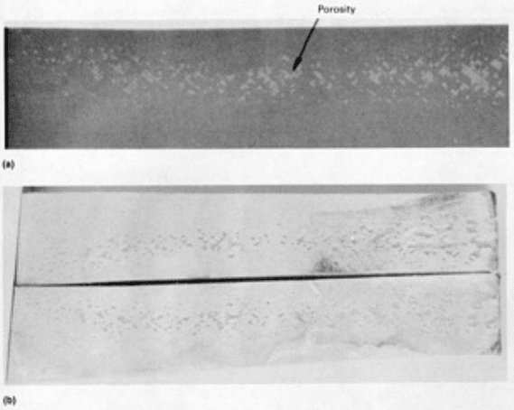
voids clustered together or in lines. The neutron radiograph shown in Fig. 4(a) confirms the presence of porosity in the
bond lines visible to the eye in Fig. 4(b). Porosity is detected equally well using conventional radiography or neutron
radiography (Fig. 5). Scattered linear and dendritic porosity is usually found in adhesives supported with a matte carrier.
Linear porosity generally occurs near the outer edge of a bonded assembly and in many cases forms a porous frame
around a bonded laminate. Porosity is usually caused by trapped volatiles and is also associated with thick (single-layer
adhesive) bond lines that did not have sufficient pressure applied during the cure cycle. The reduced bond strength in
these porous areas is directly related to its density frequency and/or severity.
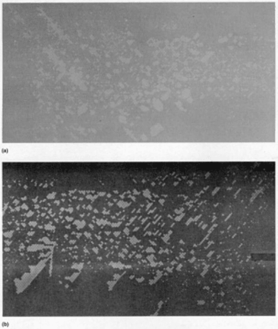
Fig. 4 Neutron radiograph (a) and visual confirmation (b) of porosity in an adhesive-bonded joint
Fig. 5 Porosity in an adhesive-bonded joint. (a) X-ray radiograph. (b) Neutron radiograph
Porous or Frothy Fillets. This condition results from too high a heat-up rate during curing. The volatiles are driven
out of the adhesive too rapidly, causing bubbling and a porous bond line, which is distinguished by the frothy fillets. This
defect is visually detectable and should also be seen in the test specimens processed within the production parts.
Lack of Fillets. Visual inspection of a bonded laminate can reveal areas where the adhesive did not form a fillet along
the edge of the bonded adherends or sheets. In long, narrow joints, a lack of fillet on both sides generally indicates a
complete void. This defect is considered serious because the high stresses near the edges of a bond joint can cause a
cracked adhesive layer due to shear or peel forces. A feeler gage can be used to determine the depth of the defect into the
joint. If the gap is too tight for a feeler gage, ultrasonic or radiographic techniques can be used to determine the depth of
the edge void.
Fractured or Gouged Fillets. These defects are detected visually. Cracked fillets are usually caused by dropping or
flexing the bond assembly. Gouges are usually made with tools such as drills or by impact with a sharp object. Fractured
and gouged bond lines are considered serious for the reasons stated earlier for lack of fillets.
Adhesive Flash. Unless precautions are taken, adhesive will flow out of the joint and form fillets plus additional
adhesive flow on mating surfaces. Although the condition is not classified as a defect, it is considered unacceptable if it
interferes with ultrasonic inspection at the edges of the bonded joint where stresses are highest.
Burned Adhesive. The adhesive may be burned during drilling operations or when bonded assemblies are cut with a
band saw. The burned adhesive is essentially overcured, causing it to become brittle and to separate from the adherend.
Also, the cohesive strength of the burned adhesive is drastically reduced. Figure 6 shows burned adhesive around hole 9
caused by improper drilling, as well as bond delamination along the edge of the panel adjacent to holes 16 through 20
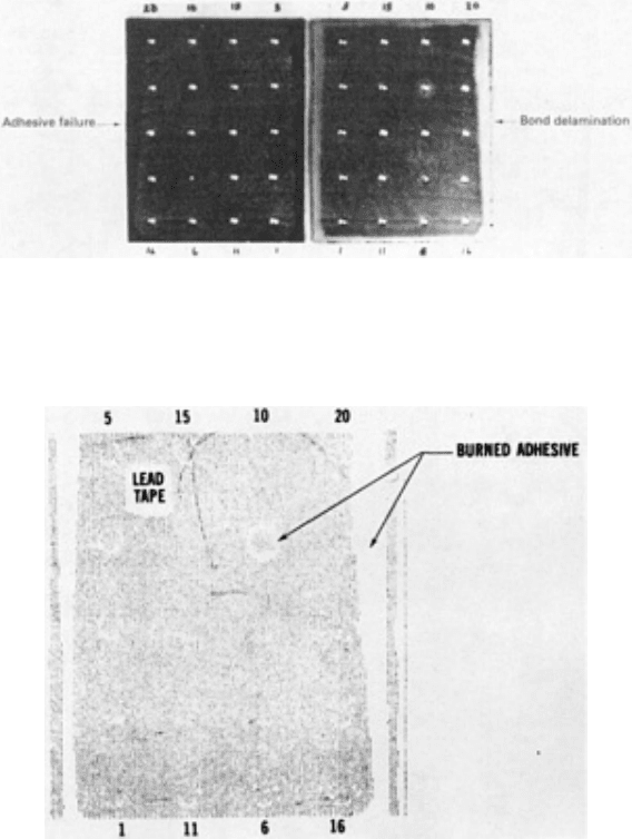
caused by band sawing. Improper drill speed or feed coupled with improper cooling can cause these types of defects. The
burned adhesive around hole 9 in Fig. 6 is detectable by ultrasonic C-scan recording methods (Fig. 7).
Fig. 6 Examples of burned adhesive
Fig. 7 Ultrasonic C-scan recording of right side of Fig. 6
Adherend Defects
Adherend defects can be detected visually and do not include the processing procedures.
Fractures (Cracks). Cracks in the adherend, whatever the cause, are not acceptable.
Double-Drilled or Irregular Holes. Some bonded assemblies may contain fastener holes. When holes are drilled
more than once, have irregular shapes, or are formed with improper tools, they are considered defects. The load-carrying
capacity of the fasteners is unevenly distributed to the adherends, resulting in high local stresses that may cause fracture
during service.
Dents, Dings, and Wrinkles. These defects are serious only when extensive in nature, as defined by applicable
acceptance criteria or specifications. They are most detrimental close to, or at, a bond joint. Dents are usually caused by
impact with blunt tools or other objects and are usually rounded depressions. Dings result from impact with sharp objects
or when an assembly is bumped at the edge. Dents or dings may cause bond line or adherend fractures. Wrinkles are
bands of distorted adherends and are usually unimportant.
Scratches and Gouges. A scratch is a long, narrow mark in the adherend caused by a sharp object. Deep scratches are
usually unacceptable, because they can create a stress raiser which may generate a metal crack during service. On the
other hand, gouges are blunt linear indentations in the adherend surface. Deep gouges, like scratches, are generally
unacceptable.
Honeycomb Sandwich Defects
The most prominent defects found or generated in honeycomb sandwich assemblies are summarized in Table 1. Adhesion
and/or cohesion defects may also occur in bonded honeycomb sandwich assemblies. The metal-to-metal closure areas for
honeycomb panels may exhibit the types of defects discussed in the preceding section. In addition, sandwich assemblies
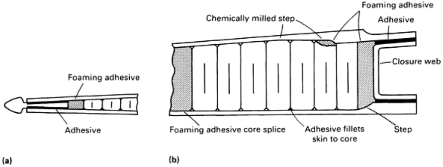
can have defects in the honeycomb core, between the core and skins, between core and closure, at chemically milled
steps, and in core splices. These bond areas are shown in Fig. 8 for a typical honeycomb assembly.
Fig. 8 Typical configuration of bonded honeycomb assembly. (a) Trailing edge. (b) Leading edge
Water in Core Cells. Upon completion of the bonded assembly, some manufacturers perform a hot-water leak test to
determine if the assembly is leakproof. If the assembly emits bubbles during the leak test, the area is marked and
subsequently repaired. To ensure that all bonded areas are inspected and that no water remains trapped in the assembly, it
is then radiographed. This is important because water can turn into ice during operational service and rupture the cells, or
it can initiate corrosion on the skin or core. Water in the core can be detected radiographically when the cells are filled to
at least 10% of the core height. Also, x-ray detection sensitivity is dependent on the sandwich skin thickness and
radiographic technique. An additional problem is the ability to determine whether the suspect area has excessive adhesive,
filler, or water. Water images usually have the same film density from cell to cell or for a group of cells, while adhesive
or filler images may vary in film density within the cells or show indications of porosity. A radiographic positive print of
moisture in honeycomb is shown in Fig. 9.

Fig. 9 Positive print from x-ray negative showing water intrusion into honeycomb cells
Crushed Core. A crushed honeycomb core may be associated with a dent in the skin or may be caused by excessive
bonding pressure on thick core sections. Crushing of the core greatly diminishes its ability to support the facing sheets.
Figure 10 shows an x-ray positive print of crushed core. Generally, crushed core is most easily detected with angled x-ray
exposures. Crushed core is defined as localized buckling of the cell walls at either face sheet, when associated with the
halo effect on a radiograph. On the other hand, for wrinkled core, the cell walls are slightly buckled or corrugated.
Radiographically, the condition appears as parallel lines in the cell walls. A wrinkled core is generally acceptable.
Fig. 10 Positive print from x-ray negative showing crushed honeycomb core
Condensed core occurs when the edge of the core is compressed laterally. Lateral compression may result from
bumping the edge of the core during handling or lay-up, or slippage of detailed parts during bonding. The condition
occurs most often near honeycomb edge closures. Figure 11 shows a positive radiograph of various degrees of condensed
core.
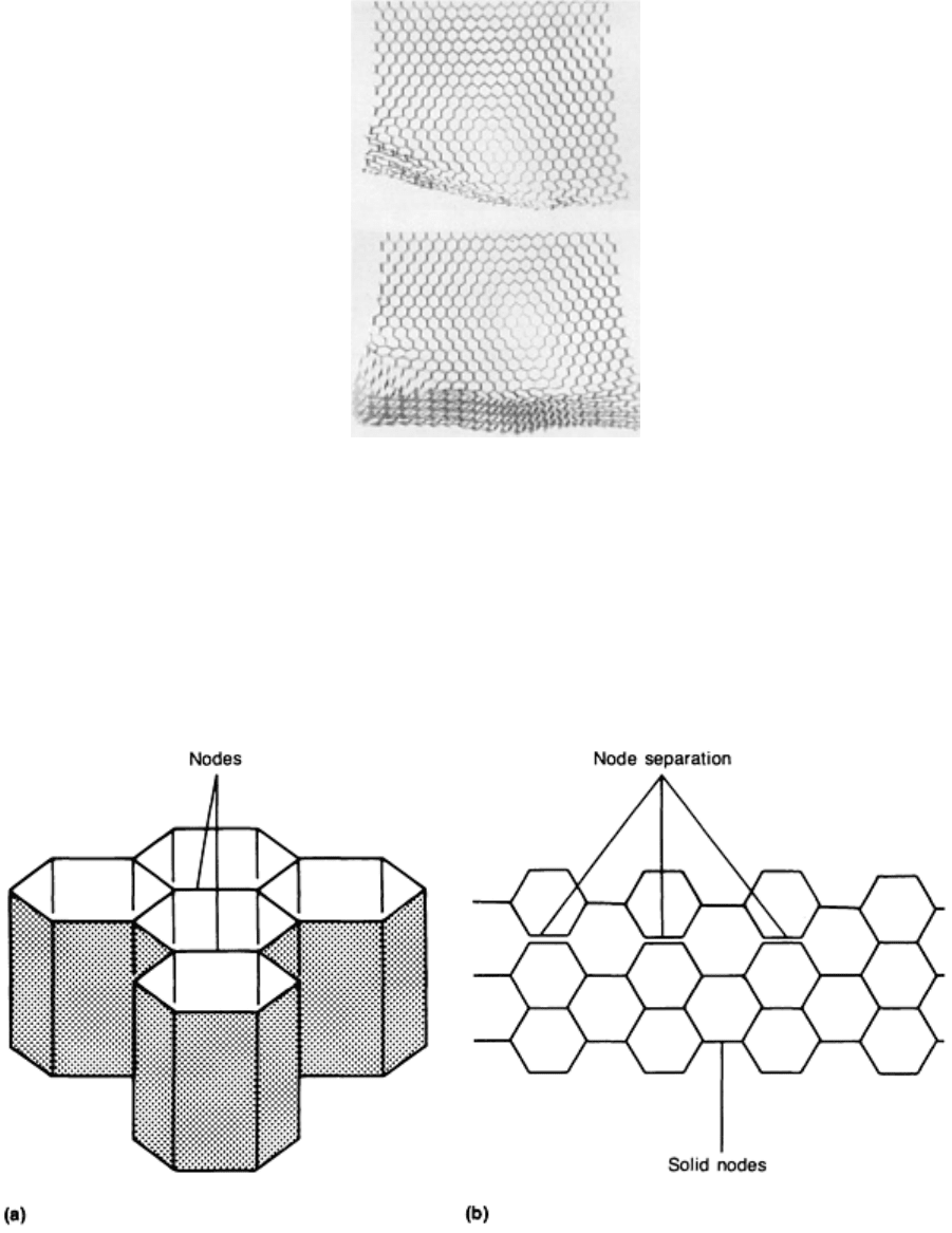
Fig. 11 Two x-ray positive radiographs showing various degrees of condensed core
Node separation results when the foil ribbons are separated at their connecting points or nodes, as shown
schematically in Fig. 12 and in the photograph in Fig. 13. Node separation usually occurs during core fabrication. It may
also result from pressure buildup in cells as a result of vacuum bag leaks or failure, which allows the pressurizing gas to
enter the assembly and core cells.
Fig. 12 Examples of honeycomb core separation. (a) Joined and solid nodes. (b) Node separation
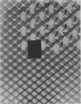
Fig. 13 Radiograph illustration of node separation
Blown core occurs as a result of a vacuum bag leak or because of a sudden change in pressure during the bonding cycle.
The pressure change produces a side loading on the cell walls that can either distort the cell walls or break the node
bonds. Radiographically, this is indicated as:
• Single-cell damage, usually appearing as round or elliptical cell walls with partial node separation
•
Multicell damage, usually appearing as a curved wave front of core ribbons that are compressed
together
The blown core condition is most likely to occur at the edge of the assembly in an area close to the external surface where
the greatest effect of sudden change in pressure occurs. This condition is most prevalent whenever there are leak paths,
such as gaps in the closure ribs to accommodate fasteners, or chemically milled steps in the skin where the core may not
fit properly. When associated with skin-to-core unbonds, the condition is detectable by pulse-echo and through
transmission ultrasonic techniques. The condition is readily detectable by radiography when the x-ray beam centerline is
parallel to the core cell walls, as shown in Fig. 14.
