ASM Metals HandBook Vol. 17 - Nondestructive Evaluation and Quality Control
Подождите немного. Документ загружается.

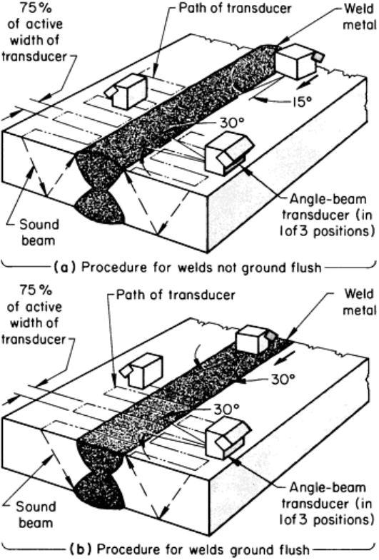
Fig. 40 Ultrasonic scanning procedures to detect longitudinal and transverse discont
inuities in welds that (a)
are not ground flush and (b) are ground flush
To detect longitudinal discontinuities in full-penetration butt and corner welds that are not ground flush, the transducer is
oscillated to the left and right in a radial motion, with an included angle of approximately 30°, while scanning
perpendicularly toward the weld, as shown in Fig. 40(a). The longitudinal movement necessary to advance the transducer
parallel to the weld should not exceed 75% of the active width of the transducer per transverse scan. The weld should be
scanned from both sides on one surface or from one side on both surfaces to ensure that nonvertically oriented flat
discontinuities are detected. This type of discontinuity can be distinguished from vertically oriented flat discontinuities
because the signal amplitudes from the two sides are different.
To detect transverse discontinuities in welds that are not ground flush, the transducer is placed on the base metal surface
at the edge of the weld. The sound beam is directed by angling the transducer approximately 15% toward the weld from
the longitudinal-weld axis, as shown in Fig. 40(a). Scanning is performed by moving the transducer along the edge of the
weld either in one direction along both sides of the weld or in opposite directions along one side of the weld.
To detect longitudinal discontinuities in welds that are ground flush, the transducer is oscillated to the left and right in a
radial motion, with an included angle of approximately 30°, while scanning across the weld as shown in Fig. 40(b). The
longitudinal movement necessary to advance the transducer parallel to the weld must not exceed 75% of the active width
of the transducer per transverse scan. When possible, the weld is scanned from one surface on two sides of the weld.
When this is not possible, the weld can be scanned from one side on two surfaces or from one side on one surface using at
least one full skip distance.
To detect transverse discontinuities in welds that are ground flush, the transducer is oscillated to the left and right in a
radial motion, with an included angle of approximately 30°, as shown in Fig. 40(b), while scanning along the top of the
weld from two opposing directions. If the width of the weld exceeds the width of the transducer, parallel scans should be
performed, with each succeeding scan overlapping the previous one by a minimum of 25% of the active width of the
transducer.
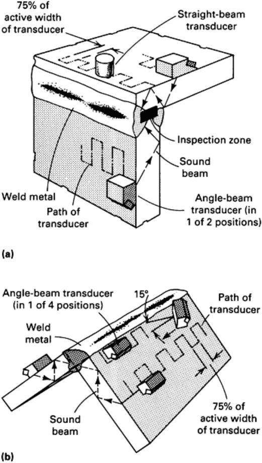
The entire volume of full-penetration welds in corner joints should be scanned with shear waves by directing the sound
beam toward, or across and along, the axis of the weld, as shown in Fig. 41. If longitudinal wave testing is utilized, the
weld is scanned by moving the transducer over the weld with overlapping paths. Each succeeding scan should overlap the
previous scan by at least 25% of the active width of the transducer.
Fig. 41 Ultrasonic scanning procedure for full-penetration groove weld (a) and double-
fillet welds (b) in corner
joints
For the detection of discontinuities in the root area in T-joints (such as lack of root fusion), the width of the inspection
zone should be limited to the thickness of the attachment member. The width of the inspection zone is located using
ultrasonics or mechanical means and marked on the test surface. Shear-wave scanning for discontinuities in the base
metal of any T-joint configuration should be performed whenever the surface opposite the attachment member is
accessible. This scanning procedure can also be applied to partial-penetration welds in T-joints.
Coverage in each direction begins from the nearest section of the joint to beyond the centerline of the weld. The angle-
beam transducer is directed at the particular area of interest and oscillated to the left and right in a radial motion, with an
included angle of approximately 30°, while scanning perpendicularly toward the inspection zone. The inspection zone
depth should be limited to the through-member-plate thickness minus 6 mm ( in.). The movement necessary to advance
the transducer parallel to the inspection zone should not exceed 75% of the active width of the transducer per
perpendicular scan.
Discontinuity Signals. Cracks and LOF discontinuities present essentially flat reflectors to the ultrasonic beam. If the
beam is perpendicular to the place of the discontinuity, the amplitude of the signal is high; but if the beam strikes the
discontinuity at an angle, most of the ultrasonic energy is reflected away from the transducer, and the reflected signal has
a small amplitude that will vary with the angle. Because both cracks and sidewall LOF discontinuities produce similar
reflected signals, they cannot be distinguished from one another by the signal amplitude or signal shape on the viewing
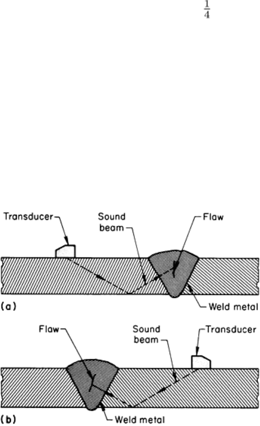
screen when scanning is done from only one side. Therefore, the weld should be inspected from two sides, as shown in
Fig. 42. If the discontinuity is vertically oriented, such as a centerline crack would be, the reflected signals received
during a scan of each side should have approximately the same amplitude. If the discontinuity is in an inclined position,
such as a sidewall LOF discontinuity would be in many joint designs, there will be an appreciable difference between the
signal amplitudes.
Fig. 42
Transducer scanning positions for distinguishing between weld metal flaws that are (a) vertically
oriented and (b) in an inclined position
A slag inclusion in a butt weld may produce a reflected signal with the same amplitude as that received from a crack or
LOF discontinuity. However, scattered ultrasonic energy produces a relatively wide and high signal; as the transducer is
manipulated around the slag inclusion, the signal height does not decrease significantly, but the edges of the signal vary.
The same shape of reflected signal should be displayed when the weld is scanned from the opposite side of the weldment.
The signals that are reflected from porosity (gas pockets) are usually small and narrow. The signal amplitude will vary if
the transducer is manipulated around the gas pocket or if the gas pocket is scanned from the opposite side of the weld.
Cluster porosity (groups of gas pockets, as shown in Fig. 27) usually produces displays with a number of small signals.
Depending on the number of gas pockets and their orientation to the ultrasonic beam, the displayed signals will be
stationary or will be connected with one another.
Lack of fusion, weld root cracks, and LOP give essentially the same type of signal on an oscilloscope screen; the reflected
signals are narrow and appear at the same location. The best way to differentiate among these flaws is to determine the
extent of the flaw in the transverse direction.
Weld undercutting is distinguishable from sidewall LOF. The signals reflected from undercutting are approximately equal
in amplitude when scanned from both sides. The signals produced by a sidewall LOF discontinuity vary considerably in
amplitude when scanned from both sides.
In many cases, a weld is made when two misaligned parts must be joined; this condition is termed weld mismatch (Fig. 23
and 24). The inspector must not confuse a signal reflected from a root crack with one reflected from the misaligned edge.
A narrow signal is usually produced when the ultrasonic beam strikes the misaligned edge. In most cases, no reflected
signal will be received if the misaligned edge is scanned from the opposite side.
Ultrasonic Inspection of Spot Welds in Thin-Gage Steel. With the development of high-frequency transducers
(12 to 20 MHz), pulse-echo ultrasonic inspection of spot welds in very thin gage sheet metal (0.58 mm, or 0.023 in.) is
now possible (Ref 1). The ultrasonic test for spot weld nugget integrity relies on an ultrasonic wave to measure the size of
the nugget. The size is in three dimensions, including thickness as well as length and breadth (or diameter for a circular
spot). The successful measurement of nugget size places several requirements on the ultrasonic wave path, wave velocity,
and wave attenuation.
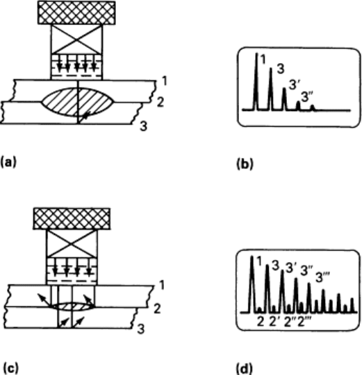
Wave Path. The first requirement is that the ultrasonic wave be in the form of a beam directed perpendicular to the
faces of the metal sheets and through the center of the nugget (Fig. 43). Two diameters of nuggets are shown: larger than
the beam and smaller than the beam.
Fig. 43 Schematic illustrating setup for the pulse-echo ultrasonic inspection of resistance-
welded spot welds.
(a) Wave paths in satisfactory weld. (b) Resulting echoes. (c) Wave paths in an unsatisfactory weld.
(d)
Resulting echoes. Source: Ref 1
In general, an ultrasonic wave will be reflected when it impinges on an interface where the density and/or the ultrasonic
velocity change. Examples are water-to-metal and metal-to-air. In Fig. 43, reflections will occur at the outer surfaces of
the two sheets and at the interface (air) between the two sheets if the nugget is small, as in Fig. 43(c). The nugget-to-
parent-metal boundary will not produce perceptible reflections, refraction, or scattering, because the changes in density
and velocity are a tenth of a percent or less, while the air-to-steel difference is more than 99.9%.
Typical oscilloscope displays showing the pulse-echo patterns for these two nugget-to-beam-diameter ratios are shown in
Fig. 43(b) and 43(d). The difference in the echo patterns permits the distinction to be made between adequate and
undersize welds.
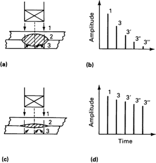
Velocity/Thickness Gaging. The beam path shown in Fig. 43(a) illustrates the situation in which the ultrasonic beam
should indicate an acceptable nugget. The beam will be reflected only at the outer surfaces (1 and 3) of the pair of sheets
as joined. To make this reflection sequence visible, the ultrasonic beam must consist of a short pulse that can reverberate
back and forth between the outer faces and produce separate echoes when viewed on an oscilloscope. The picture
observed is shown in Fig. 43(b). The pulse must be short enough to resolve the double thickness of the two joined sheets.
Similarly, the beam path shown in Fig. 43(c) illustrates the situation in which the ultrasonic beam should indicate an
undersize nugget. The beam will be reflected in the single thickness of the upper sheet around the perimeter of the nugget.
Therefore, on the oscilloscope, echoes will appear between the principal echoes arising from the portion of the beam
traversing the nugget (Fig. 43d). In terms of thickness gaging, the ultrasonic pulse in the beam must be short enough to
resolve the thickness of one layer of sheet metal.
Attenuation. The thickness of the nugget can be measured only indirectly because the thickness gaging function
(described above) can measure only the thickness between outer faces in the nugget area. The nugget itself is measured by
the effect of its grain structure on the attenuation of the ultrasonic wave in the beam. As the wave reflects back and forth
between the outer faces of the welded sheets, its amplitude is attenuated (dies out). The attenuation (rate of decay) of the
ultrasonic wave depends on the microstructure of the metal in the beam. In the spot welds under consideration, the
attenuation is caused principally by grain scattering. The grains scatter the ultrasonic energy out of the coherent beam,
causing the echoes to die away. In most metals, coarse grains scatter more strongly than fine grains.
Because a nugget is a melted and subsequently refrozen cast microstructure with coarser grains than the adjacent cold-
rolled parent metal, the nugget will scatter more strongly than the remaining parent metal. It follows that a nugget will
produce higher attenuation than the parent metal and that a thick nugget will result in higher attenuation than will a thin
nugget. Therefore, a thin nugget can be distinguished from a thick nugget by the rate of decay of the echoes in the case in
which the diameters of both nuggets are equal. Typical echoes from a thick nugget area and from a thin nugget are shown
in Fig. 44. It is clear that a trained observer could differentiate between the two welds on the basis of the decay patterns.
Given this observation, it is obvious that the pulse-echo ultrasonic method at normal incidence could perform the required
measurements on spot welds in metals with coarse-grain nuggets and fine-grain parent sheet metal.
Fig. 44
Ultrasonic thickness measurements of resistance spot weld nuggets. (a) Satisfactory weld. (b)
Resulting attenuation of the ultrasonic wave.
(c) Unsatisfactory weld. (d) Resulting wave attenuation. Source:
Ref 1
Acoustic Emission Monitoring
Acoustic emissions are impulsively generated small-amplitude elastic stress waves created by deformations in a material.
The rapid release of kinetic energy from the deformation mechanism propagates elastic waves from the source, and these
are deteced as small displacements on the surface of the specimen. The emissions indicate the onset and continuation of
deformation and can be used to locate the source of deformation through triangulation techniques. Details of the process
are available in the article "Acoustic Emission Inspection" in this Volume.
Acoustic emissions can be used to assess weld quality by monitoring during or after welding. In weldments, regions
having LOP, cracking, porosity, inclusions, or other discontinuities can be identified by detecting the acoustic emissions
originating at these regions. During welding processes, acoustic emissions are caused by many factors, including plastic
deformation, melting, friction, solidification, solid-solid phase transformations, and cracking. In some cases, the
monitoring of acoustic emissions during welding can include automatic feedback control of the welding process. In large-
scale automatic welding, the readout equipment can be conveniently located near the welder controls or in a quality-
monitoring area.
The locations of acoustic sources on a weld line can be presented in a variety of ways. One technique displays the
number of events versus distance along the weld on an oscilloscope screen or an x-y plotter. Another technique uses a
digital-line printer that gives the time of the event, its location, and its intensity. This information facilitates appraisal of
the severity of each source. Once the acoustic emission sources are graded, other NDI methods can be used to study the
discontinuity in detail.
It is sometimes difficult to achieve a good acoustic coupling between the sensor (or sensors) and the part. This is
especially true for welding processes that have a fixed arc and a moving part. For postweld acoustic emission monitoring,
a stimulus must be applied after complete cooling of the weld. This involves the application of a mechanical load or
sometimes a thermal stress to the part or structure. For the field inspection of in-service welds for cracks or other flaws,
welds are commonly subjected to stresses that just exceed the maximum stress previously experienced by the weld. The
excess stress is necessary to produce acoustic emissions due to plastic deformation at the crack tip. The application of this
stress, however, is often difficult to do and in some cases is undesirable. An alternative method that can often clearly
detect existing cracks in a weld is to cyclically load the weld at low-stress levels. The relative motions of the crack
surfaces produce frictional excitation of stress waves.
Acoustic emission monitoring for evaluation of quality and control of welding processes requires preliminary studies for
each application to establish such operating conditions as the number, location, and mounting of sensors; gain settings;
filtering; data presentation; and data interpretation. These studies normally include correlation with other nondestructive
and destructive methods of inspection. For example, the detection of tungsten inclusions from GTAW joints by acoustic
emission can also involve inclusion classification by radiography.
The postweld monitoring of weldments includes both quality control inspection during the period between the
completion of the weld and additional fabrication of the part and nondestructive inspection of in-service weldments. An
example of the former is the inspection of butt-welded plates, such as those fabricated in the building of a ship. The
following example demonstrates the feasibility of immediate postweld acoustic emission monitoring of butt-welded
plates.
Example 1: Acoustic Emission Monitoring of Butt Welds in Low-Carbon Steel Plates.
Using a dc arc welder, two low-carbon steel plates 460 mm (18 in.) wide by 610 mm (24 in.) long and 3.2 mm (0.125 in.)
thick were butt welded to form a test plate approximately 1.2 m (48 in.) long, as shown in Fig. 45. Extra precautions were
taken to produce a sound weld. After the weld metal was cool, the plate was placed in a fixture so that acoustic emission
from the weld metal could be monitored.
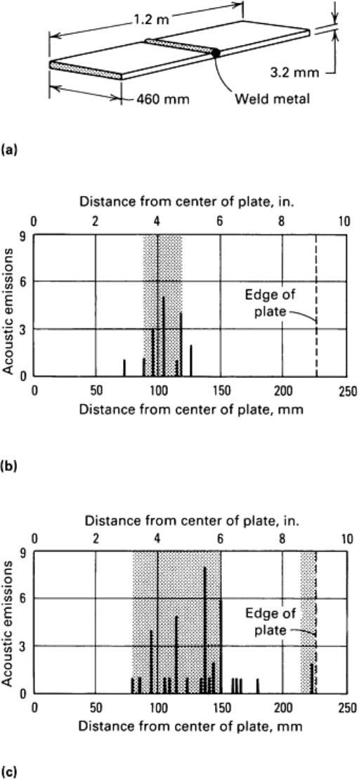
Fig. 45 Acoustic emission monitoring of butt welds in low-
carbon steel test plates. (a) Test plate. Three were
prepared; the first, with a sound weld, was used to establish conditions for acoustic emission monitoring of the
others. (b) Location and numb
er of acoustic emissions in the second test plate, which had a region of
intentional poor penetration and slag inclusions (shaded area). (c) Location and number of acoustic emissions
in the third test plate, in which flaw indications were revealed by radiographic inspection (shaded areas).
The plate was supported horizontally by a system of rubber rollers. Weights were placed on each end of the plate to hold
it firmly on the rollers. Mild bending was induced in the butt joint by raising and lowering the middle of the plate with a
hydraulic jack. Acoustic emissions were monitored during loading and unloading oscillation and while the plate was held
in a stress state, using sensors attached to the top side of the plate at each end of the weld. These emissions were used to
calibrate the oscilloscope screen and were the basis for subsequent inspections of plates having known or suspected
discontinuities in the weld metal.
The output signal of each sensor was amplified (75-dB gain), filtered (50 kHz to 1 MHz), and displayed on a dual-beam
oscilloscope. Single-sweep traces of both signals were triggered at the arrival of the first signal. These were photographed
from the dual-beam display, and successive photographs permitted documentation of the difference between the arrival
times at the two sensors for several sources. The locations of the predominant sources were then inferred.
After the preliminary experiments, a second test plate was prepared and butt welded across its entire width. The weld was
made with intentional poor penetration and slag inclusions in a region centered about 100 mm (4 in.) on one side of the
centerline of the plate, as indicated by the shaded area in Fig. 45(b). Acoustic emissions were recorded during bending
and oscillation. The location and number of acoustic emissions are given graphically in Fig. 45(b). A good correlation
existed between the tabulated source locations and the locations of known flaws.
A third test plate was prepared by making a saw cut 180 mm (7 in.) long, from one edge toward the center, along the
transverse centerline. This saw cut was repaired by welding, then monitored for acoustic emissions in the same manner as
the second test plate. Radiographic inspection of the plate revealed two regions of discontinuities in the weld, as indicated
by the shaded areas in Fig. 45(c). A region of very poor penetration between 130 and 150 mm (5 and 6 in.) from the
longitudinal centerline of the plate is shown by the darker shaded area in Fig. 45(c). This corresponds to the large number
of acoustic emissions occurring in the region. Also shown in Fig. 45(c) are other regions from which acoustic emissions
originated, indicating discontinuities in the weld metal. From the results obtained on these test plates, it was concluded
that it is feasible to use acoustic emission monitoring as a method of assessing the structural integrity of butt-welded
joints.
In-Service Monitoring. One application of in-service acoustic emission monitoring of welds involved the locating of
defective or deteriorated welds in buried pipelines. Gas distribution pipelines that had been in service for many years
needed inspections for structural integrity, especially on oxyacetylene welds. Although the location of the buried pipe was
known, the locations of the welds were not. In preliminary studies, it was found that acoustic emission signals from weld
discontinuities would propagate several hundred feet down the pipe. Therefore, a very efficient method of locating the
defective welds was devised. The loading stimulus, an extra heavy vehicle moving slowly along the surface above the
pipe, induced bending stresses that were sufficient to cause weld discontinuities to emit. Sensors were placed on either
side of the suspect weld, and the signals reaching the sensors were monitored with portable equipment. By comparing the
time required for the emissions to reach each pair of sensors and by comparing the intensities of the signals, the locations
of the defective weld were determined. The welded joints were then excavated, and the welds were further inspected or
repaired.
Monitoring During Welding. Arc-welding processes are inherently ultrasonically noisy--particularly so in continuous
high-frequency welding. However, the acoustic emissions detected during proper welding without discontinuity creation
have steady characteristics. When cracking, excessive slag inclusion, or a significant change in the weld conditions
occurs, the acoustic emission levels change correspondingly. Therefore, online monitoring during welding gives
immediate indication of variations in the quality of the weld. Cold cracking can be detected by monitoring the welded
structure for minutes, or even hours, after welding.
Acoustic emissions result from multiple causes during resistance spot welding. The making of a resistance spot weld
consists of setdown of the electrodes, squeeze, current flow, hold time, and lift off. Many acoustic emissions are produced
during these various steps. The most commonly observed signals are shown schematically in Fig. 46. The ultrasonic noise
during setdown and squeeze can be related to the conditions of the electrodes and the surface of the parts. The large, but
brief, signal at current initiation can be related to the initial resistance and the cleanliness of the parts. During current
flow, acoustic emission results from plastic deformation, friction, melting, and expulsions. The signals associated with
expulsion (spitting and flashing) are generally large in amplitude and can be easily distinguished from the rest of the
emissions associated with nugget formation. When current flow ceases, some materials exhibit appreciable solidification
noise that can be related to nugget size and inclusions. As the nugget cools in the hold period, acoustic emissions can
result from solid-solid phase transformations and cracking. Finally, as the electrode is lifted, noise is produced by the
separation of the electrode from the part. This noise, or signal, can be related to the size of the nugget as well as to the
visual appearance of the weld.
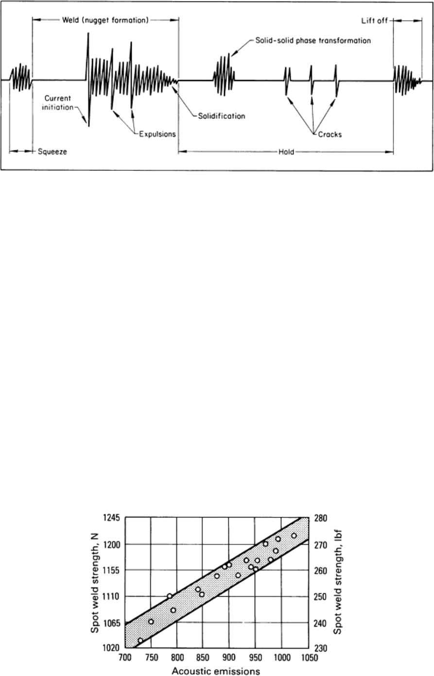
Fig. 46 Schematic showing typical acoustic emission signals obt
ained during various stages of resistance spot
welding
Any measure of the cumulative acoustic emissions during resistance spot welding cannot be expected to relate clearly to
weld quality. On the other hand, by using both time discrimination and multiple detection levels, the various segments of
acoustic emissions can be separately measured and related to various indicators of quality. Commercial instrumentation is
available that is capable of separately monitoring several of the acoustic emission segments. For example, the expulsion
count, phase-transformation count, and cracking count can be monitored and recorded for each resistance spot weld,
giving a permanent record of quality. In the following example, a number of acoustic emissions during martensitic phase
transformation were found to relate to the strength of the resistance spot weld.
Example 2: Determination of Strength of Resistance Spot Welds by Acoustic Emission
Monitoring.
Twenty carbon steel coupons were spot welded at identical settings of heat and weld cycles in a 75-kVA ac spot welder.
An acoustic emission sensor was attached to the lower electrode. The acoustic emission monitor was gated to begin 120
ms after the current ceased and to stop 240 ms later. Within that time interval, martensitic phase transformation occurred
as the nugget cooled. Because the total volume of material experiencing the transformation is related to both the nugget
size and the area of diffusion bonding, the acoustic emissions during the phase transformation are related to the strength
of the weld. The specimens were pulled to failure in tension shear, and the ultimate strength was recorded. The results are
shown in Fig. 47. The tests indicated that a 10% variation in weld strength corresponded to about a 30% change in
acoustic emissions.
Fig. 47
Relation of strength of resistance spot welds in carbon steel coupons to number of acoustic emissions

during the martensitic phase transformation
Leak Testing
Welded structures are leak tested to measure the integrity of the structure for containing gases, fluids, semisolids, and
solids and for maintaining pressures and vacuums. The more common leak-testing methods used are (in order of
increasing sensitivity):
• Odor from tracer gas
• Pressure change
• Pressurized liquid (generally water) and visual observation
• Pressurized gas using a leak detection solution
• Tracer gas using thermal leak detectors
• Helium using a mass spectrometer during pressure and vacuum tests
Other methods less frequently used are acoustical detection of gas flow through a leak and use of radioactive tracer gas.
Detailed descriptions of the various methods used are presented in the article "Leak Testing" in this Volume.
Weld flaws that contribute to leakage of a structure are porosity, LOF or LOP, and cracks. Cracks are of particular
concern because they may propagate when the structure is proof tested or otherwise tested for structural integrity.
Therefore, it is preferred that leak testing be done after completion of the structural tests.
Selection of a leak testing method depends on the environment in which the structure is used and the potential danger and
economic impact involved in the event of a service failure. The acceptance criteria should include a numerical expression
of the allowable leak rate; the frequently used expression "shall be free from leaks" is meaningless.
Eddy Current and Electric Current Perturbation Inspection
Eddy current inspection is based on the principles of electromagnetic induction and is used to identify or to
differentiate between a wide variety of physical, structural, amd metallurgical conditions in electrically conductive
ferromagnetic and nonferromagnetic metals. Normally, eddy current inspection is used only on thin-wall welded pipe and
tubing for the detection of longitudinal-weld discontinuities, such as open welds, weld cracks, and porosity. The
application of this method to tubular goods is discussed in the articles "Eddy Current Inspection," "Tubular Products," and
"Boilers and Pressure Vessels" in this Volume.
The electric current perturbation method consists of establishing an electric current flow in the part to he
inspected (usually by means of an induction coil) and detecting the magnetic field associated with perturbations in the
current flow around defects by using a separate magnetic field sensor (Ref 7). This technique is applicable to the detection
of both very small surface cracks as well as subsurface cracks in both high- and low-conductivity, nonferromagnetic
materials, such as titanium and aluminum alloys. The principles, equipment, and applications associated with this method
are outlined in the article "Electric Current Perturbation NDE" in this Volume.
References cited in this section
1.
T.M. Mansour, Ultrasonic Inspection of Spot Welds in Thin-Gage Steel, Mater. Eval.,
Vol 46 (No. 5), April
1988, p 650-658
2.
P. Kapranos and R. Priestner, NDE of Diffusion Bonds, Met. Mater., Vol 3 (No. 4), April 1987, p 194-198
3.
P.G. Partridge, "Diffusion Bonding of Metals," Advisory Group for Aerospace Research and Development
(NATO), Aug 1987, p 5.1-5.23
4.
G. Tober and S. Elze, "Ultrasonic Testing Techniques for Diffusion-
Bonded Titanium Components,"
Advisory Group for Aerospace Research and Development (NATO), July 1986, p 11.1-11.10
5.
Diffusion Welding and Brazing, Vol 3, 7th ed., Welding Handbook, American Welding Society, 1980, p 311-
335
