ASM Metals HandBook Vol. 17 - Nondestructive Evaluation and Quality Control
Подождите немного. Документ загружается.

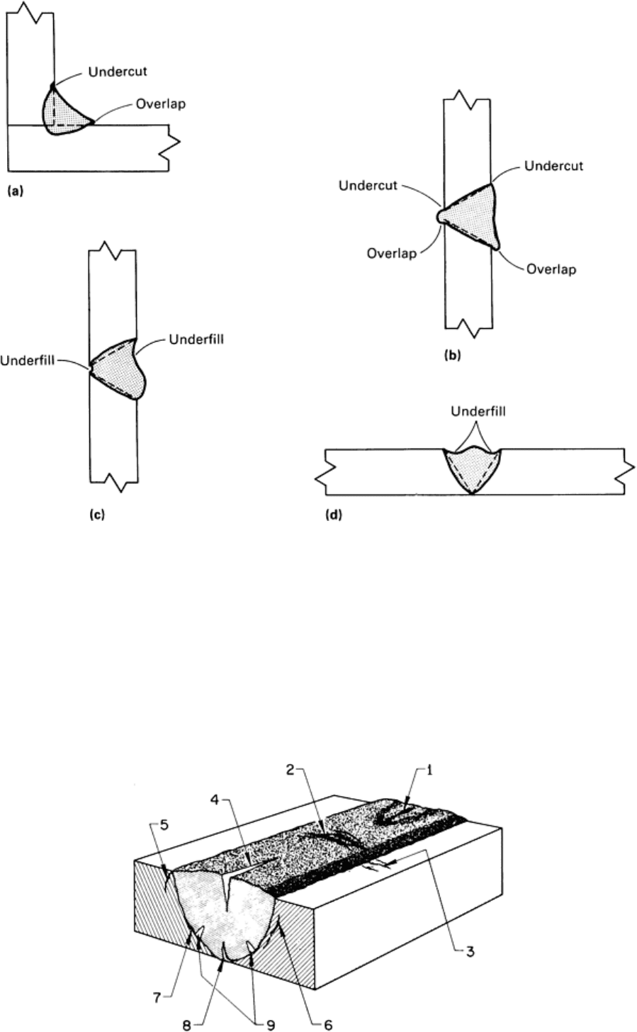
Fig. 5
Weld discontinuities affecting weld shape and contour. (a) Undercut and overlapping in a fillet weld. (b)
Undercut and overlapping in a groove weld. (c) and (d) Underfill in groove welds
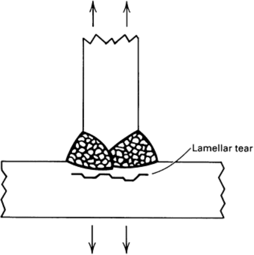
Cracks can occur in a wide variety of shapes and types and can be located in numerous positions in and around a welded
joint (Fig. 6). Cracks associated with welding can be categorized according to whether they originate in the weld itself or
in the base metal. Four types commonly occur in the weld metal: transverse, longitudinal, crater, and hat cracks. Base
metal cracks can be divided into seven categories: transverse cracks, underbead cracks, toe cracks, root cracks, lamellar
tearing, delaminations, and fusion-line cracks.
Fig. 6 Identification of cr
acks according to location in weld and base metal. 1, crater crack in weld metal; 2,
transverse crack in weld metal; 3, transverse crack in HAZ; 4, longitudinal crack in weld metal; 5, toe crack in
base metal; 6, underbead crack in base metal; 7, fusion-li
ne crack; 8, root crack in weld metal; 9, hat cracks in
weld metal
Weld metal cracks and base metal cracks that extend to the surface can be detected by liquid penetrant and magnetic
particle inspection. Magnetic particle inspection can also detect subsurface cracks, depending on their size, shape, and
proximity to the surface. Although the orientation of a crack with respect to the direction of the radiation beam is the
dominant factor in determining the ability of radiography to detect the crack, differences in composition between the base
metal and the weld metal may create shadows to hide a crack that otherwise might be visible. Ultrasonic inspection is
generally effective in detecting most cracks in the weld zone.
Transverse cracks in weld metal (No. 2, Fig. 6) are formed when the predominant contraction stresses are in the
direction of the weld axis. They can be hot cracks, which separate intergranularly as the result of hot shortness or
localized planar shrinkage, or they can be transgranular separations produced by stresses exceeding the strength of the
material. Transverse cracks lie in a plane normal to the axis of the weld and are usually open to the surface. They usually
extend across the entire face of the weld and sometimes propagate into the base metal.
Transverse cracks in base metal (No. 3, Fig. 6) occur on the surface in or near the HAZ. They are the result of the high
residual stresses induced by thermal cycling during welding. High hardness, excessive restraint, and the presence of
hydrogen promote their formation. Such cracks propagate into the weld or beyond the HAZ into the base metal as far as is
needed to relieve the residual stresses.
Underbead cracks (No. 6, Fig. 6) are similar to transverse cracks in that they form in the HAZ because of high
hardness, excessive restraint, and the presence of hydrogen. Their orientation follows the contour of the HAZ.
Longitudinal cracks (No. 4, Fig. 6) may exist in three forms, depending on their positions in the weld. Check cracks
are open to the surface and extend only partway through the weld. Root cracks extend from the root to some point within
the weld. Full centerline cracks may extend from the root to the face of the weld metal.
Check cracks are caused either by high contraction stresses in the final passes applied to a weld joint or by a hot-cracking
mechanism.
Root cracks are the most common form of longitudinal weld metal crack because of the relatively small size of the root
pass. If such cracks are not removed, they can propagate through the weld as subsequent passes are applied. This is the
usual mechanism by which full centerline cracks are formed.
Centerline cracks may occur at either high or low temperatures. At low temperatures, cracking is generally the result of
poor fit-up, overly rigid fit-up, or a small ratio of weld metal to base metal.
All three types of longitudinal cracks are usually oriented perpendicular to the weld face and run along the plane that
bisects the welded joint. Seldom are they open at the edge of the joint face, because this requires a fillet weld with an
extremely convex bead.
Crater cracks (No. 1, Fig. 6) are related to centerline cracks. As the name implies, crater cracks occur in the weld crater
formed at the end of a welding pass. Generally, this type of crack is caused by failure to fill the crater before breaking the
arc. When this happens, the outer edges of the crater cool rapidly, producing stresses sufficient to crack the interior of the
crater. This type of crack may be oriented longitudinally or transversely or may occur as a number of intersecting cracks
forming the shape of a star. Longitudinal crater cracks can propagate along the axis of the weld to form a centerline crack.
In addition, such cracks may propagate upward through the weld if they are not removed before subsequent passes are
applied.
Hat cracks (No. 9, Fig. 6) derive their name from the shape of the weld cross section with which they are usually
associated. This type of weld flares out near the weld face, resembling an inverted top hat. Hat cracks are the result of
excessive voltage or welding speed. The cracks are located about halfway up through the weld and extend into the weld
metal from the fusion line of the joint.
Toe and root cracks (No. 5 and 8, Fig. 6) can occur at the notches present at notch locations in the weld when high
residual stresses are present. Both toe and root cracks propagate through the brittle HAZ before they are arrested in more
ductile regions of the base metal. Characteristically, they are oriented almost perpendicular to the base metal surface and
run parallel to the weld axis.
Lamellar tearing is the phenomenon that occurs in T-joints that are fillet welded on both sides. This condition, which
occurs in the base metal or HAZ of restrained weld joints, is characterized by a steplike crack parallel to the rolling plane.
The crack originates internally because of tensile strains produced by the contraction of the weld metal and the
surrounding HAZ during cooling. Figure 7 shows a typical condition.
Fig. 7 Lamellar tear caused by thermal contraction strain
Fusion-line cracks (No. 7, Fig. 6) can be classified as either weld metal cracks or base metal cracks because they occur
along the fusion line between the two. There are no limitations as to where along the fusion line these cracks can occur or
how far around the weld they can extend.
Discontinuities Associated With Specialized Welding Processes
The preceding section has dealt mainly with the discontinuities common to conventional arc-welding processes. In
addition, there are certain more specialized welding methods that may have discontinuities unique to them. These
methods include electron beam, plasma arc, electroslag, friction, and resistance welding. In general, the types of
discontinuities associated with these processes are the same as those associated with conventional arc welding; however,
because of the nature of the processes and the joint configurations involved, such discontinuities may be oriented
differently from those previously described, or they may present particular problems of location and evaluation.
Electron Beam Welding
In electron beam welding, as in all other welding processes, weld discontinuities can be divided into two major
categories:
• Those that occur at, or are open to, the surface
• Those that occur below the surface

Surface flaws include undercut, mismatch, underfill, reinforcement, cracks, missed seams, and LOP. Subsurface flaws
include porosity, massive voids, bursts, cracks, missed seams, and LOP. Figure 8 shows poor welds containing these
flaws, and a good weld with none of them.
Fig. 8 Electron beam welds showing flaws that can occur in poor welds and the absence of flaws in a g
ood weld
with reinforcement
Surface discontinuities such as undercut, mismatch, reinforcement, and underfill are macroscopic discontinuities
related to the contour of the weld bead or the joint. As such, they are readily detected visually or dimensionally. Surface
discontinuities such as cracks are usually detected visually using liquid penetrant inspection or using magnetic particle
inspection if the material is ferromagnetic.
When liquid penetrants are used to inspect a weld for surface discontinuities such as cracks, missed seams, and LOP, the
surface to be inspected must be clean and the layers of metal smeared from machining or peened from grit- or
sandblasting must be removed. Generally, some type of etching or pickling treatment works well, but the possibility of
hydrogen pickup from the treatment must be considered.
Occasionally, special inspection procedures must be employed to detect some types of surface discontinuities. Missed
seams and LOP are often difficult to detect because they are frequently associated with complex weld joints that prevent
direct viewing of the affected surface.
Because of this difficulty, missed seams are often detected using a visual witness-line procedure, in which equally spaced
parallel lines are scribed on both sides of the unwelded joint at the crown and root surfaces. Missed seams, which result
from misalignment of the electron beam with the joint such that the fusion zone fails to encompass the entire joint, are
detected by observing the number of witness lines remaining on either side of the weld bead. By establishing the
relationship between the width of the fusion zone and the spacing of the witness lines, reasonably accurate criteria for
determining whether the joint has been contained within the weld path (and therefore whether missed seams are present)
can be developed.
Lack of penetration discontinuities occur when the fusion zone fails to penetrate through the entire joint thickness,
resulting in an unbonded area near the root of the joint. These discontinuities are best detected by etching the root surface
and observing the macroscopic shape and width of the fusion zone for full and even penetration.
An alternative method for inspecting complete weld penetration is that of immersion pulse-echo ultrasonic testing. The
planet gear carrier assembly shown in Fig. 9(a) consists of three decks (plates) and eight curved spacer sections. The
assembly, which is made from SAE 15B22M boron-treated structural steel, is held together by 16 welds. Weld integrity is
monitored by ultrasonic methods.
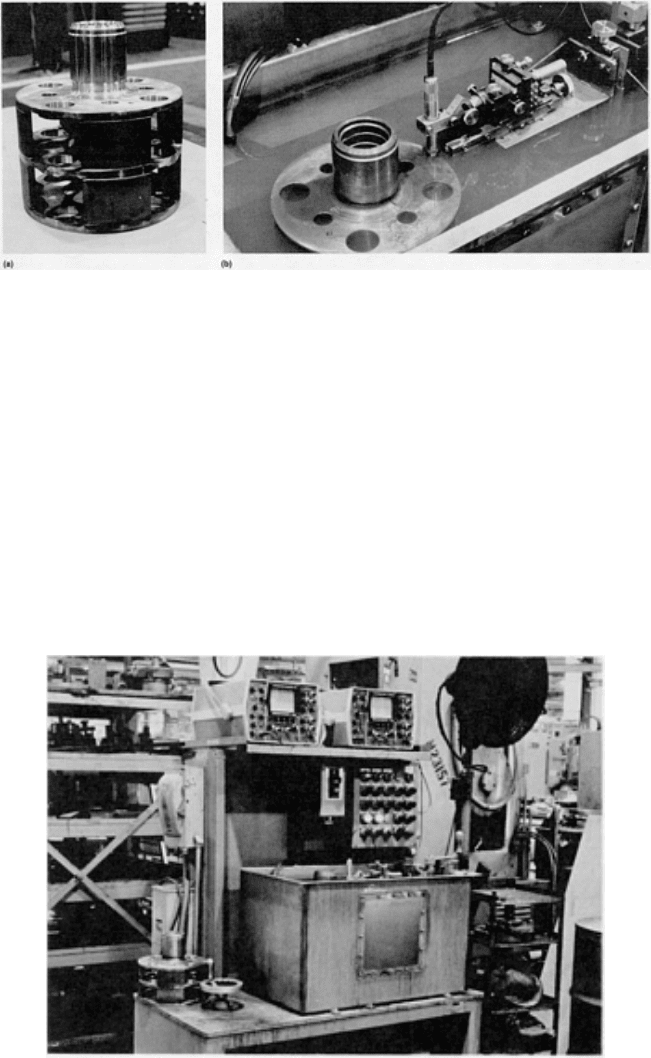
Fig. 9
Planet gear carrier assembly (a) showing the four welds in one stock that connect the three decks. The
top and top-center welds are tested by the top ultrasonic transducer, and the bottom and bottom-
center welds
are inspected by the bottom transducer. (b) Close-
up of upper transducer in position to test the welds.
Courtesy of John M. St. John, Caterpillar, Inc.
The parts are mounted on a turntable on a locating fixture so that the welds along the outside diameter are accessible. Two
transducers, located above and below the assembly, are used. Figure 9(b) shows the upper transducer in position to test
the welds. An overall view of the tank, turntable, controls, and reject/accept light panel is shown in Fig. 10. The use of
such a system involves little downtime and enables a high quality level to be maintained. More information on ultrasonic
test methods is presented later in this article.
Fig. 10 Overall view of the ultrasonic unit used to test the electron beam welded assembly shown in Fig. 9
.
Courtesy of John M. St. John, Caterpillar, Inc.
Subsurface discontinuities are generally considerably more difficult to detect than surface discontinuities because
observation is indirect. The two most reliable and widely used NDI methods are radiography and ultrasonics.
Volume-type discontinuities such as porosity, voids, and bursts are detected by radiographic inspection, provided their
cross sections presented to the radiating beam exceed 1 to 2% of the beam path in the metal. Discontinuities that present
extremely thin cross sections to the beam path, such as cracks, missed seams, and LOP, are detectable with x-rays only if
they are viewed from the end along their planar dimensions.

Ultrasonic inspection can detect most volume discontinuities as well as planar discontinuities. Planar discontinuities are
best detected normal to the plane of the discontinuities, but missed seams and LOP often appear as continuous porosity
when viewed looking down from the crown to the root of the weld in the plane of the discontinuity.
Because of the inherent dependence of both radiographic and ultrasonic inspection on the shape and orientation of flaws
and because each of the two methods can generally detect those flaws that the other misses, it is most advisable to
complement one method with the other. Furthermore, to increase the likelihood of properly viewing a flaw, one of the
methods should be employed in at least two (preferably perpendicular) directions.
Plasma Arc Welding
Discontinuities that occur in plasma arc welds include both surface and subsurface types, as shown in Fig. 11.
Fig. 11
Plasma arc welds showing flaws that can occur in poor welds and the absence of flaws in good
reinforced weld
Surface discontinuities such as irregular reinforcement, underfill, undercut, and mismatch that are associated with
weld bead contour and joint alignment are easily detected visually or dimensionally. Lack of penetration is also detected
visually through the absence of a root bead. Weld cracks that are open to the surface are detected with liquid penetrants.
Surface contamination, which results from insufficient shielding-gas coverage, is detected by the severe discoloration of
the weld bead or adjacent HAZ.
Subsurface discontinuities are generally more prevalent in manual than in automatic plasma arc welding and are
detected primarily by radiographic or ultrasonic inspection.
Porosity is by far the most commonly encountered discontinuity. Radiographic inspection is limited to detecting pores
greater than approximately 1 to 2% of the joint thickness. Visibility is greater if both the crown and root beads are
machined flush. Ultrasonic inspection can detect porosity if the joint is machined flush and joint thickness exceeds
approximately 1.3 mm (0.050 in.).
Tunneling, as shown in Fig. 11, is a severe void along the boundary of the fusion zone and the HAZ. This discontinuity
results from a combination of torch alignment and welding conditions (particularly travel speed). Tunneling is readily
detectable by radiographic inspection.
Lack of fusion discontinuities occur in either single-pass or multiple-pass repair welds (Fig. 11). These discontinuities
result from insufficient heat input to permit complete fusion of a particular weld bead to the part. Incomplete fusion can
be detected by radiographic or ultrasonic inspection. Depending on the orientation of the discontinuity, one method may
have an advantage over the other, so both should be used for optimum inspection.
Subsurface weld cracks, regardless of their cause, are detectable by radiographic and ultrasonic inspection.
Subsurface contamination in plasma arc welding results when copper from the torch nozzle is expelled into the weld. This
is caused by excessive heat, usually produced in manual repair welding when the torch nozzle is placed too close to the
weld, particularly in a groove. The resulting contamination, which may be detrimental, is undetectable by conventional
NDI methods. The only way of detecting copper contamination is by alerting the operator to watch for copper expulsion,
which then must be machined out.
Electroslag Welding
Electroslag welding involves the use of copper dams over the open surfaces of a butt joint to hold the molten metal and
the slag layer as the joint is built up vertically. Wire is fed into the slag layer continuously and is melted by the heat
generated as current passes through the highly resistant slag layer.
Generally, electroslag welds are inspected with the same nondestructive examination (NDE) methods as other heavy-
section welds. With the exception of procedure qualification, all testing is nondestructive because of the sizes used.
Techniques such as radiography and ultrasonic inspection are most often used, while visual, magnetic particle, and liquid
penetrant testing are used also. Internal defects are generally more serious. Radiography and ultrasonic tests are the best
methods for locating internal discontinuities.
Because of the nature of the process, LOF is rare. If fusion is achieved on external material edges, then fusion is generally
complete throughout. Cracking may occur either in the weld or the HAZ. Porosity may either take the form of a rounded
or a piped shape; the latter is often called wormhole porosity. Ultrasonic inspection is probably the quickest single method
for inspecting any large weldment. If defects should occur, they appear as porosity or centerline cracking. Ultrasonic
inspection is effective for locating either type of defect; however, only well-qualified personnel should set up the
equipment and interpret the test results.
Electroslag welding results in large dendritic grain sizes because of the slow cooling rate. Inexperienced personnel often
use high sensitivity and actually pick up the large coarse grains; when such welds are sectioned, usually no defects are
present. Inspectors must learn to use low sensitivity to obtain good results when inspecting electroslag welds. Magnetic
particle inspection is not a particularly good inspection method, because the areas examined by this technique are
primarily surface or near surface. This is only a small percentage of the total weld; the only useful information is either
checking the ends for craters, cracks, or centerline cracking or possibly for lack of edge fusion on the weld faces. Usually,
a visual examination gives the same result unless the defect is subsurface. Visual examinations are only effective for
surface defects, which are not common in this process.
Friction Welding
If impurities are properly dispelled during upsetting, friction or inertia welds are generally free of voids and inclusions.
Incomplete center fusion can occur when flywheel speed is too low, when the amount of upset is insufficient, or when
mating surfaces are concave. Tearing in the HAZ can be caused by low flywheel speed or excessive flywheel size. Cracks
can occur when materials that are prone to hot shortness are joined. The penetration of a split between the extruded flash
into the workpiece cross section is most prevalent during the welding of thin-wall tubing using improper conditions that
do not allow for sufficient material upset.
The area where LOF generally occurs is at or near the center of the weld cross section. Because this is a subsurface
discontinuity, detection is limited to radiographic or ultrasonic inspection; ultrasonic inspection is more practical. The
longitudinal wave test (either manual-contact or immersion method) with beam propagation perpendicular to the area of
LOF gives the most reliable results. This test can be performed as long as one end of the workpiece is accessible to the
transducer.
Penetration of the split between the extruded flash on the outer surface of a tube is readily detected by liquid penetrant or
magnetic particle inspection after the flash has been removed by machining. A split between the weld flash on the inner
surface of the tube can be detected by ultrasonic inspection using the angle-beam technique with manual contact of the
transducer to the outside surface of the tube. The transducer contacts the tube so that the sound propagates along the
longitudinal axis of the tube through the weldment.
Resistance Welding
Resistance welding encompasses spot, seam, and projection welding, each of which involves the joining of metals by
passing current from one side of the joint to the other. The types of discontinuities found in resistance welds include
porosity, LOF, and cracks. Porosity will generally be found on the centerline of the weld nugget. Lack of fusion may also
be manifested as a centerline cavity. Either of these can be caused by overheating, inadequate pressure, premature release
of pressure, or late application of pressure. Cracks may be induced by overheating, removal of pressure before weld
quenching is completed, improper loading, poor joint fit-up, or expulsion of excess metal from the weld.
Weld Appearance. On the surface of a resistance spot welded assembly, the weld spot should be uniform in shape and
relatively smooth, and it should be free of surface fusion, deep electrode indentations, electrode deposits, pits, cracks,
sheet separation, abnormal discoloration around the weld, or other conditions indicating improper maintenance of
electrodes or functioning of equipment. However, surface appearance is not always a good indicator of spot weld quality,
because shunting and other causes of insufficient heating or incomplete penetration usually leave no visible effects on the
workpiece.
The common practice for monitoring spot weld quality in manufacturing operations is the teardown method augmented
with pry testing and visual inspection (Ref 1). In visual inspection, the operator uses the physical features of the weld
surface, such as coloration, indentation, and smoothness, for assessing the quality of the weld. In pry testing, a wedge-
shaped tool is inserted between the metal sheets next to the accessible welds, and a prying action is performed to see if the
sheets will separate in the weld zone. The teardown method consists of physically tearing apart the welded members with
hammers and chisels to determine the presence and size adequacy of fused metal nuggets at the spot weld site. The
specifications require that the parent metal be torn and that the weld nugget remain intact. The destructiveness and/or
inadequacy of these common inspection methods has long been recognized, and as a result, nondestructive methods have
been extensively studied. The pulse-echo ultrasonic inspection of spot welds is now feasible and is discussed in the
section "Ultrasonic Inspection" in this article. The use of acoustic emission is also discussed below.
Diffusion Bonding (Ref 2, 3, 4, 5)
Diffusion bonding is a metal joining process that requires the application of controlled pressures at elevated temperatures
and usually a protective atmosphere to prevent oxidation. No melting and only limited macroscopic deformation or
relative motion between the faying surfaces of the parts occur during bonding. As such, the principal mechanism for joint
formation is solid-state diffusion. A diffusion aid (filler metal) may or may not be used. Terms that are also frequently
used to describe the process include diffusion welding, solid-state bonding, pressure bonding, isostatic bonding, and hot
press bonding. Diffusion bonding has the advantage of producing a product finished to size, with joint efficiencies
approaching 100%. Details of the process are given in the article "Fundamentals of Diffusion Bonding" in Welding,
Brazing, and Soldering, Volume 6 of the ASM Handbook.
Discontinuities in Diffusion Bonds. In the case of fusion welds, the detection of discontinuities less than 1 mm
(0.04 in.) in size is not generally expected. In diffusion bonding, in which no major lack of bonding occurs, individual
discontinuities may be only micrometers in size. To understand how discontinuities form in diffusion-bonded structures, it
is first necessary to consider the principles of the process.
As illustrated in Fig. 12, metal surfaces have several general characteristics:
• Roughness
• An oxidized or otherwise chemically reacted and adherent layer
• Other randomly distributed solid or liquid products such as oil, grease, and dirt
• Adsorbed gas, moisture, or both
Because of these characteristics, two necessary conditions that must be met before a satisfactory diffusion bond can be
made are:
• Mechanical intimacy of metal-to-metal contact must be achieved
• Interfering surface contaminants must be disrupted and dispersed t
o permit metallic bonding to occur
(solvent cleaning and inert gas atmospheres can reduce or eliminate problems associated with surface
contamination and oxide formation, respectively)
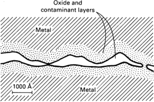
Fig. 12 Characteristics of a metal surface showing roughness and contaminants present. Source: Ref 5
For a given set of processing parameters, surface roughness is probably the most important variable influencing the
quality of diffusion-bonded joints. The size of the discontinuities (voids) is principally determined by the scale of
roughness of the surfaces being bonded. The degree of surface roughness is dependent on the material and
fabrication/machining technique used. It has been shown that bonding becomes easier with finer surface roughness prior
to bonding. Figure 13 compares the surface roughness values produced by a variety of fabrication methods. More detailed
information on surface roughness can be found in the article "Surface Finish and Surface Integrity" in Machining,
Volume 16 of ASM Handbook, formerly 9th Edition Metals Handbook.
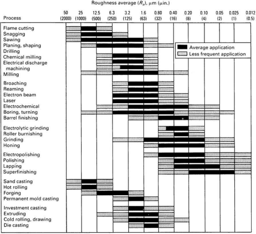
Fig. 13 Surface roughness produced by common productio
n methods. The ranges shown are typical of the
processes listed. Higher or lower values can be obtained under special conditions.
The mechanism of bond formation in diffusion bonding is believed to be the deformation of the surface roughness in
order to cause metal-to-metal contact at asperities, followed by the removal of interfacial voids and cracks by diffusional
and creep processes. For conventional diffusion bonding without a diffusion aid, the three-stage mechanistic model shown
in Fig. 14 describes bond formation. In the first stage, deformation of the contacting asperities occurs primarily by
yielding and by creep deformation mechanisms to produce intimate contact over a large fraction of the interfacial area. At
the end of this stage, the joint is essentially a grain boundary at the areas of contact with voids between these areas.
During the second stage, diffusion becomes more important than deformation, and many of the voids disappear as the
grain-boundary diffusion of atoms continues. Simultaneously, the interfacial grain boundary migrates to an equilibrium
configuration away from the original plane of the joint, leaving many of the remaining voids within the grains. In the third
stage, the remaining voids are eliminated by the volume diffusion of atoms to the void surface (equivalent to diffusion of
vacancies away from the void). Successful completion of stage three is dependent on proper surface processing and joint
processing.
