ASM Metals HandBook Vol. 17 - Nondestructive Evaluation and Quality Control
Подождите немного. Документ загружается.

Laps (Fig. 5d) are folds of metal that have been rolled or otherwise worked against the surface but that have not been
fused into sound metal.
Pits (Fig. 5e) are depressions resulting from the removal of foreign material rolled into the surface during manufacture.
Plug scores (Fig. 5f) are internal longitudinal grooves, usually caused by hard pieces of metal adhering to the mandrel,
or plug, during plug rolling.
Rolled-in slugs (Fig. 5g) are foreign metallic bodies rolled into the metal surface, usually not fused.
Scabs (Fig. 5h) are flaws in the form of a shell or veneer, generally attached to the surface by sound metal. Usually,
scabs originate as ingot flaws.
Seams (Fig. 5j) are crevices in rolled metal that have been closed by rolling or other work but have not been fused into
sound metal.
Ultrasonic inspection is probably the method most commonly used on seamless tubular products, which range from
3.2 to 660 mm ( to 26 in.) in diameter and from 0.25 to 64 mm (0.01 to 2 in.) in wall thickness. The tube, while
rotating, is usually moved longitudinally past the transducers, thus providing inspection along a helical path. In a typical
installation, six transducers inspect the rotating tube as it progresses through the machine. Four transducers are below the
tube and are coupled to it by water columns; two transducers are above the tube and make contact through fluid-filled
plastic wheels. This machine is capable of handling tubes ranging from 50 to 305 mm (2 to 12 in.) in diameter.
As with welded tubing, the smaller diameters of seamless products are inspected while immersed, and the larger
diameters are inspected by direct contact. Transducer crystals may be quartz, lithium sulfate, barium titanate, or lead
zirconate. The frequency ordinarily used is 2.25 MHz. The transducer may or may not be focused, depending on the tube
diameter and the nature of the flaws anticipated. In most cases, the ultrasonic shear-wave angle is 45° but may be as large
as 70°. The usual couplant is water, but oil is sometimes used.
Because all installations involve rotation of either the tube or the transducers, the inspection invariably follows along a
helical path. The pitch and width of the helical path vary widely, depending on the characteristics of the equipment and
the specifications to be met. The pitch is usually between 9.5 and 13 mm ( and in.), which translates to two to three
revolutions per each 25 mm (1 in.) of longitudinal travel. Almost all forms of visible and audible alarms, as well as
automatic recorders, are used with the ultrasonic equipment.
All types of flaws in seamless tubes can be detected by ultrasonic methods, but the minimum flaw dimensions, the degree
of sensitivity, the flexibility of adjustment, and the accuracy of calibration all vary widely with the basic instrumentation
and the supplementary components chosen. The flaw used most frequently for calibration is a longitudinal slot. The depth
of slot may vary from 3 to 12 % of the wall thickness, depending on the end use of the product and the specification
involved. The length of the slot may be as much as 38 mm (1 in.) but is usually specified as twice the width of the
transducer. Widths of slots should be kept at a minimum and should never exceed twice the depth. The frequency of
calibration checks depends on the criticality of the tube application. In a few cases, a calibration check is required after
every tube, but once every 4 h of production is usually considered adequate.
Speed of inspection also varies widely, depending on many variables, especially the maximum tolerable length of flaw
and the number of transducers used. The current range of inspection speed is 0.6 to 46 m/min (2 to 150 sfm); the upper
limit can be increased by increasing the number of transducers. The following example describes the setup used for the
ultrasonic inspection of stainless steel tubular products, with special emphasis on the calibration procedures used for flaw
detection.
Example 2: Ultrasonic Inspection of Seamless and Welded Austenitic Stainless
Steel Tubular Products.
Seamless and welded austenitic stainless steel tubular products were inspected by ultrasonics, using a system that rotated
and moved the pipe or tube past a stationary ultrasonic search unit. The system was equipped to inspect by either contact
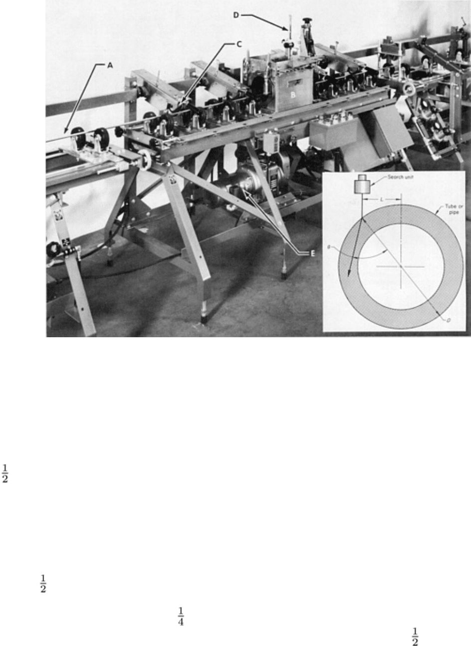
or immersion. The inspection unit contained a rotational and longitudinal drive mechanism and a relatively small open-
ended and glanded immersion tank through which the tube or pipe passes (Fig. 6). The tank also contained the search
units.
Fig. 6 Unit used for the ultrasonic inspection
of seamless and welded stainless austenitic steel tubular products.
A, tube being inspected; B, immersion tank; C, drive wheels; D, search-
unit tube; E, drive mechanism. Inset
shows lateral displacement of the search unit for circumferential inspection to detect longitudinal flaws.
To inspect, a reference tube or pipe was usually first placed in the unit. The reference tube or pipe was of a convenient
length (usually 1.2 to 1.8 m, or 4 to 6 ft) and similar in type, size, and wall thickness to the product to be inspected. The
reference tube contained notches in both outside and inside walls. Generally, the depth of the notches varied from 3 to
12 % of the wall thickness, with the shallower notch being used for seamless tube and the deeper notch for welded tube.
Most notches ran in the longitudinal direction and were approximately 25 mm (1 in.) long. Typically, the width of a notch
was not more than twice its depth. In some cases, transverse notches were used as well as longitudinal notches. The
dimensions of the transverse notch were the same as those of the longitudinal notch. The depth of notches was never less
than 0.10 mm (0.004 in.).
With the reference standard placed in the inspection unit, suitable search units were selected. For the detection of
longitudinal flaws, a line-focused search unit was generally used. The focal length varied from approximately 25 to 114
mm (1 to 4 in.). The short focal length was used for small-diameter tubing, and the longer focal tubing length was used
for larger-diameter tubing. The length of the beam (lined up with respect to the longitudinal axis of the tube or pipe)
varied from approximately 6.4 to 25 mm ( to 1 in.). The length of the beam used depended on the size of the flaw to be
detected. Shorter beam lengths were used to detect smaller (shorter) flaws. A beam 13 mm ( in.) long was normally
used. To detect transverse flaws, a spherically focused search unit could be used in addition to a line-focused unit.

The search unit was centered with respect to the reference tube, ensuring that a water gap between the search unit and the
tube was equal to the focal length of the search unit minus the radius of the tube. Angular adjustment and positioning
were performed to obtain a maximum response from the tube wall indicative of proper centering. For circumferential
inspection to detect longitudinal flaws, the search unit was displaced laterally or set off from the center of the tube to
obtain the proper angle at which the sound would travel through the tube wall (inset, Fig. 6). Generally, inspection was
performed using a shear wave traveling at an angle of 45° around the tube. The offset distance required was calculated
using the formula:
L = (D/2)(v
w
v
m
) sin θ
(Eq 1)
where L is the offset distance, D is the diameter of the tube or pipe, v
w
is the velocity of sound in water, v
m
is the velocity
of sound in the tube, and is the desired refracted angle in the tube or pipe. The value for the velocity of sound in the tube
depended on whether a longitudinal or shear wave was to be used. The offset value obtained from Eq 1 was an
approximation. The actual amount of offset was adjusted from that calculated to obtain best presentation and equalization
of responses from outside and inside notches.
When the search unit and reference tube or pipe had been properly located with respect to each other, the reference tube
was rotated and driven longitudinally past the search unit. Controls of the ultrasonic instrument were adjusted to display a
clear response from both inside and outside notches on an oscilloscope screen. The controls of the flaw-alarm module of
the instrument were adjusted to position the gate properly to include the signals from the notches and to activate the alarm
when they were detected. The pulse-repetition rate of the instrument was adjusted high enough to ensure the detection of
all notable flaws at the speed of inspection.
The inspection speed was controlled by the rate of rotation and longitudinal movement per revolution (pitch) of the tube.
The allowable pitch was a function of the length of the line-focused ultrasonic beam and the size of the flaw to be
detected. Normally, when the reference standard was passed through the unit, the controls had been adjusted to provide
more than one signal from each of the notches. When this had been established, the system was properly calibrated for
production inspection.
Ultrasonic Inspection Precautions. Generally, a chart recorder is employed to provide a permanent record of the
inspection described in Example 2. Multiple search units can be used in the immersion tank to provide several
simultaneous inspections during one pass of the pipe or tube through the unit. Specifications may call for circumferential
inspection from two directions because the reflection from a flaw may vary, depending on the direction in which the
ultrasonic beam strikes it. In addition to the circumferential inspection to detect longitudinal flaws, a longitudinal (axial)
inspection may be required to detect transverse flaws. Also, it may be desirable to ultrasonically measure wall thickness,
eccentricity, or both. All these tests can be performed at the same time by utilizing search units that are designed for the
tests and that are properly positioned in the tank.
Normally, rejection is based on the presence of flaw indications exceeding those from the reference notch. Reworking and
reinspection are generally permitted if other requirements, such as minimum wall thickness, are satisfied.
Other refinements are included in, or can be added to, the inspection system. For example, the feeding of tubes to the unit
and their withdrawal can be automated. Various audible and visible alarm systems and marking devices can be added.
Normally, the water used in the system is filtered and deaerated. Air entrapped in the water can produce false indications.
Similarly, water on the inside surfaces of tubes will produce false signals, and these surfaces must be kept dry. Tubes are
connected to each other by stoppers or by taping the ends together. The glands at each end of the water tank must be cut
in a manner that will allow passage of the tubes without undue loss of water couplant. Finally, air must be prevented from
being drawn into the entry gland along with the tube. This is usually accomplished by directing a stream of water over the
outside of the tube just before it enters the gland.
In eddy current inspection, use of an encircling detector coil is limited to a maximum tube diameter of about 75 mm
(3 in.). As tube diameter increases, the ratio of flaw size to tube diameter decreases; consequently, the flaw is increasingly
more difficult to detect. This problem is overcome by using several small probe coils (Ref 6, 7, and 17) and with spinning
probes (Ref 8). When probe coils are used, the flaw becomes a significantly high percentage of the zone surveyed.
Because independently mounted probes ride over the tube surface, good magnetic coupling is ensured. Magnetic
saturation is used to obtain maximum sensitivity to flaws close to, or on, the inside surface of the tube, and the frequency
of the test current is kept relatively low, sometimes as low as 1 kHz. Internal spinning probes can also be used if a lower
production rate can be tolerated (Ref 8).
In some installations, the eddy current test with magnetic saturation is supplemented by a probe-type eddy current test,
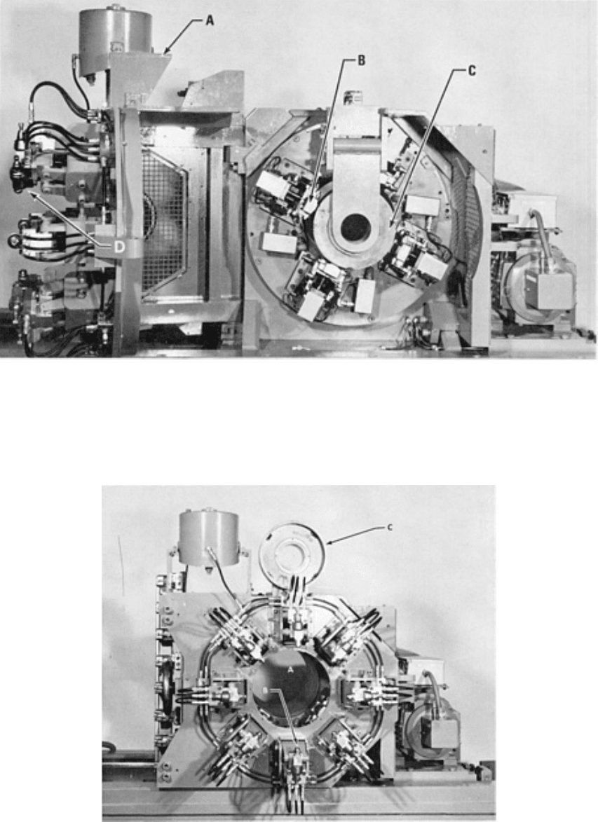
which in effect provides high-sensitivity inspection of the surface (Ref 18). Four probe coils, as shown in Fig. 7, each
serving as both inductor and detector, rotate about the tube as it moves longitudinally through the rotating assembly.
Magnetic saturation is not required. The segment of the tube in which the flaw occurs is identified by markers. In Fig. 8,
the test head is shown ready for use, with eight paint-spray guns in position for marking the proper zone.
Fig. 7 Unit used for the probe-type eddy current inspection of seamless steel tubing
. A, outer cover, containing
test head (Fig. 8), in open position; B, one of four rotating eddy current probe coils; C, reference-
standard
testpiece in position for calibration; D, one of eight paint-spray guns for marking
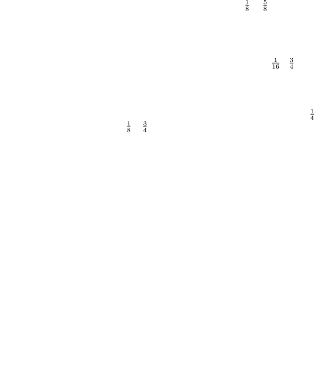
Fig. 8 Test head of the eddy current inspection unit shown in Fig. 7
. A, orifice for test pipe or tube; B, one of
eight paint-spray guns for marking; C, reference-standard testpiece
Eddy current inspection is used on seamless tubular products ranging from 3.2 to 244 mm ( to 9 in.) in diameter and
from 0.25 to 14.0 mm (0.01 to 0.55 in.) in wall thickness. In most cases, magnetic saturation is used, but when the
primary concern is the detection of surface imperfections, small probe coils without magnetic saturation are used. If the
steel is entirely nonmagnetic, no saturation is required in any system. The frequency used ranges from 1 to 400 kHz and
depends on such variables as the wall thickness of the pipe or tube, the coil design and arrangement, and the use of
saturation. The spacing between the pipe or tube and the test coil(s) varies widely. However, for high sensitivity and
accuracy, it should be kept to a minimum and is occasionally kept to as little as 0.25 mm (0.01 in.). This clearance is
insufficient for practical use, and the usual clearance for production testing ranges from 1.6 to 19 mm ( to in.).
Although all flaws that usually occur in seamless pipe or tube can be detected by eddy current methods, external flaws are
more easily detected than internal flaws. Laminations are the most difficult flaws to detect. Some installations are
intended to detect surface flaws only.
Flux leakage techniques are used for the inspection of seamless tubular products ranging from 32 to 914 mm (1 to
36 in.) in diameter and from 3.2 to 19 mm ( to in.) in wall thickness. Because the flaws sought usually have a
significant longitudinal dimension, transverse magnetic fields are usually used. Longitudinal fields can be used but are
rarely considered necessary. As a rule, the transverse magnetic field is produced by a current passing through a conductor
located in the center of the pipe or tube. In some cases, the field is produced between the poles of an electromagnet or a
permanent magnet whose pole pieces are shaped to fit the pipe or tube diameters. The signal-generating movement of
either the tube or the probe with respect to the other is accomplished by rotating either tube or probe.
Sensitivity to inside surface flaws is a problem when using these methods; the problem becomes more serious as the wall
thickness increases. In some cases, the solution to the problem is a rotating internal probe moving through the tube or kept
stationary while the tube moves (Ref 8). Other installations depend on electronic filters and the difference in frequency
between the signals for internal and surface flaws (Ref 10).
The production rate of flux leakage inspection depends on many factors. The maximum permissible speed of probe or
tube movement with respect to the other is about 90 m/min (300 sfm). The circuits will respond almost instantaneously
when inspection speeds are kept below this speed limit. The principal limiting factor in production-output speed then
becomes the maximum tolerable length of the flaw, which in turn governs the pitch of the helix inspected. However, the
production rate can be increased to any desired level by the simultaneous inspection of several segments of the same pipe
or tube. Actual inspection speeds range from 0.9 to 60 m/min (3 to 200 sfm), depending on the diameter, the system used,
sensitivity required, and other variables. The methods that use external magnets can inspect at a much higher overall rate
than those that depend on an internal conductor for magnetization.
Magnetic particle and liquid penetrant inspection methods are simple and economical and are most useful for
surface inspection in specialized, small-scale applications. When applied to welded tubing, their use can be restricted to
the weld zone. However, when applied to seamless tubing, there are no surface restrictions. The inability of these methods
to locate small flaws beneath the surface and their dependence on the vision, alertness, and judgment of the inspector limit
their usefulness in meeting modern specifications for seamless steel tubing.
Radiographic Inspection. The principal application of radiography to seamless tubing, as with welded tubing, is the
inspection of girth welds joining the ends of tubes. Even in this application, it is apparent that it should be supplemented
by magnetic particle inspection (Ref 12).
References cited in this section
1. "Nondestructive Testing Terminology," Bulletin 5T1, American Petroleum Institute, 1974
6. H. Luz, Die Segmentspule--ein neuer Geber für die Wirbelstromprüfung von Rohren, BänderBlecheRohre,

Vol 12 (No. 1), Jan 1971
7. W. Stumm, Tube-Testing by Electromagnetic NDT (Non-Destructive Testing) Methods: I, Non-
Destr.
Test., Vol 7 (No. 5), Oct 1974, p 251-258
8.
F. Förster, The Nondestructive Inspection of Tubings for Discontinuities and Wall Thickness Using
Electromagnetic Test Methods: I, Mater. Eval., Vol 28 (No. 4), April 1970, p 21A-25A, 28A-31A
10.
P.J. Bebick, "Locating Internal and In
side Diameter Defects in Heavy Wall Ferromagnetic Tubing by the
Leakage Flux Inspection Method," Paper presented at the ASNT Convention, Cleveland, American Society
for Nondestructive Testing, Oct 1974
12.
R.F. Lumb and G.D. Fearnebaugh, Toward Better Sta
ndards for Field Welding of Gas Pipelines, Weld. J.,
Vol 54 (No. 2), Feb 1975, p 63-s to 71-s
17.
F.J. Barchfeld, R.S. Spinetti, and J.F. Winston, "Automatic In-
Line Inspection of Seamless Pipe," Paper
presented at the ASNT Convention, Detroit, American Society for Nondestructive Testing, Oct 1974
18.
T.W. Judd, Orbitest for Round Tubes, Mater. Eval., Vol 28 (No. 1), Jan 1970, p 8-12
Nondestructive Inspection of Tubular Products
Finned Tubing
The production of finned tubing for use in heat exchangers, notably, the heat exchangers used in nuclear reactor
installations, has been increasing. These tubes are normally designed with three or six fins, and the presence of these fins
precludes the use of several of the conventional inspection techniques. Among the methods considered to be feasible are
the magnetic particle, liquid penetrant, and eddy current methods. The tube wall just below the outer surface can be
inspected with a high degree of efficiency and speed using special eddy current techniques (Ref 19). For this application,
external coils are designed to fit the external tube contours precisely. The transmission method, in which the exiting and
receiving coils are placed on different sides of the tube wall, is used. Although ultrasonic inspection can be used, it is
prohibitively slow and expensive because of the finned-tube contours.
Reference cited in this section
19.
F. Förster, Sensitive Eddy-Current Testing of Tubes for Defects on the Inner and Outer Surfaces, Non-
Destr. Test., Vol 7 (No. 1), Feb 1974, p 25-35
Nondestructive Inspection of Tubular Products
Duplex Tubing
Exploratory tests have demonstrated the feasibility of applying several nondestructive inspection methods to the
inspection of duplex tubing used in the atomic energy industry. The tubes, which are made by metallurgically bonding
two concentric pieces of 2.25Cr-1Mo steel tubing to make a single piece, have a composite wall thickness of 3.86 mm
(0.152 in.) and an outside diameter of 22 mm ( in.). The outer 22 mm ( in.) diam tube is fabricated with four equally
spaced axial grooves on the inside surface. These grooves complicate testing, but laboratory experience indicates that a
useful inspection of the assembled tubes can be accomplished by the ultrasonic method (Ref 20). Complete inspection
requires scanning of the inside 14.5 mm ( in.) diam tube as well as the outer tube surfaces. Eddy current techniques
can also be used for inspecting duplex tubing, as will be shown in the next section, "Nonferrous Tubing," which includes
an example of the eddy current inspection of aluminum tubing (Example 3).
Reference cited in this section
20.
K.J. Reimann, T.H. Busse, R.B. Massow, and A. Sather, Inspection Feasibility of Duplex Tubes,
Mater.
Eval., Vol 33 (No. 4), April 1975, p 89-95
Nondestructive Inspection of Tubular Products
Nonferrous Tubing
*
A wide variety of nonferrous alloy tubing, such as tubing made of brass, copper, aluminum, nickel, and zirconium, can be
inspected for cracks, seams, splits, and other flaws. Eddy current inspection is the method most widely used, followed by
the ultrasonic and liquid penetrant methods.
Eddy Current Inspection
When eddy current inspection is employed for nonferrous tubing, the range of tube diameters normally permits the use of
an encircling coil. The typical flaws respond well to differential-type coils. The frequencies employed usually range from
1 to 25 kHz. The choice of frequency is generally dependent on the electrical conductivity and wall thickness of the
tubing. Because magnetic saturation is not required, the inspection equipment is simpler and more compact than that used
on ferromagnetic tubing. Tubes range from 3.2 to 89 mm ( to 3 in.) in diameter, with wall thicknesses from 0.25 to
14.2 mm (0.01 to 0.56 in.). Testing speeds to 370 m/min (1200 sfm) have been reported. On a limited basis, eddy current
inspection is also being applied to finned copper tubing.
Example 3: Corrosion of Duplex 3003-H14 Aluminum Heat Exchanger Tubes Clad With
7072 Aluminum on Inner Surface.
An eddy current inspection was performed at a petrochemical complex on a heat exchanger containing 1319 tubes. It was
advised that the tube material was aluminum alloy 3003 in the H14 condition. The tube side environment was salt water at
a pressure of 240 kPa (35 psig) at an inlet temperature of 30 °C (85 °F) and an outlet temperature of 40 °C (100 °F). The
shell side environment contained hydrocarbons, hydrogen sulfide, water, hydrogen, and ammonia. The shell side stream
entered at 125 °C (260 °F) and exited at 45 °C (110 °F) at 380 kPa (55 psig).
Eddy current inspection of the heat exchanger revealed that 300 out of 1319 tubes exhibited indications characteristic of
broad, inner-surface pitting corrosion. The suspect tubes were randomly scattered about the tube bundle.

A tube that exhibited strong indications of inner-surface pitting was pulled, split, and visually examined. The entire outer
surface of the tube was covered with a thin, uniform black scale. The inner surface of the tube was coated with light-
brown silt deposits. Broad, shallow corrosion pits were randomly scattered over the entire inner surface. Without
exception, at each of the corroded areas, the depth of the corrosion attack measured 0.28 mm (0.011 in.). Figure 9(a)
shows the outer and inner surfaces of the subject tube.
Fig. 9 Corrosion in duplex 3003-
H14 aluminum heat exchanger tubes clad with 7072 aluminum on inner
surface. (a) Macrograph showing aluminum tube samples removed from the s
ubject heat exchanger unit after
eddy current inspection. The outer surface of the tube is shown at the top. The center two sections illustrate the
condition of the inner surface before cleaning, and the bottom section shows the inner surface after removal
of
the light silt deposits. Broad patches of corrosion attack are evident on the inner surface. (b) Micrograph of the
inner surface of the duplex tube showing corrosion of the 7072 cladding (top section of photograph). The
corrosive attack was limited to
the clad thickness (0.28 mm, or 0.011 in.), and the substrate 3003 alloy was
not affected. 50×. Courtesy of J.P. Crosson, Lucius Pitkin, Inc.
Metallographic examination revealed the tube to be of duplex design; that is, it was clad on the inner surface. The
corrosive attack was limited to the cladding thickness of 0.28 mm (0.011 in.) as shown in Fig. 9(b). Qualitative
spectrographic analysis revealed the aluminum alloy 3003 tube material to be clad on the inner surface with aluminum
alloy 7072.
The examination revealed that the subject tubes had undergone galvanic corrosion. The 7072 cladding sacrificially
corroded as it electrochemically protected the substrate alloy; 7072 cladding alloy is sufficiently anodic in the tube side
environment to provide cathodic protection. Consequently, the corrosive attack penetrated only to the interface, then
proceeded laterally along the substrate surface, confined to the cladding. To the extent that the cladding remained over a
sufficient area, the substrate material was protected. Therefore, although the tubes exhibited corrosive attack, it was
apparent that considerable service life remained, and tube replacement was not recommended.
Example 4: Stress-Corrosion Cracking of Copper Absorber Tubes in an Air-Conditioning
Unit.
Eddy current inspection was performed on a leaking absorber bundle in an absorption air-conditioning unit. The
inspection revealed cracklike indications in approximately 50% of the tubes. The tube material was phosphorus-
deoxidized copper.
Two tubes with indications were pulled and examined visually and metallographically to determine the cause of cracking.
The outer surfaces of the tubes were irregularly stained with a green-blue-black film, apparently the result of reaction with
the shell side lithium bromide solution. The inner surfaces were covered with a thin, crusty green-black deposit that easily
flaked off from the surface. No significant corrosive attack was observed on the inner surfaces.
One of the pulled tubes exhibited a large, irregular longitudinal crack, as shown in Fig. 10(a). The other tube exhibited a
very fine longitudinal crack, as shown in Fig. 10(b).
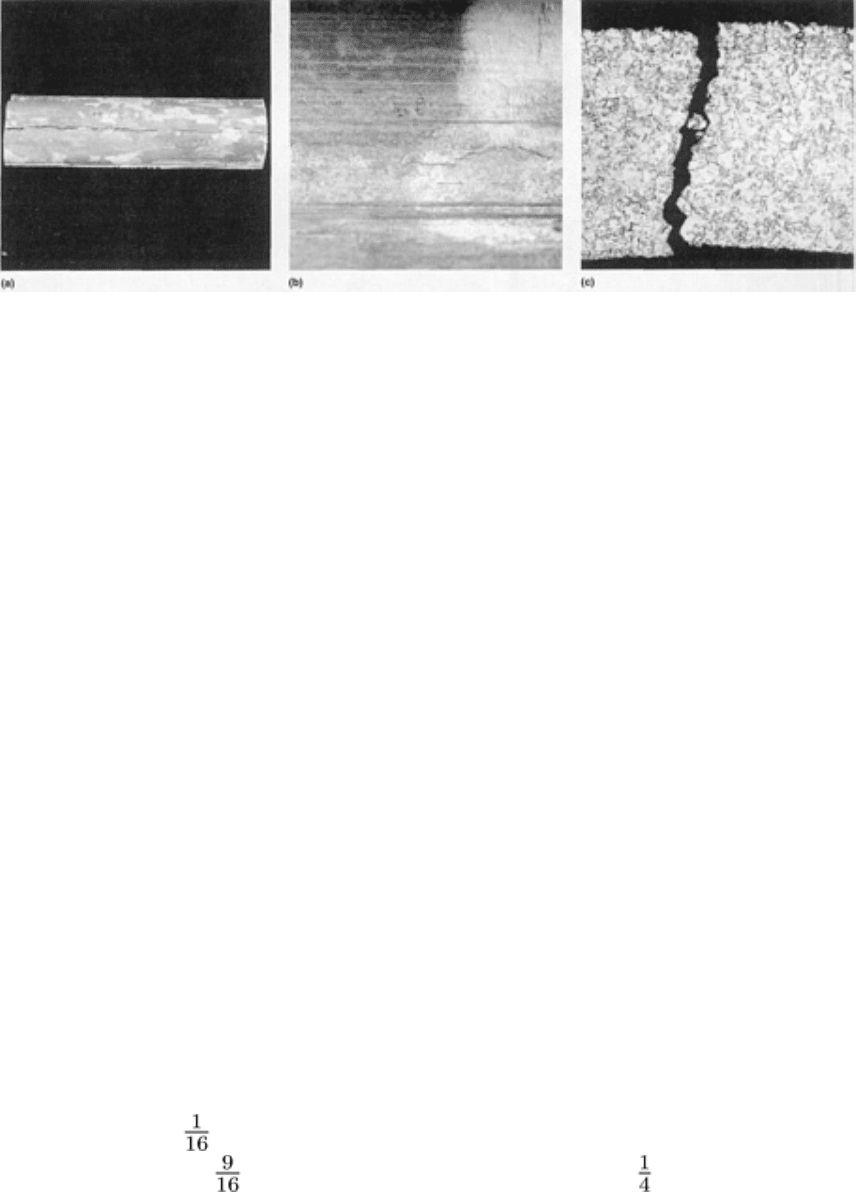
Fig. 10 Longitudinal crack and intergranular stress-corrosion cracks in copper air-conditioning absorber
tubes.
(a) Longitudinal crack in one of the subject absorber tubes. 0.75×. (b) Macrograph of fine, irregular crack
observed on the outer surface of the second absorber tube after light acid cleaning to remove the corrosion
product. 2×. (c) Micrograph show
ing profiles of the primary crack and two fine secondary cracks at the outer
surface of the subject absorber tube. The crack profiles are typical of stress-
corrosion cracking, that is,
intergranular and free of any localized grain deformation. 75×. Courtesy of J.P. Crosson, Lucius Pitkin, Inc.
Metallographic examination revealed that the cracks originated at the outer surface, were intergranular in nature, and were
free of any localized grain deformation. Such features are characteristic of stress-corrosion cracking in a copper heat
exchanger tube. The crack path is shown in Fig. 10(c).
The service contractor responsible for maintaining the absorption unit suspected that mercury contamination from a
manometer was the cause of the stress-corrosion cracking. However, an electron probe microanalysis performed on a
microspecimen did not reveal any mercury at or near the cracks.
Chemical analysis of the lithium bromide solution revealed significant quantities of nitrates in the solution. Such nitrates
are normally added to the lithium bromide solution to act as corrosion inhibitors.
The results of the examination indicated that the absorber tubes failed by stress-corrosion cracking initiated by ammonia
contamination in the lithium bromide solution. Cracking was from the shell side or outer surface of the tubes, where the
tubes were in contact with nitrate-inhibited lithium bromide. The source of ammonia was apparently the reduction of
nitrates by hydrogen evolved during corrosion of the steel shell and/or tubes.
Example 5: Burst Copper Evaporator Tubes in an Absorption Air-Conditioning Unit.
An eddy current survey of the copper evaporator (chiller) tubes in an absorption air-conditioning unit revealed two tubes
in the evaporator bundle with indications typical of longitudinal cracks. The two tubes were pulled for visual and
metallographic examination.
One tube exhibited a 27 mm (1 in.) long longitudinal crack adjacent to the location of the first tube support. The
second tube exhibited a 14.5 mm ( in.) long longitudinal crack 1735 mm (68 in.) from the front end. The tube
surface adjacent to the cracks appeared to be bulged and smeared. The smearing was apparently a result of removing the
tubes from the unit.
Splitting the tubes revealed the inner surfaces to exhibit a thin, normal, uniform oxide scale. The tube wall beneath the
scale was free of any significant corrosion.
Metallographic examination revealed significant necking down and grain distortion at the fracture surfaces, as shown in
Fig. 11. The fracture features were characteristic of an overload failure in a ductile material. The general microstructure
away from the fracture consisted of twinned equiaxed grains typical of annealed copper and was considered satisfactory.

Fig. 11 Micrograph of a transverse section of a burst copper evapora
tor tube showing the longitudinal rupture
present in one of the failed tubes. At the fracture, grain deformation and necking down of the tube wall are
evident. Such features are characteristic of overload failure in a ductile material. 55×. Courtesy of J.P
. Crosson,
Lucius Pitkin, Inc.
The results of the examination indicated that the ruptured tubes failed as a result of excessive internal pressure, as
evidenced by the necking down of the tube wall at the fracture. The normal operating pressure of approximately 690 kPa
(100 psi) produces a hoop stress in the tube wall of approximately 7.6 MPa (1100 psi), which was well below the yield
strength of the material. Therefore, the failure could not be related to minor fluctuations in operation pressure. The source
of the excessive internal pressure was most probably a freeze-up of the tube side water that occurred during interruption
of the tube side flow or misoperation of the unit.
Example 6: Worn Copper Condenser and Chiller Tubes in a Centrifugal Air-Conditioning
Unit.
Eddy current inspection was performed on the copper chiller and condenser tubes of a centrifugal air-conditioning unit.
The results of this inspection revealed the presence of seven chiller tubes exhibiting indications characteristic of a
decrease in wall thickness at a location corresponding to the forward tube support plate. Subsequent removal of these
tubes confirmed the presence of tube-wall wear at the saddle (smooth portion) of the tube, which sits in the tube support.
The tube-wall wear at the support saddles was measured between 10 and 60% of the original wall thickness.
Two condenser tubes were also observed with wear at the support saddles. The decrease in wall thickness was measured
to be 20% and 50% for the two tubes. Figure 12 shows several tubes with tube-wall wear at the tube support saddles.
Results of the inspection attributed the wear to fretting corrosion attack caused by vibrational contact between the tubes
and the steel tube support plate.
Fig. 12 Grooves at the tube
support saddles formed by fretting corrosion attack due to vibrational contact
between the copper tubes and the steel tube support plates. Courtesy of J.P. Crosson, Lucius Pitkin, Inc.
