ASM Metals HandBook Vol. 17 - Nondestructive Evaluation and Quality Control
Подождите немного. Документ загружается.

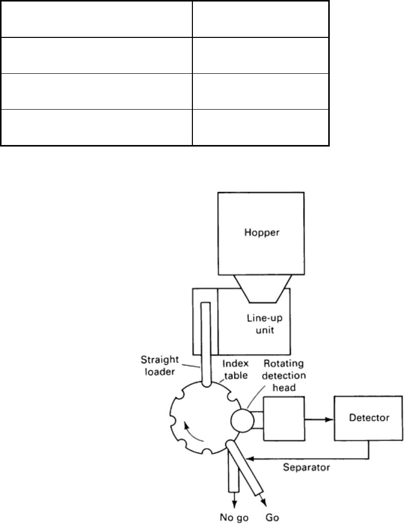
Testing speed, pieces/min
60
Number of rotations of detecting head, rev/min
300
Testing frequency, kHz
125
Probe type Self induction, self comparison
Source: Ref 1
Fig. 14 Schematic of eddy current flaw detection system used to inspect sheared bolt illustrated in Fig. 13
.
Source: Ref 1
After the bolt heads are detected with the rotating detection head, the bolts are classified as good/no-good and separated
according to detection result. Figure 15 shows the operation of the rotating detection head. The rotating detection head
repeats the following operations while rotating continuously regardless of the position of the bolt head to be tested:
• A bolt stops immediately under the detection head (Fig. 15a)
• The detection head descends while maintaining rotation (Fig. 15b)
•
The detection head approaches the bolt head, scans around the bolt head for two revolutions, and detects
the flaws (Fig. 15c)
• Pincerlike probe holders release from the bolt head, and the detection head ascends
• Bolt is conveyed to separator while next bolt is conveyed to the positio
n immediately under detection
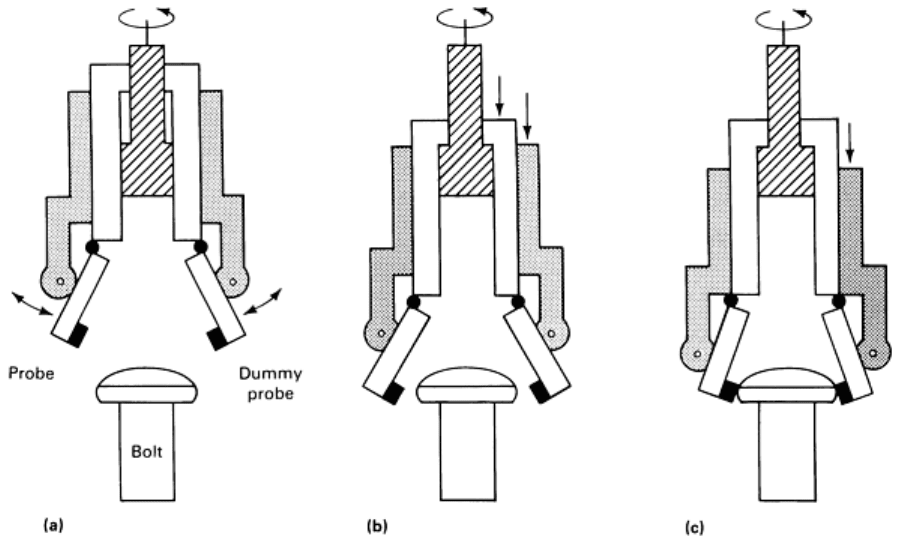
head
Fig. 15 Operation of rotating eddy current detection head. (a) Shear bolt positioned unde
r rotating detection
head. (b) Rotating detection head descends to lower probes into position to inspect bolt head. (c) Probe scans
bolt head as bolt undergoes two complete revolutions to detect flaws. Source: Ref 1
A detection rate of 60 pieces/min was maintained by the mechanism to keep the detection head rotating continuously.
Figure 16 shows the relation between flaw depth and signal output. Noise level is high at the circumferential surface of
the bolt head because of surface roughness, but the minimum detectable flaw depth is 0.3 mm (0.012 in.). Detailed
information on methods of electromagnetic inspection is available in the articles "Eddy Current Inspection" and "Remote-
Field Eddy Current Inspection" in this Volume.
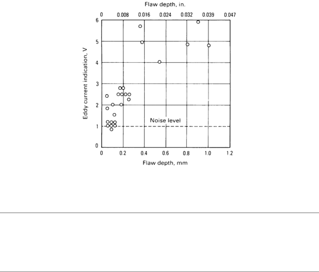
Fig. 16 Plot of eddy current signal output versus flaw depth to measure detectability of flaws in high-
tensile
sheared bolts. Source: Ref 1
Reference cited in this section
1.
N. Matsubara, H. Yamaguchi, T. Hiros
hima, T. Sakamoto, and S. Matsumoto, Nondestructive Testing of
Cold Drawn Wires and Cold Forged Products, Wire J. Int., March 1986
Nondestructive Inspection of Steel Bar, Wire, and Billets
Electromagnetic Systems
Electromagnetic systems include the systems that use magnetic fields generated by alternating current flowing in a
solenoid. A wide range of frequencies is used. As the alternating current flows through the solenoid, the magnetic field
generated induces eddy currents within the metal workpiece. These currents are affected by the electrical resistivity (more
commonly expressed as electrical conductivity--the reciprocal of resistivity), magnetic permeability, configuration,
homogeneity, surface irregularities, and flaws of the metal. The resistivity of the workpiece can vary because of the
chemical composition, crystal orientation, structure, and history of mechanical working. Permeability will vary over a
broad range, depending on the amount of stress present in the work metal. It increases slightly in the vicinity of a flaw
when the bar is subjected to a stress-producing operation.
Electromagnetic systems of flaw detection are broadly classified as:
• Those depending primarily on variations in electrical conductivity
• Those depending primarily on variations in magnetic permeability
Both systems are capable of detecting flaws in ferromagnetic bars. The conductivity-dependent systems can also be used
to detect flaws in nonferromagnetic bars.
Nondestructive Inspection of Steel Bar, Wire, and Billets
Eddy Current Systems
When electrical conductivity (resistivity) is the major variable relied upon, the test procedure is known as the eddy current
system. The alternating-field intensity is low, permitting the use of a correspondingly small inductor. Most eddy current
systems use a constant-voltage input derived from an electronic oscillator with a means of varying the output frequency
through a wide range, such as from 0.5 to 1000 kHz, in discrete steps.
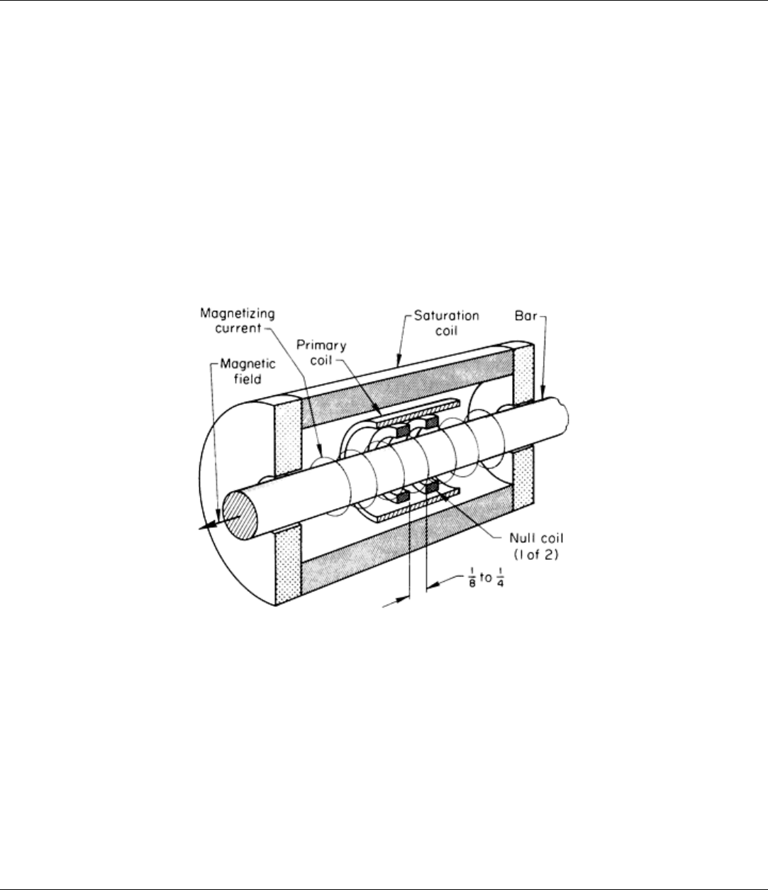
For general flaw detection, the range of 1 to 50 kHz is widely used. For ferromagnetic bars, a means must be provided to
eliminate or minimize the effects of permeability variation. This is usually accomplished by magnetically saturating the
bar being tested. The means for doing this is either a dc solenoid or a strong permanent magnet. A longitudinal section of
one type of eddy current coil assembly is shown in Fig. 17, a more detailed drawing of the rotating coil setup shown in
Table 4.
Fig. 17 Coil assembly for the inspection of steel bars by the eddy current system. Dimension given in inches
Eddy current inspection is especially useful for detecting and evaluating seams in steel bars. With this system, depending
on the circuitry used, a difference of as little as 0.025 mm (0.001 in.) in seam depth can be detected. Because of the skin
effect, the ability of eddy currents to penetrate into the test metal decreases in proportion to the increase of the frequency.
Eddy current inspection can be used without magnetic saturation for inspecting hot bars in the mill when the metal is
above the Curie temperature, because the metal is nonmagnetic at this temperature. Therefore, it follows that the magnetic
permeability system cannot be used to inspect hot bars.
Nondestructive Inspection of Steel Bar, Wire, and Billets
Magnetic Permeability Systems
Systems that depend on variations in magnetic permeability can be used for detecting flaws and for detecting differences
in composition, hardness, or structure. With appropriate instrumentation, both functions can be accomplished
simultaneously.
Flaw Detection. Magnetic permeability systems usually employ a solenoid (primary coil), which is excited by the
standard line frequency of 60 Hz with an adjustable current control to produce magnetic fields from 1000 to 30,000
ampere-turns; however, the solenoid is usually operated in the range of 10,000 to 15,000 ampere-turns. A typical coil
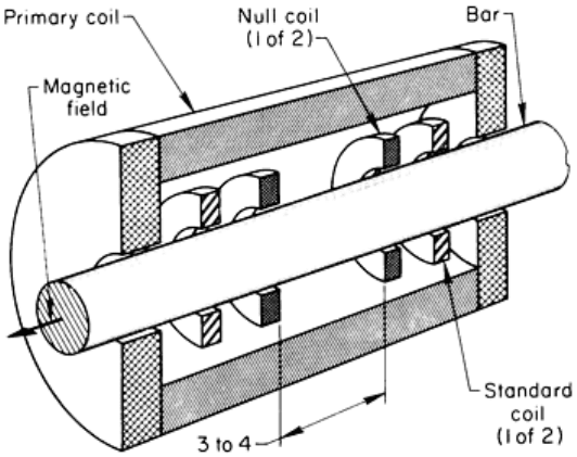
arrangement used for permeability systems is shown in Fig. 18.
Fig. 18
Coil assembly used for the simultaneous detection of flaws and of variation in composition, structure,
and hardness in steel bars. Dimension given in inches
As seen in Fig. 18, the coil arrangement consists of a primary coil (60 Hz), two null coils (zero-voltage-output coils), and
two standard coils. The secondary or pickup coils (null coils) are concentric with the primary coil, connected electrically
in opposition, and adjusted to a null or zero-voltage output. The null coils are usually spaced 75 to 102 mm (3 to 4 in.)
apart. The reason for this spacing is that a normal seam in a bar tapers into the bar to sound material. The variation in
stress level producing a measurable change in magnetic permeability is related to the change in seam depth found usually
within 75 mm (3 in.) of seam length.
Limitations for Flaw Detection. The detection of flaws by permeability systems depends on permeability variations
resulting from changes in stress, due to cold work or heat treatment, in the adjacent area of the flaw. These changes are
more or less directly proportional to the change in stress up to the elastic limit of the ferrous product.
These systems cannot be used to inspect hot-rolled or annealed bars unless they have been subjected to some uniform cold
work, such as rotary straightening for round material or planar-type straightening for square, hexagonal, or flat sections.
Gag-straightened bars are not suited to inspection by permeability systems, because of nonuniform high-stress
concentrations wherever the ram meets the work metal. Such stresses are far in excess of those for flaws in uniformly
stressed material.
The efficiency of flaw detection is a function of uniform residual stress levels within the bar. The five conditions that
follow are listed in order of decreasing efficiency for detection of flaws by permeability systems:
• Heat treated, quenched, drawn, and machine straightened
• Cold drawn and machine straightened
• Cold drawn, annealed, and machine straightened
• Hot rolled and machine straightened, centerless ground
• Hot rolled and machine straightened
After straightening, the bars should be aged 24 to 48 h at near room temperature for optimum sensitivity of flaw
detection. Aging can be hastened by stress relieving at low temperature in a furnace (up to 260 °C, or 500 °F).
The minimum seam depth that can be detected in cold-drawn, straightened round bars is approximately 0.025 mm (0.001
in.) for each 1.6 mm ( in.) of bar diameter; hexagonal and square bars with the same processing will be more sensitive.
For example, in a 25 mm (1 in.) diam round bar, a 0.41 mm (0.016 in.) seam is readily detected, while a 0.30 to 0.33 mm
(0.012 to 0.013 in.) seam can be detected in hexagonal or square bars. The reason for this difference lies in the residual
stress levels imparted by the rotary and planar straighteners.
Other flaws, such as laps, slivers, cracks, hard or soft spots, dimensional changes, cupping, chevrons, and pipe, are readily
indicated. For subsurface-type flaws, detection is possible only if they lie within the normal penetration range and are of
sufficient size to affect the inherent stress level. The penetration is approximately 6.4 mm ( in.) for low-carbon steels,
7.9 mm ( in.) for medium-carbon steels, and up to 13 mm ( in.) for many alloy steels.
One other factor not to be overlooked is the end effect, which prevents end-to-end inspection of the bar. As the front and
rear ends of the bar enter and leave the magnetic field, the field is grossly distorted, preventing inspection of the end
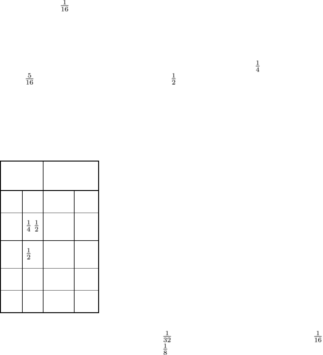
portions of the bar. For the average inspection speed of 37 to 46 m/min (120 to 150 sfm), the noninspected lengths will be
as follows:
Bar diameter
Noninspected length
at each end
mm in. mm
in.
6.4-13
-
102-152
4-6
13-25
-1
152-203
6-8
25-50 1-2 203-305
8-12
50-75 2-3 305-406 12-16
The signal obtained for a flaw of given size, as well as the amount of end effect, will vary somewhat with the amount of
draft used in drawing the bar. Using the normal 0.8 mm ( in.) draft as the basis for comparison, a 1.6 mm ( in.)
draft will increase the signal size by 50%, while a 3.2 mm ( in.) draft will produce an increase of about 90% (Fig. 19).
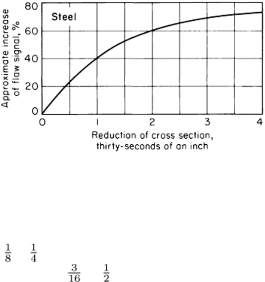
Fig. 19 Relationship between increas
e of flaw signal and increasing reduction of cross section (increasing draft)
for cold-drawn steel bars. Base reference is a hot-rolled bar.
All the above values hold true only when the secondary test coil is of the proper size; that is, the inside diameter of the
coil should be 3.2 to 6.4 mm ( to in.) greater than the bar diameter. The diameters of bar stock inspected by these
systems generally range from 4.8 to 140 mm ( to 5 in.).
Equipment for Detecting Flaws. The circuitry may include three types of electronic systems: the null system for the
detection of flaws (as explained above and shown in Fig. 18) and two identical standard systems, one of which is used for
detecting mixed grades in a given lot of steel and the other for indicating variations of hardness or structure. All systems
are independent and provide simultaneous indications with a single pass of the bar through the coil.
The null system utilizes a pair of matched windings that provides for the comparison of a section of the bar with another
section spaced some distance from the first. The matched windings are connected in opposition, and the resultant voltage
is therefore theoretically zero, making the wave displayed on the oscilloscope a straight line. In practice, however, such a
balance is seldom obtained. A small voltage with the wave-shape showing two peaks phase displaced 180° can normally
be seen on the oscilloscope screen (bar out, Fig. 20). When a bar is placed within the coils, the wave pattern changes (bar
in, Fig. 20). Should a flaw of minimum depth be present, the change in the waveshape is too small for measurement, even
though there is a differential voltage between the null coils. Therefore, other relationships must be used to provide the
desired information.
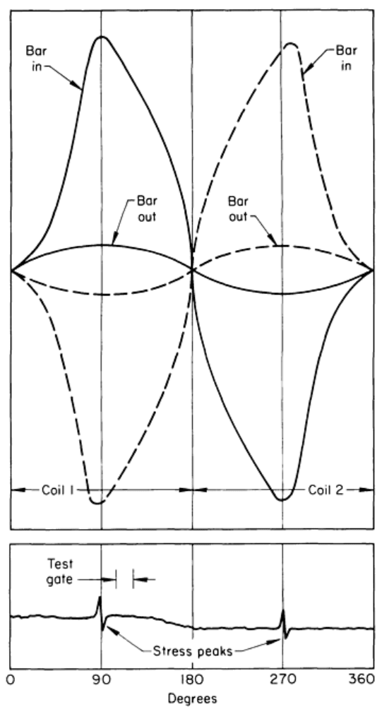
Fig. 20 Waveshape for oscilloscope pattern of a full
electrical cycle for empty coils (bar out) and loaded coils
(bar in). The position of an electronic gate for viewing an established portion of the cycle is shown.
The use of an electronic gate of any desired width permits these measurements to be made in any section of the wave. For
example, the test gate shown in Fig. 20 is adjustable to any position of the 360° cycle. It is normally positioned 8 to 20°
on either side of the stress peaks, where experience has revealed the wild stress effects are minimal and waveform
changes for flaws are readily detectable. Most systems provide a second electronic gate that can monitor the section of
waveshape where flaws cause a change in the saturation level, if this can be reached for the size and grade of material
under test. Deflections greater than a predetermined amount will energize a signal that indicates rejection.
Use for Sorting. The two standard systems differ from the null in that only one coil winding for each is utilized on the
bar being tested (Fig. 18). The voltage derived from this coil is balanced by a voltage in the instrument that is fully
adjustable to the degree that the zero-center meters can be adjusted to their midpoint while the oscilloscope presentation
continually shows the distorted waveshape. Should any undesired bars appear within the lot being tested, the meter
deflection will then provide power for activation of suitable alarm devices. The selectivity of the section of waveshape to

be monitored is provided by an electronic gate, adjustable through 180°. Only half of the full 360° wave is required, the
remainder being the negative duplicate of the positive and not shown on the oscilloscope. Both systems (standard coils,
Fig. 18) are fully independent and should be operated at different positions of the waveform to obtain as much
information as possible during the test. The standard system is used to monitor each bar in a lot for composition, hardness,
structure, and size and to indicate the presence of uniform-depth seams, cracks, and laps, which generally escape
detection by the null system.
Nondestructive Inspection of Steel Bar, Wire, and Billets
Equipment Requirements
In addition to coil arrangements such as those illustrated in Fig. 17 and 18, a fairly elaborate set of electronic gear is
required for inspecting steel bars. Some type of equipment for handling the bars and conveying them through the coils at
the desired rate is also required. The degree of sophistication designed into the equipment depends mainly on the number
of similar bars to be inspected.
Typical control units are adaptable to either the eddy current or the magnetic permeability systems of inspection. Many
variations are commercially available.
Nondestructive Inspection of Steel Bar, Wire, and Billets
Flaw Detection Procedure Using a Permeability System
The following description is presented purely as an example of setting up a procedure for detecting flaws by permeability
change using the null coils with one specific type of instrumentation. Procedures vary widely for various types of
equipment.
Select the proper size of secondary coil for the bars to be tested, and insert it into the primary-coil unit, making sure all
electrical connections are secure. Turn on the primary power, and adjust the coil current to about 8 A as shown on the
electrical meter on the power-supply panel. Adjust the combined coil unit so that the material will be concentric with the
inside diameter of the secondary coil. Select the appropriate feed-through speed of the conveyor system, and insert a bar
into the test coil. Turn the sensitivity on the null-equipment panel clockwise to about midposition, and while the bar is
moving in the forward direction, alternately adjust the balance x and y controls to bring the null waveshape, as seen on the
oscilloscope, to as near a straight line as possible. Do not stop the bar while making these adjustments, because it heats
rapidly and its permeability changes with increasing temperature, resulting in a flaw indication when passed through the
test coil on a repeat run. Furthermore, do not adjust the controls when the feed is reversed through the test coil, because
the magnetic field is dragged by the bar in the direction of travel and the balance obtained would not be correct for the
normal feed direction.
Assuming the oscilloscope controls are adjusted properly, the two stress peaks of the null waveshape will be located
equidistant from the edge of the tube face and 180° apart. Locate the index or gate about 10 to 15° to the right of the left
stress peak by use of its control knob, and adjust its height by the gain control so that it is easily recognizable. The choice
of using a 60-Hz filter, either in or out, is based on past experience when testing the same type of material with a similar
setup. Finally, readjust the sensitivity control so that the small fluctuations within the gate do not reach the preset trip
level for the various signaling devices.
Nondestructive Inspection of Steel Bar, Wire, and Billets
Sorting Procedure Using a Permeability System
The following example of a procedure for sorting involves the use of the standard coils (Fig. 18) for detecting variations
in hardness, grade, and structure, employing three different electronic gates within 180° (one-half cycle). In this case, the
same package of electronic gear is used for pickup from both the null and the standard coils.
Position the waveshape switch to the respective A or B standard circuit, and its oscilloscope trace will appear on the face
of the tube in place of the former null trace. Adjust the sensitivity control to the third or fourth step, and with a bar
feeding through the test coil, position the gate to its desired location by means of the coarse-gate and fine-gate set
controls. The associated zero-center meter will deflect either to the positive or negative side, and by turning the
compensator knob in the appropriate direction to deflect it toward its midpoint, the meter can be balanced to zero. A
rough adjustment can be made with the bar stationary in the test coil. When the bar is heated, the oscilloscope pattern
continually changes. By moving the bar forward two or three times while making the above adjustments, the final balance
can be obtained. The same procedure is used for the other circuit, but the gate should not be at the same position on the
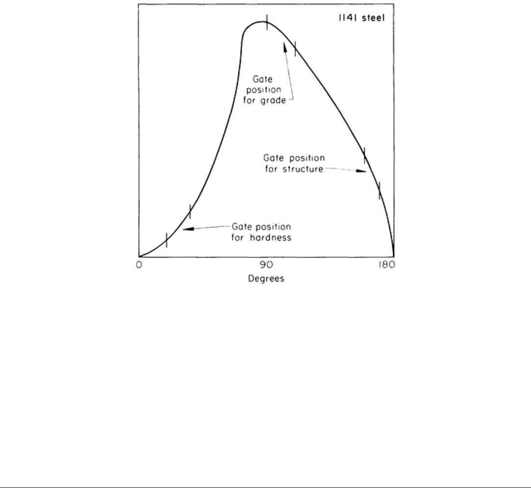
electrical cycle (Fig. 21). Figure 21 shows the waveshape for one-half of an electrical cycle for a bar of 1141 steel. The
three gate positions for detecting variations in hardness, grade, and structure are indicated on the waveshape.
Fig. 21 Waveshape for one-half of an electrical cycle as seen
on the screen of an oscilloscope with a bar of
1141 steel in the coil. Three electronic gate positions are indicated for inspecting for hardness, grade, and
structure.
The bar that was used for setup purposes should be set aside until testing of the whole lot of material is completed,
because every bar is being compared to the setup bar. Should the meters exhibit a deviation for the whole length of the
bar, the bar could be a different grade or contain a full-length seam or crack. A varying meter reading may indicate a
change of hardness or structure as well as a deep flaw. The latter will be simultaneously indicated by the null circuit. If an
unwanted grade of steel bars has been separated, it is advisable to retest this group, choosing one bar from the unwanted
lot for setup, because it is not unusual to find a third grade within a mixed lot of steel.
Nondestructive Inspection of Steel Bar, Wire, and Billets
Nondestructive Inspection of Steel Billets
