ASM Metals HandBook Vol. 17 - Nondestructive Evaluation and Quality Control
Подождите немного. Документ загружается.

Sintered P/M parts behave in a similar manner, and the minimum defect size that can be detected has been determined
experimentally by testing the resonant frequency after milling narrow grooves of various depths in the parts (Ref 24). It
was found that defects covering 2% of the cross section could always be detected and that smaller defects (down to 0.5%)
could be detected under favorable conditions of part geometry. This was later shown to apply to real defects as well as
machined grooves (Ref 25). There is no record of the technique having been tried on green parts. However, the extremely
high sound-damping capacity of green parts would appear to preclude its use. As with ultrasonic techniques, resonance
testing has been used to determine physical properties such as the elastic modulus of materials as well as their defect
structure (Ref 26).
Acoustic emissions are sounds generated in a material as stored elastic energy is released in a noncontinuous mode by
mechanisms such as transformation and twinning, slip, and fracture (see the article "Acoustic Emission Inspection" in this
Volume). The acoustic emission spectra have been characterized for the compressive deformation of powder-forged 4600
steels with carbon contents ranging from 0.3 to 0.9% (Ref 27).
If P/M tooling were monitored for acoustic emissions of the powder during compaction and ejection, it might be possible
to distinguish emission peaks due to the release of stored energy as cracks are formed. However, a developmental
program would be required to evaluate this concept and practical application is not anticipated.
Thermal Inspection
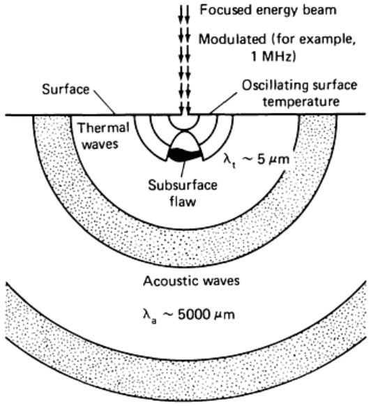
Thermal Wave Imaging. When a pulsed laser impinges on a surface, the rapidly alternating heating and cooling of
the surface is conducted into the body of the specimen, as shown in Fig. 18. These thermal waves have been shown to
possess many of the same characteristics as electromagnetic or mechanical waves. They can be reflected and refracted,
they can form interference patterns, and they interact with irregularities contained in the transmitting medium. In
coincidence with the thermal wave formation, acoustic waves are formed by the alternating expansion and contraction of
the area of impingement of the laser on the surface. These photoacoustic waves have the same frequency as the thermal
waves (typically 1 MHz) but have a much longer wavelength. They are also affected by scattering and reflection of the
thermal waves in the volume immediately surrounding the laser impingement point, and it is this effect that allows
detection of flaws. Thermal wave imaging has been used to detect delamination and microcracking in silicon integrated
circuits (Ref 28).
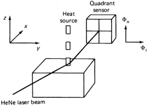
Fig. 18 Transmission of thermal and acoustic waves in thermal wave imaging. Source: Ref 28
Another method of detecting the interactions of thermal waves with defects is optical beam deflection, or the mirage
effect (Ref 29). The impingement point of the laser on the surface heats rapidly, and the air around this point is also
heated. If there are no irregularities present beneath the surface, this volume of lower-density heated air is roughly
hemispherical in shape. A second laser beam that transits this low-density air volume by skimming closely parallel to the
specimen surface, as shown in Fig. 19, will be refracted by the density gradient in the same way as it would be by a
conventional lens. A four-quadrant detector array gathers the beam deflection data as the specimen surface is scanned by
the laser. Subsurface defects are detected as changes in the shape of the density gradient "lens."
Fig. 19
Detection of interactions between thermal waves and flaws by optical beam deflection (mirage effect).
Source: Ref 29
Although there is no record of thermal wave imaging having been applied to P/M parts, the damping capacity of green
compacts would appear to restrict the potential application of the technique to sintered components only. Full details on
the principles and applications of thermal wave imaging can be found in the article "Thermal Inspection" in this Volume.
Electrical Resistivity Testing
Direct Current Resistivity Testing. A voltage field within a conductive solid will create currents that are influenced
by structural irregularities, including cracks and porosity. This characteristic has been used to measure carburized case
depth in wrought steels (Ref 30). The arrangement shown in Fig. 20 is used to measure the voltage drop in a current field
localized between two electrode probes. This method has been used to detect seeded defects in laboratory specimens. It
has also been successfully applied to the production of sintered steel parts (Ref 31), as described in Examples 1, 2, and 3.
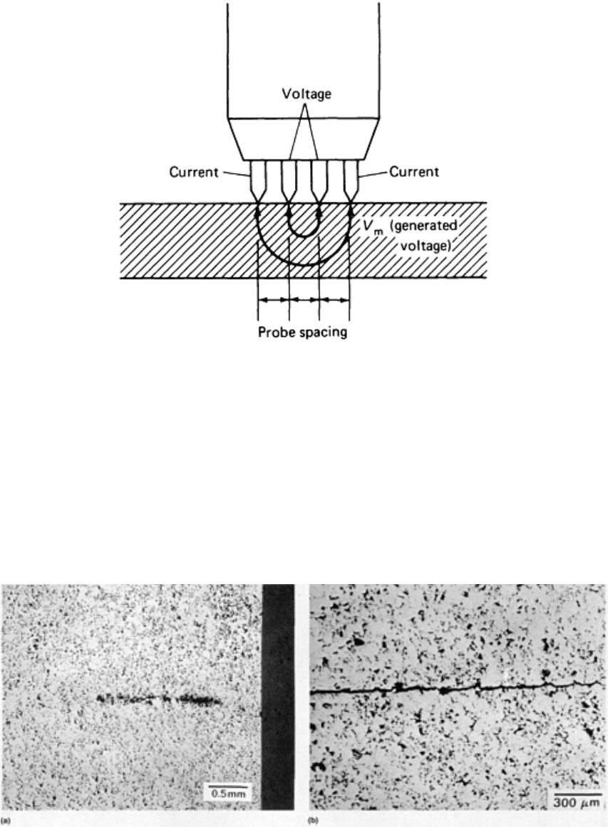
Fig. 20 Four-
point probe used in the resistivity test. The outer probe pins are the current leads; the inner pins
are the potential leads. Source: Ref 30
Although the resistivity of green compacts is an order of magnitude higher than that after sintering, the same technique
has been shown to apply (Ref 30). Green-state specimens with laboratory-simulated cracks of the type shown in Fig. 21
have been subjected to resistivity inspection with encouraging results. If the probe electrodes span the plane containing
the defects and if a series of measurements is made along the edge of the plane, the resistivity varies when defects are
present, as shown in Fig. 22. Other tests on green parts are described in Ref 30 and 31.
Fig. 21
Defects in green P/M compacts. (a) Artificial defect caused by the inclusion of a fine wax sliver in the
die fill. Unetched. (b) Artificial defect produced by compacting a partially filled die at 345 MPa (25 tsi),
completing the fill, and carrying out final compaction of the entire part at 620 MPa (45 tsi).
Unetched. See also
Fig. 22.
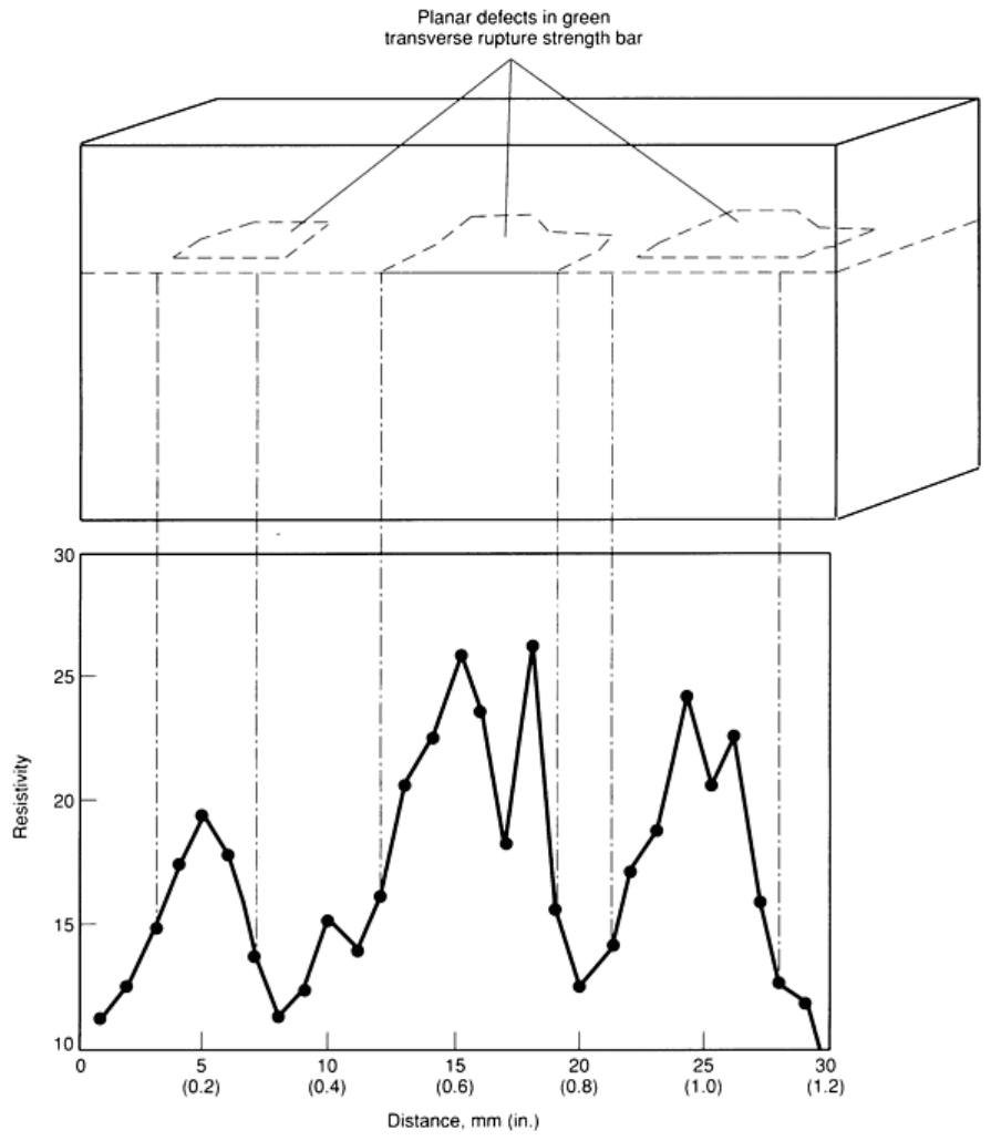
Fig. 22 Variation in resistivity in a green compact was used to locate artificial defects of the type shown in
Fig.
21(a) and 21(b). Source: Ref 30
There are two potential contributors to variability in the resistivity test. First, in addition to cracks, the edges and corners
of the parts distort the current fields. The internal corners of parts are often the sites of green cracks. Testing the volume
of material immediately underlying the corners necessitates the use of specially made electrode probe sets. Another
variable influencing the resistivity inspection of green compacts is the nature of the oxide layers on the particles. When
the oxide layer is altered with a thermal treatment, the resistivity of the green part decreases (Ref 32).
Another study has yielded the relative density/conductivity relationship shown in Fig. 23, suggesting that resistivity tests
could be used as a rapid check for localized density variations. As with ultrasound, the elastic modulus and the toughness
of porous steels can also be distinguished by resistivity checks (Ref 34).
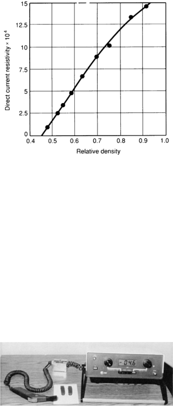
Fig. 23 Variation in resistivity with relative density in sintered iron. Source: Ref 33
The direct current resistivity test can be used on any conductive material; it is not limited to ferromagnetic materials.
Although further development is needed, resistivity measurements appear to be one of the most promising techniques for
the nondestructive evaluation of both green and sintered P/M parts. In addition to detecting cracks in green parts, as well
as part-to-part density variation, studies have shown that changes in resistivity due to poor carbon pickup during sintering
were also detectable (Ref 31). Resistivity testing has also been used later in the processing sequence to screen heat-treated
parts for incomplete transformation to martensite. Several uses for resistivity testing are given in the following examples
(Ref 31).
Example 1: Automotive Air Conditioner Compressor Part.
The resistivity-measuring equipment and hand-held probe are shown in Fig. 24. The part, shown in Fig. 25, was tested for
green cracking in the locations marked in Fig. 25(b), which were suspect because of prior experience. The parts could
then be sorted for cracks by comparing the measured resistivity with limiting resistivity values that had previously been
determined using parts with cracks indicated by magnetic particle testing. The prior test method consisted of sintering,
sectioning, and magnetic particle inspection, a 2-h process. This part was also the subject of a series of experiments
demonstrating that the resistivity test method had high reproducibility and was not operator sensitive.
Fig. 24 Resistivity-
measurement device for examining P/M parts. Courtesy of R.A. Ketterer and N.F. McQuiddy,
Ferraloy
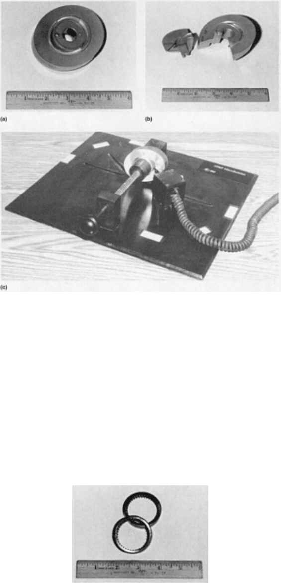
Fig. 25
Automotive air conditioner compressor part examined by resistivity measurement. (a) Actual part. (b)
Cross section showing flawed areas. (c) Six lo
cation test fixture. Courtesy of R.A. Ketterer and N.F. McQuiddy,
Ferraloy
Example 2: Automotive Transmission Spacer.
The resistivity test was used to screen the parts shown in Fig. 26 for incomplete transformation to martensite upon heat
treating. The test is based on the lower resistivity of pearlitic microstructures compared with martensitic microstructures
of the same chemistry. To determine a resistivity criterion for the screening of these parts, resistivity was correlated with
hardness measurements. A resistivity of 60 μΩ· cm was associated with a hardness of 30 HRC, and a go/no-go test
strategy was used. The prior test methods for this part were hardness measurements and metallography.
Fig. 26 Automatic transmission spacer examined by res
istivity measurement. Courtesy of R.A. Ketterer and
N.F. McQuiddy, Ferraloy
Example 3: Automatic Transmission Clutch Plate.
The part, shown in Fig. 27, was pressed, sintered, and sized. The resistivity test was then used to screen for part-to-part
density variations to levels below 6.8 g/cm
3
, which was shown to be a minimum density level for achieving the radial
crush strength specification for the part. Again, a limiting resistivity value was determined for the part; resistivity values
below 27.5 μΩ· cm were considered acceptable.
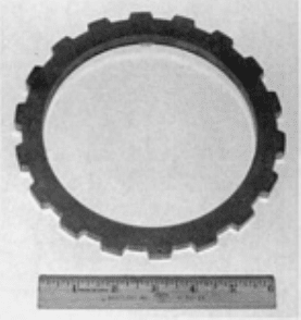
Fig. 27 Automatic transmission clutch plate examined by resistivity measurement. Courtesy of
R.A. Ketterer
and N.F. McQuiddy, Ferraloy
Eddy Current Testing. Another form of resistivity testing is the eddy current test. In this test, instead of producing
currents in the part by direct contact with electrodes, eddy currents are induced in the part by an alternating
electromagnetic field from an induction coil, as described in the article "Eddy Current Inspection" in this Volume.
Single-Coil Tests. Disruptions in the eddy current path due to any defect that changes the resistivity of the material are
detected as extraneous induced voltages in the induction coil. Alternatively, a separate detector coil can be placed in the
magnetic field around the testpiece.
The alternating current in the induction coil can vary from 1 to 1000 kHz. The depth of penetration varies with frequency,
with the highest frequencies yielding the smallest depths (skin effect). The way in which the eddy current varies as a
function of depth is also described in the article "Eddy Current Inspection" in this Volume.
The output of eddy current testing is in the form of an oscilloscope display. An eddy current inspection system can detect
changes from point to point in single testpieces (for example, welded tubes) as they move through the coil. For cases
where the testpieces consist of a series of discrete parts, a second coil containing a reference can be added to the system;
this configuration is called a magnetic bridge comparator.
Magnetic Bridge Comparator Testing. When a ferromagnetic part is placed in the core of a coil with an alternating
current, a unique set of harmonics characteristic to the part can be detected in the coil. Some of the variables influencing
the harmonics are alloy type, core or surface hardness, case depth, and porosity (Ref 35).
In the magnetic bridge comparator arrangement, the harmonic signals from two like coils are compared. The coils are
similar and carry the same excitation waveform. One coil contains the part to be inspected and the other a reference part
chosen at random from the group to be tested. Differences between the harmonic characteristics of the two parts are
displayed as the displacement of a dot from the center of an oscilloscope screen; no displacement means the two parts are
alike.
Although the magnetic susceptibility of porous sintered steels is reduced by the pinning of domain-boundary walls by
pores, P/M parts are also capable of being analyzed by the magnetic bridge comparator. In one study, 120 P/M production
parts were tested in a magnetic bridge comparator. Seventeen of the parts were singled out on the basis of a displacement
of the oscilloscope indication, as shown in Fig. 28. These parts were tested for chemistry, hardness, crush strength, and
pressed height. For comparison, 25 parts selected at random from the remaining specimens were also tested. Statistically
significant differences were found between the groups with regard to carbon content and hardness (Ref 36). The
technique has also been successfully applied to powder-forged parts (Ref 37). Although there are no published trials, there
is a possibility that the comparator could also be used for testing green compacts.
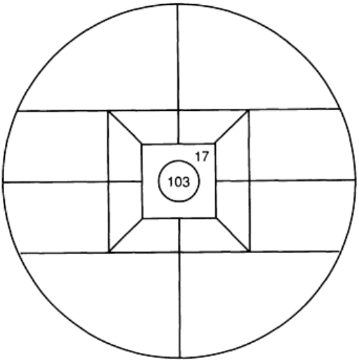
Fig. 28
Magnetic bridge comparator display for a set of 120 sintered parts, in which 17 parts were indicated as
differing from the reference part. Source: Ref 36
Visual Inspection and Pressure Testing
Magnetic Particle Inspection. Cracks that exist on or close to the surface of a ferromagnetic material in the magnetic
field act as magnetic poles, creating localized increases in the field intensity. Iron particles suspended in a fluid at the
surface will be preferentially attracted to these high-intensity areas, and these particles can be used to mark the locations
of the flaws. The detectability of the particles themselves can in turn be improved by coating with a pigment that contrasts
with the part surface or fluoresces under ultraviolet light (see the article "Magnetic Particle Inspection" in this Volume).
This method has been used to inspect finished P/M parts for cracks originating in processing, and it may also be
applicable to green compacts. It is also possible to automate the inspection process by using digital image processing (Ref
38).
Liquid Dye Penetrant Inspection. A liquid that wets the surface of the material being inspected will lower its
surface energy by residing preferentially in surface cracks and cavities. In the liquid penetrant inspection technique,
cracks are detected by removing the dye from the flat surface of the specimen. The dye that is left behind in the cracks is
then wicked out onto the surface by a fine particulate layer in which the pore radius is even lower than that of the crack.
The penetrant in this particulate developer layer can be detected visually because of its high contrast with the white
developer, or it can be mixed with a dye that fluoresces under ultraviolet light. This process is described in the article
"Liquid Penetrant Inspection" in this Volume.
The dye penetrant equipment found in P/M shops is generally used only for checking parts of the tooling and machinery
for cracks. The dye does not preferentially reside at cracks in P/M parts, because the pore radius and the crack radius are
equivalent. However, there might be an application for green parts because the surfaces of green parts are sealed against
penetration by liquids through smearing of the metal powder against the die wall and through the formation of a thin
coating of dry powder lubricant on the surface. Cracks intersecting the surface may form an opening in this layer that
could be detected by the dye penetrant.
Pore Pressure Rupture Testing of Green Compacts. A novel test is available for detecting ejection cracks in
green compacts (Ref 39). A pressure seal is formed around a corner or area of a part where experience has shown that
cracks are likely to occur. The area is then pressurized to about 3.5 MPa (500 psi) using a fixture such as that shown in
Fig. 29. If a crack is present, the gas pressure in the crack will be sufficient to propagate the crack the rest of the way
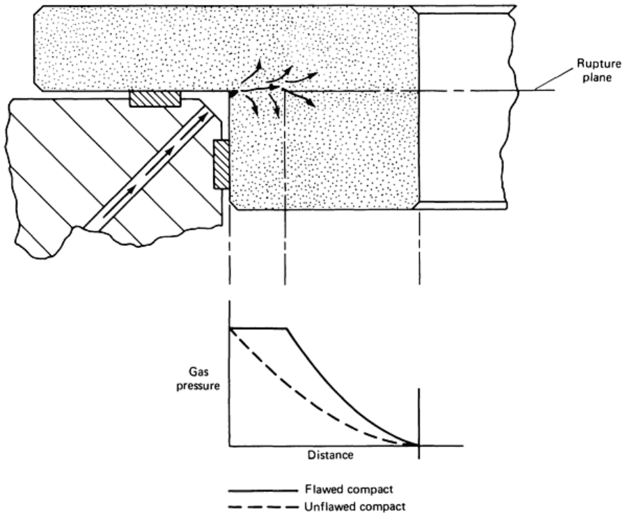
through the part. This would be classed as a proof test rather than a nondestructive test because the part is destroyed if
defects are present.
Fig. 29 Pore pressure rupture test for crack detection in green parts. Source: Ref 39
The test can be used in a nondestructive manner on sintered parts. The gas permeability of the pressurized area is
measured at reduced pressures, and the presence of cracks or low-density areas is indicated by high permeability, as
shown in Fig. 30.
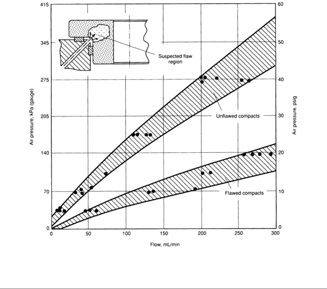
Fig. 30 Detection of flawed compact using the gas permeability technique. Source: Ref 39
References cited in this section
6. C. Rain, Uncovering Hidden Flaws, High Technol., Feb 1984
7. B. Chang et al., Spatial Resolution in Industrial Tomography, IEEE Trans. Nuclear Sci.,
NS30 (No. 2),
April 1983
8. H. Heidt et al., Nondestructive Density Evaluation of P/M Objects by Computer Tomography, in
Horizons
of Powder Metallurgy, 1986 International Powder Metallurgy Conference Proceedings, Part II, p 723
9.
G. Schlieper, W.J. Huppmann, and A. Kozuch, Nondestructive Determination of Sectional Densities by the
Gamma Densomat, Prog. Powder Metall., Vol 43, 1987, p 351
10.
C.T. Waldo, Practical Aspects of the Gamma Densomat, in Horizons in Powder Metallurgy,
1986
International Powder Metallurgy Conference Proceedings, Part II, p 739
11.
J.L. Rose, M.J. Koczak, and J.W. Raisch, Ultrasonic Determ
ination of Density Variations in Green and
Sintered Powder Metallurgy Components, Prog. Powder Metall., Vol 30, 1974, p 131
12.
B. Patterson, C. Bates, and W. Knopp, Nondestructive Evaluation of P/M Materials, Prog. Powder Metall.,
Vol 37, 1981, p 67
13.
M.F. Termine, "Ultrasonic Velocity Measurements on Green and Sintered P/M Compacts," Unpublished
Report, Hoeganaes Corporation, 1985
