ASM Metals HandBook Vol. 17 - Nondestructive Evaluation and Quality Control
Подождите немного. Документ загружается.

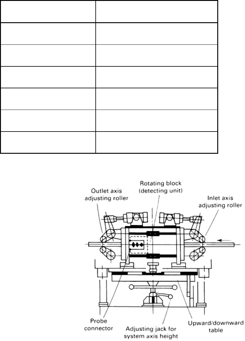
Table 1 Specifications of a rotating-type ultrasonic flaw detection system
Parameter
Specifications
Dimension of material, mm (in.)
15-32 (0.59-1.26)
Testing method
Normal-beam method and angle-beam method
Testing frequency, MHz
10 and 5
Number of rotations of probe, rev/min
1000
Signal transmit
Noncontact rotation transmit
Marker One each for near-surface flaw and inside flaw
Source: Ref 1
Fig. 5 Schematic of a typical rotating-type ultrasonic flaw detection system. Source: Ref 1
For flaws located immediately under the surface, the angle-beam method record can detect flaws as small as 0.2 to 0.3
mm (0.008 to 0.012 in.). Flaw echoes this small are not detectable with the normal-beam method.
Cold-Drawn Hexagonal Bars (Ref 1). Requirements for strict quality assurance are increasing for gaging inside flaws
to the same level as surface flaws. The conventional testing method is manual detection with the normal-beam method.
Because this method requires testing with plural directions, working efficiency is low. Furthermore, an untested zone
remains at the area immediately under the surface. Therefore, a testing system using the entire cross section with higher
efficiency has been sought.

Higher efficiency has been attained by incorporating an automated ultrasonic flaw detection system with probes for each
face of the material to detect separately the flaws located on the inside area and the near-surface area (Fig. 6). Flaws
inside the material are detected with the normal-beam method at each face of the material. In this method, the untested
zone remains in the near-surface area. Therefore, surface and near-surface area flaws are detected with the angle-beam
method at each face of the material. That is, six normal-beam probes and six angle-beam probes are located on the
circumference of the materials to be tested, which is conveyed longitudinally. The probe positions are arranged so that the
entire cross section can be detected. The probe holder is designed so that all the probes can be adjusted simultaneously by
adjusting one when the material size is changed. The coupling medium is a special oil that has low ultrasonic attenuation
and causes no rust on the material to be tested. Table 2 lists the specifications of the system.
Table 2 Specifications of an ultrasonic flaw detection system for cold-drawn hexagonal bars
Parameter
Specifications
Dimension of material, mm (in.)
12-32 (0.472-1.260)
Testing method
Normal-beam, 6 channels; angle-beam, 6 channels
Testing frequency, MHz
5
Probe position
Fixed in circumferential direction
Marker Two for near-surface flaw and inside flaw
Source: Ref 1
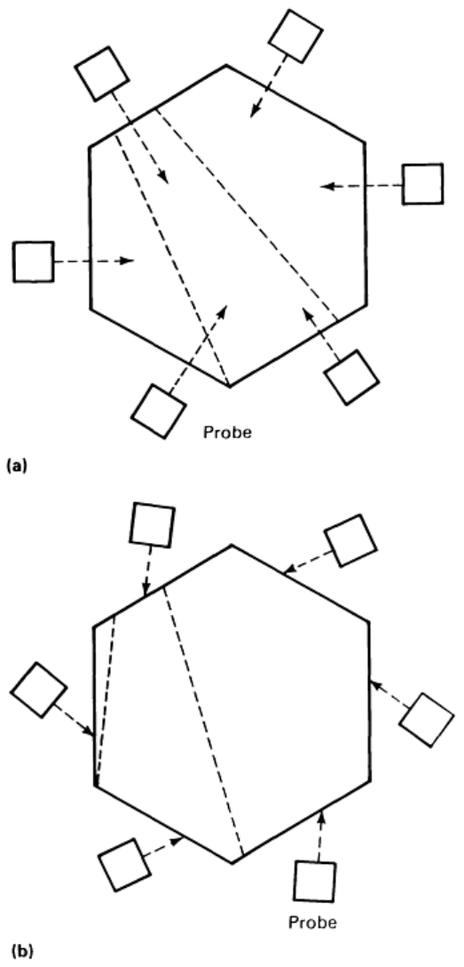
Fig. 6 Dual set of six circumferentially mounted probes used to ultrasonically detect flaws in cold-
drawn
hexagonal bars. (a) Normal-beam method to detect flaws deep inside bar. (b) Angle-
beam method to detect
surface and near-surface flaws. Source: Ref 1
Flaws larger than 0.3 mm (0.012 in.) can be detected at the near-surface area. Flaws measuring at least 0.2 mm (0.008 in.)
can be detected deep inside the hexagonal bar material.
Ultrasonic Flaw Detection on Cold-Drawn Wires (Ref 1). Surface flaw inspection is important for drawn wires. A
rotation-type eddy current flaw detection system is used for quality assurance. However, inside flaw inspection has been
urgently needed because on-line inspection has been considered impossible.
In quality assurance for drawn wires, rotating-type eddy current flaw detection has been used in combination with rotating
ultrasonic flaw detection to detect surface defects and inside flaws, respectively, in a two-step process. However, the high
cost and inefficiency of this method have prompted the development of a system with a rotating-type ultrasonic flaw
detection unit that can also detect surface flaws.
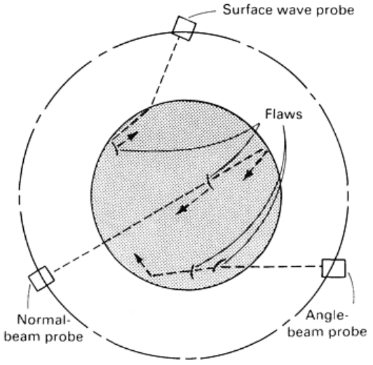
An additional die is placed behind the cold-drawing die to stabilize the vibration of the material. A detection unit, which
has probes arrayed in a circumferential direction, is placed between these dies. There are three detection modes (Fig. 7):
• Surface wave detection mode for surface defects
• Angle-beam detection mode for near-surface defects
• Normal-beam detection mode for inside defects
Fig. 7 Principle of ultrasonic flaw detection for cold-drawn wires using three detection mode probe. Source:
Ref
1
The ultrasonic incident angle can be optimized according to material dimensions. Water, the coupling medium, is always
kept in full quantity even in high-speed rotation. Thus, the system has the stable mechanism to provide constant detection.
One advantage of this system is that linear defects can be detected by surface wave detection at the same level as an eddy
current method. Another is that the entire cross section can be covered by means of a combination angle-beam/normal-
beam method. Table 3 summarizes the specifications of this setup.

Table 3 Specifications of an ultrasonic flaw detection system for cold-drawn wires
Parameter
Specifications
Dimension of material, mm (in.)
15-30 (0.590-1.181)
Testing frequency
Normal beam: 10 MHz, 1 channel
Angle beam: 5 MHz, 2 channels
Surface wave: 5 MHz, 2 channels
Number of rotations of probe, rev/min
1000
Signal transmit
Noncontact rotation transmit
Marker One each for near-surface flaw and inside flaw
Source: Ref 1
Results of experiments with this system showed detectability of 0.1 mm (0.004 in.) minimum flaw depth on surface
defects and 0.2 mm (0.008 in.) minimum inside defect size. This system enables the user to inspect the entire cross
section of cold-drawn wires to a high degree of accuracy. Detailed information on the fundamentals, equipment, and
techniques for ultrasonic inspection is available in the article "Ultrasonic Inspection" in this Volume.
Electromagnetic Inspection Methods
Electromagnetic methods of inspection are used far more extensively for nondestructive inspection of steel bars than any
of the methods discussed above. Electromagnetic methods are readily adaptable to automation and can be set up to detect
flaws, as well as a number of different compositional and structural variations, in bars on a mass-production basis.
Equipment can be relatively simple, but for mass-production inspection the equipment may be highly sophisticated and
costly. Such equipment can not only detect flaws and indicate them on an oscilloscope or other form of readout but can
also mark the location of the flaw on the bar before it emerges from the inspection equipment and can automatically sort
the bars on the basis of seam depth.
Eddy Current Testing of Cold-Drawn Bars (Ref 1). Surface defects on cold-drawn bars can be inspected by eddy
current detection methods using an encircling coil. This method utilizes a rotating probe that detects surface defects with
the probe coil rotating at high speed around the circumference of the cold-drawn bars.
The encircling coil method exhibits lower detectability on linear flaws because flaw detection depends on the difference
between two test coils in which the material to be tested is encircled. On the other hand, the method of rotating the probe
coil at high speed along the circumference of the material to be tested can detect linear defects because it detects bars in
spiral scanning.
Table 4 lists the specifications of the detection system. One of the main features is signal transmission in the probe
rotation unit by the noncontact rotating transmit method, which requires no maintenance work. Guide sleeves are placed
in front of and behind the probe to maintain a constant distance between the probe and the material to be tested, which is
important for acceptable performance of the system (Fig. 8). Furthermore, the rotation axis of the probe and the axis of
the material to be tested are kept in a line by pinch rollers placed in front of and behind the detector. On the probe, a
distance sensor is used for the automatic gain control function to provide electric compensation against distance variation.
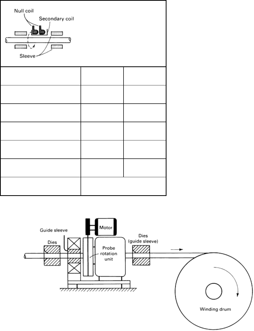
Table 4 Specifications of a rotating probe type eddy current flaw detection system
Parameter Type I
Type II
Dimension of material, mm (in.) 5-32 (0.197-1.260)
5-25 (0.197-0.984)
Number of probes 2
4
Probe area, mm
2
(in.
2
) 10 (0.016)
5 (0.0078)
Number of rotations of probe, rev/min
3000
6000
Testing frequency, kHz 64
512
Signal transmit Noncontact rotation transmit
Source: Ref 1
Fig. 8 Schematic of a rotating probe type eddy current flaw detector. Source: Ref 1
Figure 9 shows the relation between flaw depth and signal output. Natural flaws produce a larger deviation in signal
output than artificially introduced flaws because of the complicated cross-sectional configuration of the flaw, but the
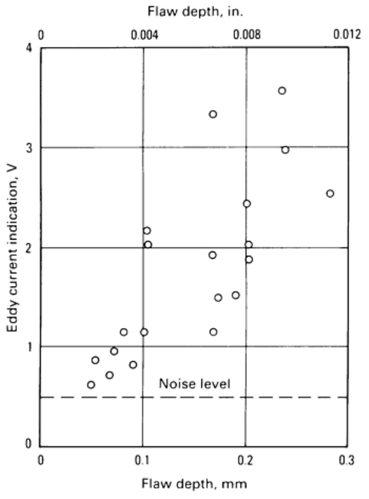
minimum detectable flaw depth is 0.1 mm (0.004 in.). Detectable flaw length depends on the feeding speed of the
material, the number of probes, and the number of rotations. For example, at a speed of 60 m/min (200 sfm), the full
surface is converted, and the minimum detectable flaw length is as long as the length of the probe coil.
Fig. 9 Plot of eddy current signal output versus flaw depth to gage detectability of flaws in cold-
drawn bars.
Source: Ref 1
Eddy Current Flaw Detection on Cold-Drawn Hexagonal Bars (Ref 1). Cold-finished steel profiles (hexagonal
bars) are mainly used as the raw material for couplers in oil pressure piping, an application for which quality assurance is
important. Surface defects on cold-drawn hexagonal bars include cracks derived from the cold-working process as well as
material flaws, both of which are long, longitudinal defects. It is impossible to detect these defects by the differential
method using encircling coils. The rotating probe method is also not applicable, because of the hexagonal form. An
automated flaw detection system for cracks initiated by the working process was developed using the eddy current flaw
detection system by a standard voltage comparison method.
There are two methods for testing cold-finished steel hexagonal bars: the standard voltage comparison method with
encircling probes (Fig. 10b) and the differential method with probe assembly (Fig. 10c). There is no effective difference
in detectability between these two methods. For the probe assembly method, it is necessary to consider the differences in
detectability of each individual probe, which is not necessary for the standard voltage comparison method.
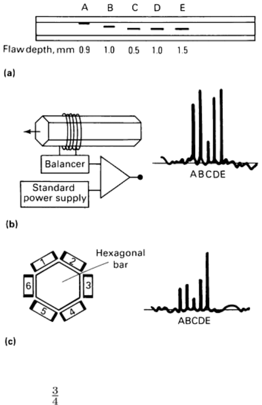
Fig. 10 Eddy current flaw detection method for cold-
drawn hexagonal bars. (a) Location of artificial flaws
ranging from 0.5 to 19 mm (0.020 to
in.) below probe position. (b) Schematic of setup for standard voltage
comparison (encircling coil) method (left) and plot of signals obtained for the designated flaw depths (right). (c)
Schematic of setup for differential
(six probe coil assembly) method (left) and plot of signals obtained for the
designated flaw depths (right). Source: Ref 1
The standard voltage comparison method is inferior in detectability to the rotating probe method, but is less expensive and
can efficiently detect cracks resulting from the cold-working process. This method, which can detect material flaws more
than 0.6 mm (0.024 in.) deep, is illustrated in Fig. 11.
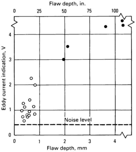
Fig. 11 Plot of eddy current signal output versus flaw depth to measure detectability of flaws--
specifically
material flaws (open circles) and process-induced cracks (closed circles)--in cold-
drawn hexagonal bars.
Source: Ref 1
Eddy Current Flaw Detection of Cold-Drawn Wires (Ref 1). Surface flaw detection on wire drawing line has
been conducted by the encircling-type eddy current method. However, this method has difficulty in detecting linear flaws.
A rotating probe type eddy current detection method can be effective, as illustrated in Fig. 8 for use on cold-drawn bars. It
is important in the rotating probe method to maintain a constant distance between the probe and the material to be tested.
The rotating unit, is positioned between dies where the smaller vibration of the material is expected. Guide sleeves are
used to adjust the rotating axis and the axis of the material to be tested.
Detectability is illustrated in Fig. 12. Flaws having a 0.1 mm (0.004 in.) minimum depth are detectable.
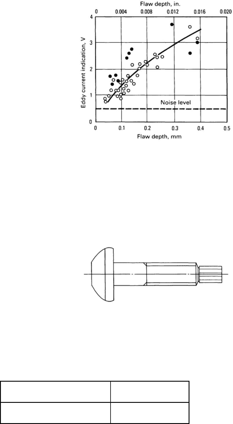
Fig. 12 Plot of eddy current signal outp
ut versus flaw depth to measure detectability of flaws, specifically
cracks (open circles) and scabs (closed circles), in cold-drawn wires. Source: Ref 1
Eddy Current Flaw Detection for a Cold-Forged, High-Tensile Sheared Bolt (Ref 1). Figure 13 shows a
general view of a high-tension sheared bolt. This type of bolt has a head with a round cross section and is mainly used for
general construction and bridge applications. This bolt is produced by cold forging from cold-drawn wires in the diameter
similar to the outside diameter of a threaded part of the bolt. The head is the most severely processed part of the bolt. The
circumferential part of the bolt head is formed between punch and die during cold forging. Therefore, cracks tend to occur
on the head. Eddy current testing can detect flaws in the bolt head at high speed with the probe rotating method.
Fig. 13 Schematic of a high-tension sheared bolt.
Figure 14 shows a general view of the inspection system used. Table 5 lists the main specifications. Bolts are conveyed
from hopper to line-up unit. Lined-up bolts are conveyed to the index table by straight feeder and then conveyed
intermittently to the rotating detection head and further to the separator.
Table 5 Specifications of an eddy current detection system for a high-tension sheared bolt
Parameter
Specification
Material
M20
