ASM Metals HandBook Vol. 17 - Nondestructive Evaluation and Quality Control
Подождите немного. Документ загружается.


Fig. 24 Offset or mismatch (high-low), which is a misalignment of the pieces to be welded. Ra
diographic
image: An abrupt change in film density across the width of the weld image. Welding process: SMAW. Source:
E.I. Du Pont de Nemours & Company, Inc.
Fig. 25 Burn-through, which is a severe depression or a crater-
type hole at the bottom of the weld but usually
not elongated. Radiographic image: A localized darker density with fuzzy edges in the center of the width of the
weld image. It may be wider than the width of the root pass image. Welding process: SMAW. Source: E.I. Du
Pont de Nemours & Company, Inc.
Undercuts result in a radiographic image of a dark line of varying width and density. The darkness or density of the line
indicates the depth of the undercut.

Longitudinal grooves in the surface of weld metal produce dark lines on a radiograph that are roughly parallel to the weld
seam but are seldom straight. These dark lines have diffused edges and should not be mistaken for slag lines, which are
narrow and more sharply defined.
Concavity at the weld root occurs only in joints that are welded from one side, such as pipe joints. It appears on the
radiograph as a darker region than the base metal.
If weld reinforcement is too high, the radiograph shows a lighter line down the weld seam. There is a sharp change in
image density where the reinforcement meets the base metal. Weld reinforcements not ground completely smooth show
irregular densities, often with sharp borders. When excess metal is deposited on a final pass, it may overlap the base
metal, causing LOF at the edge of the reinforcement. Although there is a sharp change in image density between
reinforcement and base metal, the edge of the reinforcement image is usually irregular.
Irregularities at electrode-change points may be either darker or lighter than the adjacent areas.
Grinding marks appear as darker areas or lines in relation to the adjacent areas in the radiograph. Electrode spatter will
appear as globular and lighter on the radiograph and should be removed before radiographic inspection.
As material thickness increases, radiography becomes less sensitive as an inspection method. Thus, for thick material,
other NDI methods are used before, during, and after welding on both the base metal and weld metal.
Subsurface discontinuities detectable by radiography include gas porosity (Fig. 26, 27, 28), slag inclusions (Fig. 29
and 30), cracks (Fig. 31, 32, 33), LOP (Fig. 34), LOF (Fig. 35 and 36), and tungsten inclusions (Fig. 37). On a radiograph,
a pore appears as a round or oval dark spot with or without a rather sharp tail. The spots caused by porosity are often of
varying size and distribution. A wormhole appears as a dark rectangle if its long axis is perpendicular to the radiation
beam, and it appears as two concentric circles, one darker than the other, if the long axis is parallel to the beam. Linear
porosity is recorded on radiographs as a series of round dark spots along a line parallel to the direction of welding.
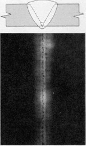
Fig. 26
Root pass aligned porosity, which involves rounded and elongated voids in the bottom tom of the weld
aligned along the weld centerline. Radiographic image: Rounded and elongated darker-
density spots, which
may be connected, in a straight line in t
he center of the width of the weld image. Welding process: GMAW.
Source: E.I. Du Pont de Nemours & Company, Inc.

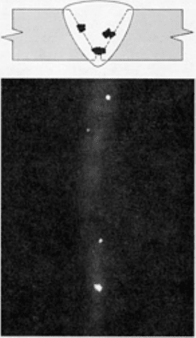
Fig. 27 Clus
ter porosity, which involves rounded or slightly elongated voids grouped together. Radiographic
image: Rounded or slightly elongated darker-
density spots in clusters with the clusters randomly spaced.
Welding process: SMAW. Source: E.I. Du Pont de Nemours & Company, Inc.
Fig. 28
Scattered porosity, which involves rounded voids random in size and location. Radiographic image:
Rou
nded spots of darker densities random in size and location. Welding process: SMAW. Source: E.I. Du Pont
de Nemours & Company, Inc.

Fig. 29
Elongated slag lines (wagon tracks), which are impurities that solidify on the surface after welding and
were not removed between passes. Radiographic image: Elongated, parallel, or single darker-
density lines,
irregular in width and slightly
winding in the lengthwise direction. Welding process: SMAW. Source: E.I. Du Pont
de Nemours & Company, Inc.
Fig. 30 Interpas
s slag inclusions, which are usually nonmetallic impurities that solidified on the weld surface
and were not removed between weld passes. Radiographic image: An irregularly shaped darker-
density spot,
usually slightly elongated and randomly spaced. Welding
process: SMAW. Source: E.I. Du Pont de Nemours &
Company, Inc.

Fig. 31 Transverse crack, which is a fracture in the weld met
al running across the weld. Radiographic image:
Feathery, twisting line of darker density running across the width of the weld image. Welding process: GMAW-
GTAW. Source: E.I. Du Pont de Nemours & Company, Inc.
Fig. 32
Longitudinal crack, which is a fracture in the weld metal running lengthwise in the welding direction.
Radiographic image: Feathery, twisting lines of darker densi
ty running lengthwise along the weld at any
location in the width of the weld image. Welding process: GMAW-
SMAW. Source: E.I. Du Pont de Nemours &
Company, Inc.

Fig. 33
Longitudinal root crack, which is a fracture in the weld metal at the edge of the root pass. Radiographic
image: Feathery, twisting lines of darker density along the edge of the image of the root pass. The twisti
ng
feature helps to distinguish the root crack from incomplete root penetration. Welding process: SMAW. Source:
E.I. Du Pont de Nemours & Company, Inc.
Fig. 34
Lack of penetration, which occurs when the edges of the pieces have not been welded together, usually
at the bottom of single-V-groove welds. Radiographic image: A darker-
density band, with very straight parallel
edges, i
n the center of the width of the weld image. Welding process: SMAW. Source: E.I. Du Pont de Nemours
& Company, Inc.

Fig. 35 L
ack of sidewall fusion, which involves elongated voids between the weld beads and the joint surfaces
to be welded. Radiographic image: Elongated parallel, or single, darker-density lines, sometimes with darker-
density spots dispersed along the LOF lines, w
hich are very straight in the lengthwise direction and not winding
like elongated slag lines. Although one edge of the LOF lines may be very straight as with LOP, lack of sidewall
fusion images will not be in the center of the width of the weld image. Weld
ing process: GMAW. Source: E.I. Du
Pont de Nemours & Company, Inc.
Fig. 36 Interpass cold lap, which involves LOF areas along
the top surface and edge of lower passes.
Radiographic image: Small spots of darker densities, some with slightly elongated tails, aligned in the welding
direction and not in the center of the width of the weld image. Welding process: GMAW. Source: E.I. D
u Pont
de Nemours & Company, Inc.

Fig. 37 Tungsten inclusions, which are random bits of tungsten fused into but not melted in
to the weld metal.
Radiographic image: Irregularly shaped, lower-
density spots randomly located in the weld image. Welding
process: GTAW. Source: E.I. Du Pont de Nemours & Company, Inc.
Slag inclusions appear along the edge of a weld as irregular or continuous dark lines on the radiograph. Voids are
sometimes present between weld beads because of irregular deposition of metal during multiple-pass welding. These
voids have a radiographic appearance that resembles slag lines.
The radiographic image of a crack is a dark narrow line that is generally irregular. If the plane of the crack is in line with
the radiation beam, its image is a fairly distinct line. If the plane is not exactly in line with the radiation beam, a faint dark
linear shadow results. In this case, additional radiographs should be taken at other angles.
Lack of penetration shows on a radiograph as a very narrow dark line near the center of the weld. The narrowness can be
caused by drawing together of the plates being welded, and the LOP may be very severe. Slag inclusions and gas holes
are sometimes found in connection with LOP and cause the line to appear broad and irregular.
The radiographic image of incomplete fusion shows a very thin, straight dark line parallel to and on one side of the weld
image. Where there is doubt, additional radiographs should be made with the radiation beam parallel to the bevel face.
This will increase the possibility of the LOF appearing on the radiograph.
Tungsten inclusions appear either as single light spots or as clusters of small light spots. The spots are usually irregular in
shape, but sometimes a rectangular light spot will appear.
Real-time radiography, which involves the display of radiographic images on television monitors through the use of
an image converter and a television camera, is a rapidly developing method for weld inspection (Ref 6). One of the main
advantages of real-time radiography for weld inspection is the cost savings that results from reducing the use of x-ray
films. However, the possibility of expanding such an inspection system to include automatic defect evaluation by the
image-processing system can yield significantly greater advantages. Automatic defect evaluation systems will result in
objective and reproducible x-ray inspection, independent of human factors. Until now, the human brain has been much
faster in analyzing and classifying the large range of flaw types found in welded joints. Computer programs for the
efficient automated evaluation of weld radiographs are currently being developed and refined. More detailed information
on the application of real-time systems for weld inspection can be found in the article "Radiographic Inspection" in this
Volume.
Ultrasonic Inspection

In ultrasonic inspection, a beam of ultrasonic energy is directed into a specimen, and either the energy transmitted through
the specimen is measured or the energy reflected from interfaces is indicated. Normally, only the front (entry) and back
surfaces plus discontinuities within the metal produce detectable reflections, but in rare cases, the HAZs or the weld itself
may act as reflecting interfaces.
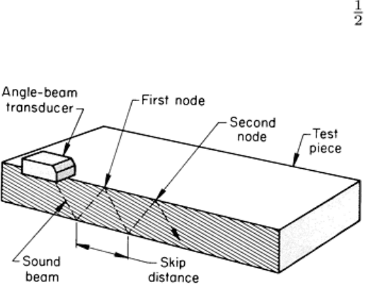
Scanning Techniques. Figure 38 shows how a shear wave from an angle-beam transducer progresses through a flat
testpiece--by reflecting from the surfaces at points called nodes. The linear distance between two successive nodes on the
same surface is called the skip distance and is important in defining the path over which the transducer should be moved
for reliable and efficient scanning of a weld. The skip distance can be easily measured by using a separate receiving
transducer to detect the nodes or by using an angle-beam test block, or it can be calculated. Once the skip distance is
known, the region over which the transducer should be moved to scan the weld can be determined. This region should
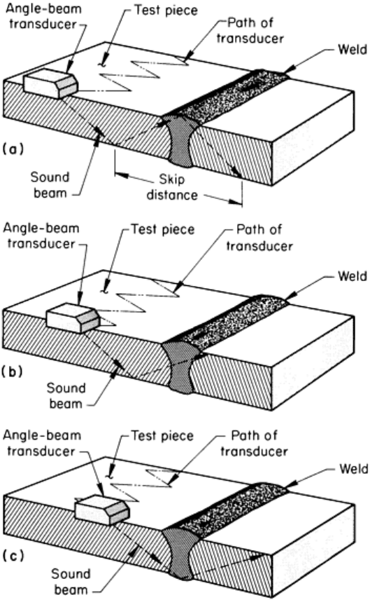
extend the entire length of the weld at a distance from the weld line of approximately to 1 skip distance, as shown in
Fig. 39. A zigzag scanning path is used, either with sharp changes in direction (Fig. 39) or with squared changes (Fig. 40).
Fig. 38 Sound beam path in a flat testpiece being ultrasonically inspected with a shear wave from an angle-
beam transducer, showing the skip distance between the nodes where the beam reflects from the surfaces

Fig. 39 Three positions of the contact type of transducer along the zigzag scanning path used during
ultrasonic
inspection of welded joints. The movement of the sound beam path across the weld is shown on a section taken
along the centerline of the transducer as it is moved from the far left position in the scanning path (a), through
an intermediate position (b), to the far right position (c).
