ASM Metals HandBook Vol. 14 - Forming and Forging
Подождите немного. Документ загружается.

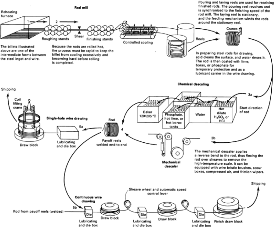
uncoiled and then re-coiled after drawing. On multiple-die continuous machines, uncoiling, drawing, and re-coiling are
repeated at successive stations. Rod coils, when ready for processing, are usually butt welded together for continuous
drawing.
Fig. 8 Schematic diagram illustrating how steel wire is drawn from rods. Source: Ref 6.
The distinction between wire and rod (or bar) is somewhat arbitrary. The term wire generally refers to smaller-diameter
products (<5 mm, or 0.2 in.) that can be rapidly drawn on multiple-die machines. Larger-diameter rod and bar stock can
be drawn on single-die machines or on benches that do not require coiling of the as-drawn product.The terms rod and wire
will often be defined from a marketing perspective. In both cases, the nature of the drawing process is similar (Ref 4).
In the drawing process, cleaned and coated coils of rod or wire are first placed on a payoff tray, stand, or reel; this permits
free unwinding of the stock. The leading end of the rod or wire, after being pointed, is then inserted through the drawing
die and seized by a gripper attached to a powered cylindrical block or capstan. On so-called dry machines, the die is
mounted in an adapter within a box. This die box contains grease, dry soap, oil, or other lubricants through which the
stock must pass before reaching the die.
Bull blocks are single-die drawing machines with individual drive systems. They are extensively used for breakdown,
finishing, or sizing operations on large-diameter rod and wire, made from both ferrous and nonferrous metals, by firms
with production requirements that do not warrant more sophisticated, continuous machines.
The spindles of these machines are generally vertical, with spindle blocks revolving in a horizontal plane. The
arrangement is occasionally reversed (with the spindles horizontal and the blocks revolving in a vertical plane),
particularly for applications involving large-diameter stock.
Many design variations are available with bull blocks. For example, a double-deck arrangement permits two drafts to be
performed, with the second draft maintaining a fixed percentage of area reduction. Other refinements include external air
cooling and internal water cooling of the block as well as riding-type block-stripping spiders for direct coiling and wire
removal. These spiders, with collapsible feet, can be equipped with automatic discharging mechanisms to transfer drawn
coils to wire carriers or stems.
The wire being drawn on the block is usually coiled around block pins that provide an extension to the height of the
block; this is often done when large bundles are not required. A stripper, with the feet temporarily collapsed, is then
inserted through the eye of the coil, with the feet fitting into stripper slots or recesses in the block flange. The feet are then
locked in their extended positions, and the bundle is lifted free of the block.
Dry-Drawing Continuous Machines. For the dry drawing of ferrous metals, four types of nonslip continuous
machines are in general use: accumulating-type machines, double-block accumulating-type machines, controlled-speed
machines, and straight-through machines.
An accumulating-type multiblock continuous wire-drawing machine is shown in Fig. 9. This machine is equipped
with electromagnetic block clutches. Photocells sense high and low wire accumulation on each block and disengage or
engage appropriate block clutches. A single dc motor drives a coupled lineshaft that carries the clutches. Only the inlet
block has to be stopped in the event of a payoff snarl, allowing the machine to continue production while the snarl is
removed. A programmable controller enables rapid checkout and simple alteration to input and output circuits, and it
serves as a continuous fault-monitoring system to simplify maintenance.

Fig. 9 Accumulating-type continuous wire-drawing machine.
Double-block accumulating machines have individually driven blocks. Wire is transferred from the first drawing
block by means of an intermediate flyer sheave that reverses the direction of the wire (without twisting it) onto a coiling
block mounted immediately above the first drawing block. The wire is then held temporarily in storage until demanded by
the second drawing block. Fully automatic, electrical drive systems can be used to start and stop, or slowdown and
speedup, the individual blocks to accumulate or deplete the wire.
On controlled-speed machines, the wire follows an essentially flat path from block to block with a constant,
unvarying amount of wire storage without twisting and slipping. A tension arm between the blocks, activated by a loop of
the wire being drawn, regulates the speed of the adjustable-speed dc motor on the preceding block.
Straight-through machines, without tension arms, are also available. The spindles are often canted from the vertical
axis to accommodate wire buildup on the blocks and to provide unimpeded, straight entry into the succeeding die; this is
usually done when large-size workpieces are required. Skillful operators are necessary because torque adjustments may
need to be altered at each block when stringing up the machines in order to make the electrical system function properly.
The continuous drawing of nonferrous rod and wire, as well as some intermediate and fine sizes of ferrous wire, is
generally done on wet-drawing slip-type machines. On these machines, the surface speed of the capstans, except for the
final (pull-out) capstans, exceeds the speed of the wire being drawn, thus creating slip of the wire on the capstans.
Brighter surface finishes are generally produced with these machines, but the machines are limited to smaller reductions
per pass than with dry-drawing nonslip continuous machines.
With wet-drawing slip-type machines, the drawing operation is generally confined to an enclosed chamber, with the
lubricant bathing the dies and wire as it is being drawn. These machines are less complicated electrically than nonslip
machines, and only one drive system is employed. They are designed with either tandem or cone-type configurations,
usually with horizontal spindles, but sometimes with a vertical spindle for the finishing capstan. Cone capstans have
drawing surfaces (usually hard-faced) that are stepped outward to provide increasing peripheral speeds. This compensates
for the elongation and increasing speed of the wire as it is reduced in diameter during drawing.
References cited in this section
4.
M.B. Bever, Ed., Encyclopedia of Material Sciences and Engineering,
Vol 2, Pergamon Press and The MIT
Press, 1986
5.
W. Wick, Ed., Forming, Vol II, 4th ed., Tool and Manufacturing Engineers Handbook,
Society of
Manufacturing Engineers, 1984
6.
Designer's Handbook: Steel Wire, American Iron and Steel Institute, 1974
Wire, Rod, and Tube Drawing
Drawing of Bar (Ref 5)
Bars about 32 mm (1.25 in.) and smaller in diameter are cold drawn from coil stock by various methods. With one
method, cold-drawn coils of rod and wire produced on the various machines described previously are straightened and cut
into bars in a separate operation on machines designed for that purpose. Some in-line methods and equipment begin by
unwinding the starting coil, then pull the stock through a draw die without recoiling, and finally straighten and cut the
material into bars in a continuous operation.
The continuous machine illustrated in Fig. 10 has a fixed die box with a recirculating wet-die lubricating system. Drawing
is accomplished with three moving grip slides; one slide for push pointing before the die box and two opposed-motion
drawing slides after the die box. The push-pointing grip runs twice as fast as the drawing grips in order to minimize
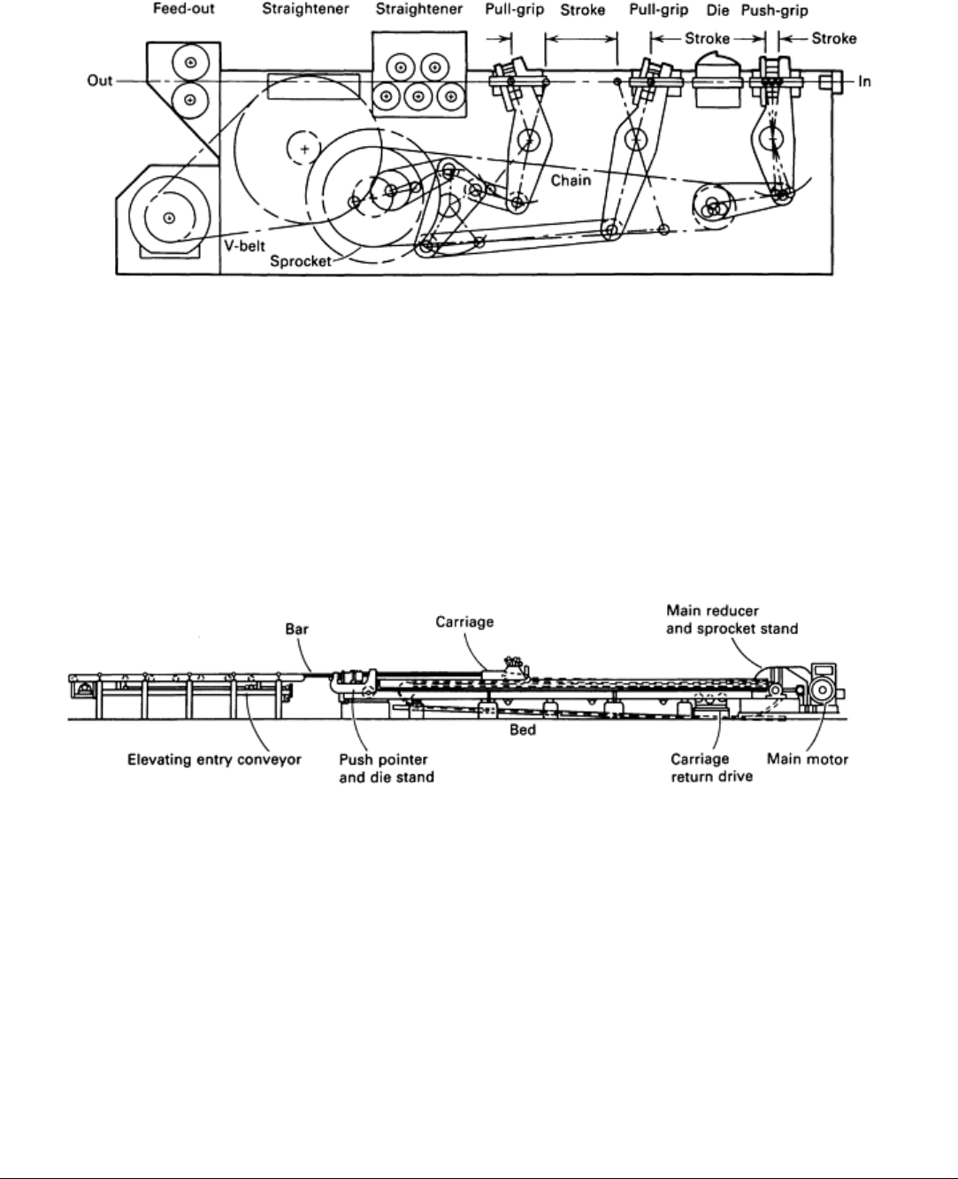
production loss when push pointing. This machine also has one set each of vertical and horizontal straightening rollers,
and a set of feed-out rolls. Most cold-drawn bars are produced from hot-rolled or extruded bars up to 17 in (55 ft) long by
152 mm (6 in.) in diameter, with seldom more than one cold-drawing pass performed.
Fig. 10 In-line drawing and straightening machine for producing cold-drawn bars from hot-
rolled steel coils or
bars.
Drawbenches for Bars. The cold drawing of cleaned and pointed hot-rolled bars is also generally performed on a
high-powered, rigidly built, long, horizontal machine called a drawbench (Fig. 11). The draw-bench consists essentially
of a table of entry rollers (an elevating entry conveyor is shown), a die stand, a carriage, and an exit rack (not shown).
Entry rollers support the hot-rolled bars and are usually powered to help bring the pointed ends of the bars into the draw
dies. An upright head can hold as many as four dies to permit the drawing of four bars at a time. If lubrication is required,
a lubricating oil system is provided on the entry side of the head.
Fig. 11 Typical arrangement of a drawbench for producing cold-drawn bars from hot-rolled bars.
On most drawbenches, the entry side of the head is provided with a hydraulic pushing device, which, for a normal draft,
can be used to push point the ends of the bars. Pneumatically operated grips on the carriage grasp the pointed ends of the
bars protruding through the dies. The carriage is powered by a motor-driven chain(s) or hydraulic piston(s) to slide or roll
along ways to pull the bar(s) through the die(s).
As soon as the bar being pulled exits the draw die, the carriage automatically releases the bar and stops. The drawn bar is
then free to fall, usually onto discharge arms for removal from the drawbench. The carriage is then rapidly returned to the
die stand--by a separately powered return system on chain benches or by means of a piston on hydraulic benches--for
drawing the next bar. Chain-operated drawbenches are usually controlled automatically to permit low speeds at the start
of the pulling action, followed by rapid acceleration to the preset pulling speed.
Reference cited in this section

5.
W. Wick, Ed., Forming, Vol II, 4th ed., Tool and Manufacturing Engineers Handbook,
Society of
Manufacturing Engineers, 1984
Wire, Rod, and Tube Drawing
Drawing of Tube (Ref 5)
Tubes, particularly those having small diameters and requiring working only of their outer surfaces, are produced from
cold-drawn coils on machines that straighten the stock and cut it to required lengths. As with bars, however, most tubes
are produced from straight lengths rather than coiled stock. With four exceptions, the methods and equipment used for
cold drawing tubes in straight lengths are basically identical to those used for bar drawing. The four exceptions are:
• Some tubes require more than one drawing pass
•
Tubes are usually longer than bars. Drawbenches for tubes are usually correspondingly longer, some
permitting drawn lengths of over 30 m (100 ft)
• Tube diameters are generally large
r than bar diameters, ranging to about 305 mm (12 in.). The bigger
tube drawbenches have larger components than do bar drawbenches
•
Tubes require internal mandrels or bars for simultaneous working or support of the interior surface
during drawing. Tube dra
wbenches are usually equipped with one of several available devices, usually
powered, for ready assembly of the cleaned, coated, and pointed workpiece onto internal bars or rod-
supported mandrels. If rod-supported mandrels are used, they are usually air-op
erated so that the
mandrel can be placed and maintained in the plane of the draw die after pulling starts. Butt or electric-
welded tubes are sometimes drawn to smooth the weld seams and tube walls
Drawing of Tubes and Cups With a Moving Mandrel. The principle of drawing with a moving mandrel is
illustrated in Fig. 6 for a single-die draw. The process can be conducted hot or cold to manufacture a variety of discrete
hollow cuplike components, such as artillery shells, shock absorber sleeves, beverage cans, and gas cylinders. Tube
drawing with a moving mandrel, often called ironing, is carried out by using several drawing dies located in tandem (Fig.
12).
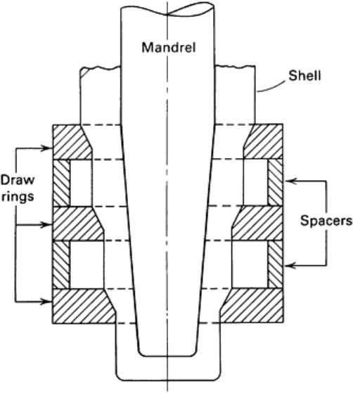
Fig. 12 Multipass ironing with tapered punch and dies in tandem.
In a typical application, a relatively thick-wall cup is first produced by extrusion or deep drawing. The wall thickness of
this cup is then reduced by tandem ironing with a cylindrical punch, while the internal diameter remains unchanged. Hot
and cold ironing both produce parts with good dimensional accuracy while maintaining or improving concentricity.
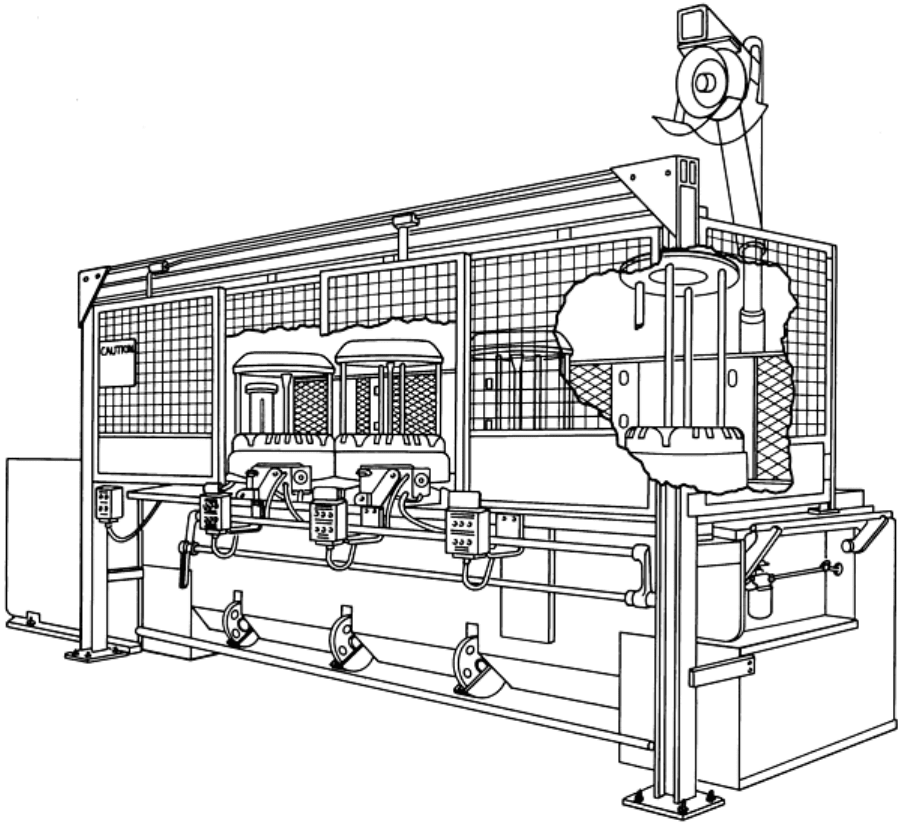
A very common application of tandem drawing is the production of beverage cans from steel or aluminum. The principle
of a can ironing press is illustrated in Fig. 13. The press is horizontal, and the ram has a relatively long stroke and is
guided by the hydrostatic bushing (A). The front seal (B) prevents mixing of the ironing lubricant with the hydrostatic
bushing oil. With the ram in the retracted position, the drawn cup is automatically fed into the press, between the redraw
die (D) and the redraw sleeve (C). The redraw die centers the cup for drawing and applies controlled pressure while the
cup is drawn through the first die (D). As the ram proceeds, the redrawn cup is ironed by passing through the carbide dies
(E), which gradually reduce the wall thickness. The ironed can is pressed against the doming punch (I), which forms the
bottom shape of the can. When the ram starts its return motion, the mechanical stripper (G), assisted by the air stripper
(F), removes the can from the ironing punch (H). The punch is made of carbide or cold-forging tool steel. The stripped
can is automatically transported to the next machine for trimming of the top edge of the can wall to a uniform height.
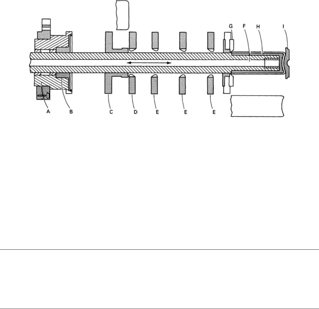
Fig. 13 Multiple-die ironing operation for the manufacture of beverage cans.
Single-Spindle Machines. With the development of floating plugs (Fig. 5), long lengths of thin-wall small-diameter
nonferrous tubing can be drawn on special types of single-spindle machines. Instead of using a conventional mandrel that
is attached to a rod, as is done in drawbench operations, a specially designed plug is inserted into the leading end of the
tube before pointing and passing the tube through the draw die. The plug is free to ride in the throat of the die during
drawing, thus controlling the inside diameter of the tube (while the die controls the outside diameter) and maintaining the
desired wall thickness.
Drawing methods and machines, particularly material-handling arrangements, are generally more sophisticated for
Single-spindle tube drawing than for the more conventional bull blocks used in drawing rod and wire. The machine
configurations available for single-spindle tube drawing include horizontal, vertical upright, and inverted vertical designs.
Reference cited in this section
5.
W. Wick, Ed., Forming, Vol II, 4th ed., Tool and Manufacturing Engineers Handbook,
Society of
Manufacturing Engineers, 1984
Wire, Rod, and Tube Drawing
Dies and Die Materials
The selection of tool materials for cold drawing metal into continuous forms such as wire, bar, and tubing depends
primarily on the size, composition, shape, stock tolerance, and quantity of the metal being drawn. The cost of the tool
material is also important and may be decisive.
Dies and mandrels used for cold drawing are subjected to severe abrasion. Therefore, most of the wire, bar, and tubing
produced is drawn through dies having diamond or cemented tungsten carbide inserts, and tube mandrels are usually
fitted with carbide nibs. Small quantities, odd shapes, and large sizes are more economically drawn through hardened tool
steel dies.
Wire-Drawing Dies. Table 1 lists recommended materials for wire-drawing dies. For round wire, dies made of
diamond or cemented tungsten carbide are always recommended, without regard for the composition or quantity of the

metal being drawn. For short runs or special shapes, hardened tool steel is less costly, although carbide gives superior
performance in virtually any application.
Table 1 Recommended materials for wire-drawing dies
Wire size Recommended die material Metal to be drawn
mm in. Round wire Special shapes
<1.57
<0.062
Diamond, natural or
synthetic
Carbon and alloy steels
>1.57
>0.062
Cemented tungsten
carbide
CPM 10V, M2, or cemented
tungsten carbide
<1.57
<0.062
Diamond, natural or
synthetic
Stainless steels; titanium, tungsten, molybdenum
and nickel alloys
>1.57
>0.062
Cemented tungsten
carbide
CPM 10V, M2, or cemented
tungsten carbide
<2.06
<0.081
Diamond, natural or
synthetic
Copper
>2.06
>0.081
Cemented tungsten
carbide
CPM 10V, D2, or cemented
tungsten carbide
<2.5 <0.100
Diamond, natural or
synthetic
Copper alloys and aluminum alloys
>2.5 >0.100
Cemented tungsten
carbide
CPM 10V, D2, or cemented
tungsten carbide
<2.06
<0.081
Diamond, natural or
synthetic
Magnesium alloys
>2.06
>0.081
Cemented tungsten
carbide
. . .
Die Life. In a wire-drawing die, the approach angle and the bearing area (Fig. 7) are both subjected to severe abrasion.
Normal die life is defined as the length or mass of metal drawn through a die that causes the bearing area of the die to
increase from minimum to maximum size. Factors that influence die wear, both singly and collectively, are drawing
speed, composition of the metal being drawn, wire temperature, reduction per pass, and hardness of the die material.
Wear often begins as an angular ring on the approach angle of the die. Die life can be increased by as much as 200% if
the die is removed and repolished at the first appearance of this ring; otherwise, die wear will accelerate. Redressing
should never shorten the length of the bearing area to less than 30% of the product diameter.
Diamond Dies. The use of diamond dies is restricted only by limitations on the sizes of available industrial diamonds
and by cost, which is extremely high for diamonds in larger sizes. These tools can outperform cemented tungsten carbide
dies by 10 to 200 times, depending on the alloy being drawn; therefore, they are cost effective despite their high unit cost.
Cemented tungsten carbide is economical for wire-drawing dies in most applications above the range of size where
diamond can be used. The softer cemented carbides, which contain about 8% Co, are less brittle and can withstand greater
stock reductions without breaking, but wear more rapidly than lower-cobalt grades.
If not damaged or broken, carbide dies can be progressively reworked to accommodate larger wire sizes. Diamond dies
can also be reworked, but greater numbers of reworkings are expected from carbide dies.
Tool steel used for wire-drawing dies should have near-maximum hardness (62 to 64 HRC) for reductions below about
20%. For greater reductions, because of the possibility of breakage, hardness should be decreased to 58 to 60 HRC, even
though the rate of wear will increase.
Die breakage is usually caused by abnormal reductions, lack of mechanical support for the insert, inadequate
lubrication, or use of a tool material that is too hard and brittle for the amount of reduction and speed. Some wear
resistance is always sacrificed to minimize breakage.
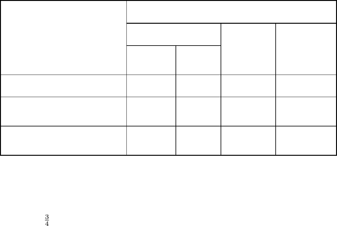
Drawing Bars and Tubing. Table 2 lists recommended die and mandrel materials for drawing bars and tubing.
Diamond is virtually never used in larger sizes; cemented tungsten carbide is recommended for three-fourths of all
applications. Tool steels are rarely used to make tools for drawing commercial-quality round bars less than 90 mm (3.5
in.) in diameter. Cemented tungsten carbide is used to draw stainless steel tubes as large as 279 mm (11 in.) in outside
diameter.
Table 2 Recommended tool materials for drawing bars, tubing, and complex shapes
Round bars and tubing
(a)
Common commercial sizes
Metal to be drawn
Bar and tube
dies
Tube
mandrels
(b)
Maximum
commercial size
(c)
:
dies and mandrels
Complex shapes: dies
and mandrels
(a)(b)
Carbon and alloy steels Tungsten carbide W1 or carbide D2 or CPM 10V
CPM 10V or carbide
Stainless steels, titanium, tungsten, molybdenum,
and nickel alloys
Diamond or
carbide
(d)
D2 or carbide D2, M2, or CPM
10V
(a)
F2 or carbide
(e)
Copper, aluminum, and magnesium alloys W1 or carbide W1 or carbide D2 or CPM 10V O1, CPM 10V, or
carbide
(a)
Tool steels for both dies and mandrels are usually chromium plated.
(b)
"Carbide" indicates use of cemented carbide nibs fastened to steel rods.
(c)
10 in. OD by in. wall.

(d)
Under 1.5 mm (0.062 in.), diamond; over 1.5 mm (0.062 in.), tungsten carbide.
(e)
Recommendations for large tubes or complex shapes apply to stainless steel only.
Drawing of Common Sizes. Common sizes are usually drawn in sufficient quantities to warrant the investment in
carbide dies. In addition, carbide bar or tube dies can be reworked to the next larger size. Die life after reworking is
substantially the same as for the first run. In drawing steel bars, it is possible to increase normal die life by properly
planning the sequence of compositions to be drawn.
For example, in drawing 0.45% C steel bars 25.40 mm (1.000 in.) in diameter, a minus tolerance of 0.08 mm (0.003 in.) is
allowed, but for this grade it is necessary to allow for a 0.05 mm (0.002 in.) elastic expansion of the bar after it passes
through the die. When the die is worn to maximum size at the bearing area, it will still be only 25.35 mm (0.998 in.) in
diameter. It is then possible to draw 0.20% C steel bars, which expand less because of their lower yield strength. After the
limit of tolerance has been reached for this grade (a diameter of 25.37 mm, or 0.999 in., at the bearing area), the die can
be used for drawing a still lower carbon steel, such as a low-carbon free-machining grade that expands even less, until the
diameter of the bearing area reaches 25.40 mm (1.000 in.). The dies can then be reworked to the next usable size.
In many cases, the planning of drawing sequences is more complicated than described above. Bell angle, approach angle,
back relief, and amount of subsequent straightening all affect as-drawn size because they influence the amount of elastic
growth that occurs; therefore, these factors must be taken into account when planning drawing sequences.
Drawing of Complex Shapes. When complex shapes are to be drawn, the selection of die material is somewhat
uncertain. In short runs less than 300 m (1000 ft), tool steels are generally more economical. For longer runs, carbide is
usually more economical unless sharp edges, which may cause the carbide to chip, are involved. In that event, tool steel
dies must be used, even though they may have to be replaced more frequently because of wear. A proprietary powder
metallurgy tool steel, CPM 10V, is another alternative to cemented carbide. CPM 10V has toughness equivalent to the
conventional tool steels D2 and M2, and it has substantially superior wear resistance in drawing-die service.
Die Breakage. The most frequent cause of die breakage in bar and tube drawing is a die design inappropriate for the
percentage of reduction. Excessive die hardness also frequently leads to breakage, particularly of dies for drawing thin-
wall tubing. Lack of lubrication, excessive drawing speeds, and other extreme conditions of operation also contribute to
die breakage.
Wire, Rod, and Tube Drawing
Lubrication (Ref 7)
Proper lubrication is essential in rod, tube, and wire drawing. No friction is needed for wire drawing, tube sinking, and
tube drawing on a fixed plug. However, some minimum friction is essential for drawing with a floating plug, and friction
is helpful on the tube/bar interface in drawing on a bar. Therefore, if at all possible, the lubricant is chosen to give lowest
friction and minimum wear. It is essential, though, that the heat generated be extracted, especially in high-speed drawing;
if this is not done, the lubricant may fail, and the properties of the wire may suffer.
In dry drawing, the lubricant is chosen for its tribological attributes, and the wire is cooled while it resides on the
internally cooled capstans of single-hole bull blocks and of multihole machines drawing with accumulation. In addition,
external air cooling of the wire coil and water cooling of the die holder are possible. If water is applied to the wire at all, it
must be totally removed before the wire enters the next die. The lubricant is usually a dry soap powder, placed in a die
box and picked up by the wire surface upon its passage through the box. This technique is used for steel wire larger than
0.5 to 1 mm (0.02 to 0.04 in.) in diameter, for which the relatively rough surface produced is acceptable. For the most
severe draws and for tubes, the soap is often preapplied from a solution, if necessary, over a conversion coating; the soap
must be allowed to dry.