ASM Metals HandBook Vol. 14 - Forming and Forging
Подождите немного. Документ загружается.

the mesh, the lower of the
z
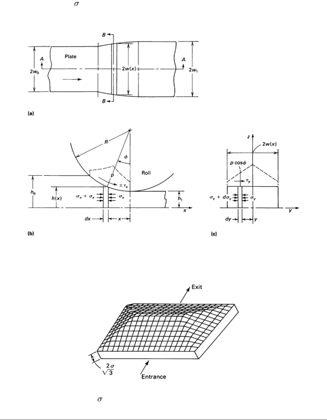
values is accepted as the actual stress. Thus, a tentlike stress distribution is obtained (Fig.
9). Integration of the stresses acting on the plane of contact gives the roll-separating force.
Fig. 8
Stress analysis of the rolling of plates. (a) Top view of the rolled plate. (b) Stresses in the rolling
direction. (c) Stresses in the transverse direction. Source: Ref 16
Fig. 9 The calculated stress (
z
) distribution in plate rolling shown three-dimensionally. Source: Ref 16.
References cited in this section
16.
G.D. Lahoti, et al., Computer Aided Analysis of Metal Flow and Stresses in Plate Rolling, J. Mech.
Work.
Technol., Vol 4, 1980, p 105
19.
S. Ekelund, in Roll Pass Design, VEB Deutscher Verlag, 1963, p 48 (in German)
20.
Z. Wusatowski, Hot Rolling: A Study of Draught, Spread and Elongation, Iron Steel, Vol 28, 1955, p 69
21.
L.G.M. Sparling, Formula for Spread in Hot Rolling, in
Proceedings of the Institute of Mechanical
Engineers, Vol 175, 1961, p 604
22.
S.-I. Oh and S. Kobayashi, An Approximate Method for Three-Dimensional Analysis of Rolling, Int.
J.
Mech. Sci., Vol 17, 1975, p 293
23.
R. Kummerling and H. Lipmann, On Spread on Rolling, Mech. Res. Commun., Vol 2, 1975, p 113
24.
H. Neumann, Design of Rolls in Shape Rolling, VEB Deutscher Verlag, 1969 (in German)
25.
R. Hill, A General Method of Analysis for Metalworking Processes, Inst. J. Mech. Sci., Vol 16, 1974, p 521
Flat, Bar, and Shape Rolling
G. D. Lahoti, The Timken Company; S.L. Semiatin, Battelle Columbus Division
Shape Rolling
Rolling of shapes, also called caliber rolling, is one of the most complex deformation processes. A round or round-
cornered square bar, billet, or slab is rolled in several passes into relatively simple sections such as rounds, squares, or
rectangles; or complex sections such as L, U, T, H, or other irregular shapes (Ref 26). For this purpose certain
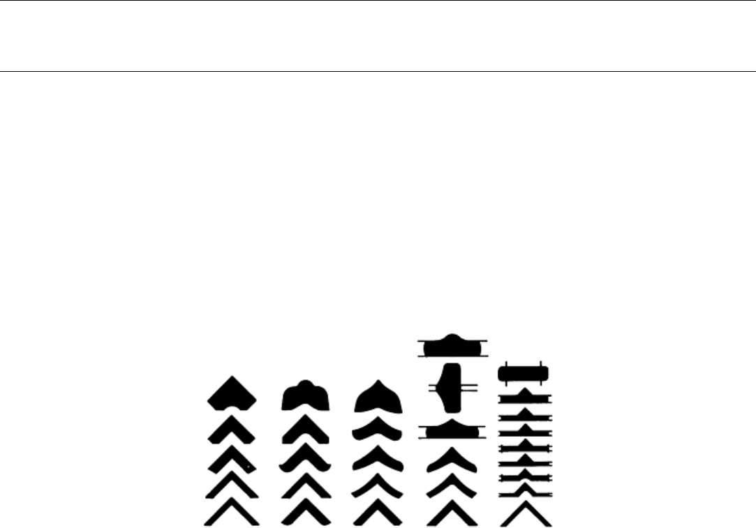
intermediate shapes or passes are used, as shown in Fig. 10 for the rolling of angle sections (Ref 27). The design of these
intermediate shapes, that is, roll pass design, is based on experience and differs from one company to another, even for
the same final rolled section geometry. Relatively few quantitative data on roll pass design are available in the literature.
Good summaries of references on this subject are given in several books (Ref 24, 26, 28, 29, 30, 31) and in a few recent
articles (Ref 32, 33).
Fig. 10 Five possible roll pass designs for the rolling of a steel angle section. Source: Ref 27.
Basically, there are two methods for rolling shapes or sections. The first method is universal rolling (Fig. 11). The second
method is caliber rolling (Fig. 10, 12). In universal rolling, the mill and stand constructions are more complex. However,
in the rolling of I-beams or other similar sections, this method allows more flexibility than does caliber rolling and
requires fewer passes. This is achieved because this method provides appropriate amounts of reductions, separately in
webs and flanges.
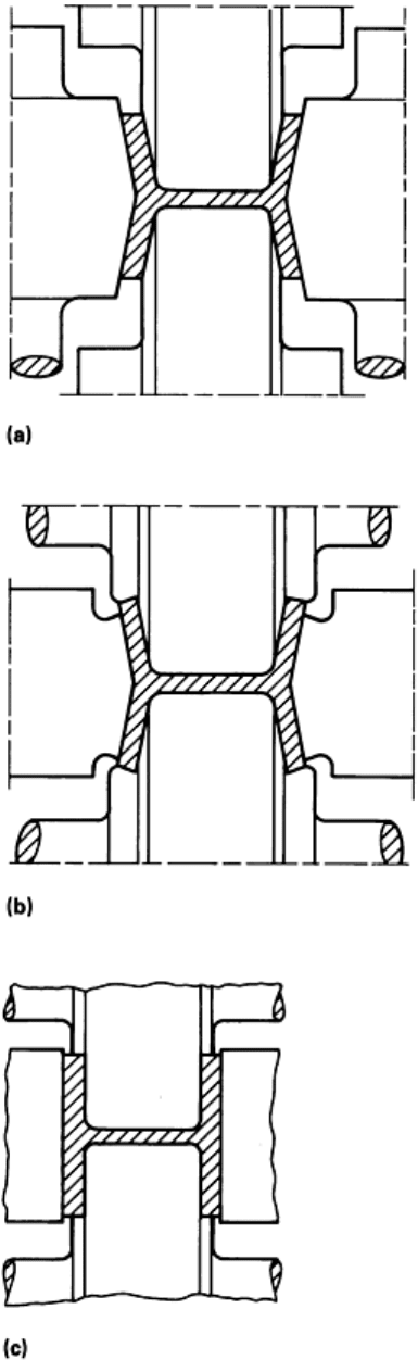
Fig. 11 Universal rolling of flanged beams. (a) Universal roll stand. (b) Edging stand. (c) Finishi
ng stand.
Source: Ref 34
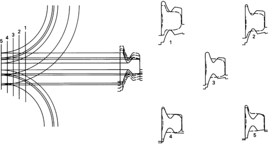
Fig. 12
Analysis of a roll stand used in rolling of rails. Sketches 1 through 5 illustrate the stock in broken lines
and the roll in solid lines at various positions in the deformation zone. Source: Ref 35
For successful rolling of shapes, it is necessary to estimate for each stand: the roll separating force and torque, the spread
and elongation, and the appropriate geometry of the roll cavity or caliber. The force and torque can be estimated either by
using empirical formulas or by approximating the deformation in shape rolling with that occurring in an "equivalent"
plate rolling operation. In this case, the "equivalent" plate has initial and final thicknesses that correspond to the average
initial and final thicknesses of the rolled section. The load and torque calculations can be performed for the "equivalent"
plate, as discussed earlier in this chapter for plate rolling. The results are approximately valid for the rolled shape being
considered.
Estimation of Elongation. During the rolling of a given shape or section, the cross section is not deformed uniformly,
as can easily be seen in Fig. 12. This is illustrated further in Fig. 13 for a relatively simple shape. The reductions in height
for zones A and B are not equal (Fig. 13a). Consequently, if these two zones, A and B, were completely independent of
each other (Fig. 13b), zone B would be much more elongated than zone A. However, the two zones are connected and, as
part of the rolled shape, must have equal elongation at the exit from the rolls. Therefore, during rolling, metal must flow
from zone B into zone A so that a uniform elongation of the overall cross section is obtained (Fig. 13c). This lateral flow
is influenced by the temperature differences that exist in the cross section because of variations in material thickness and
heat flow.
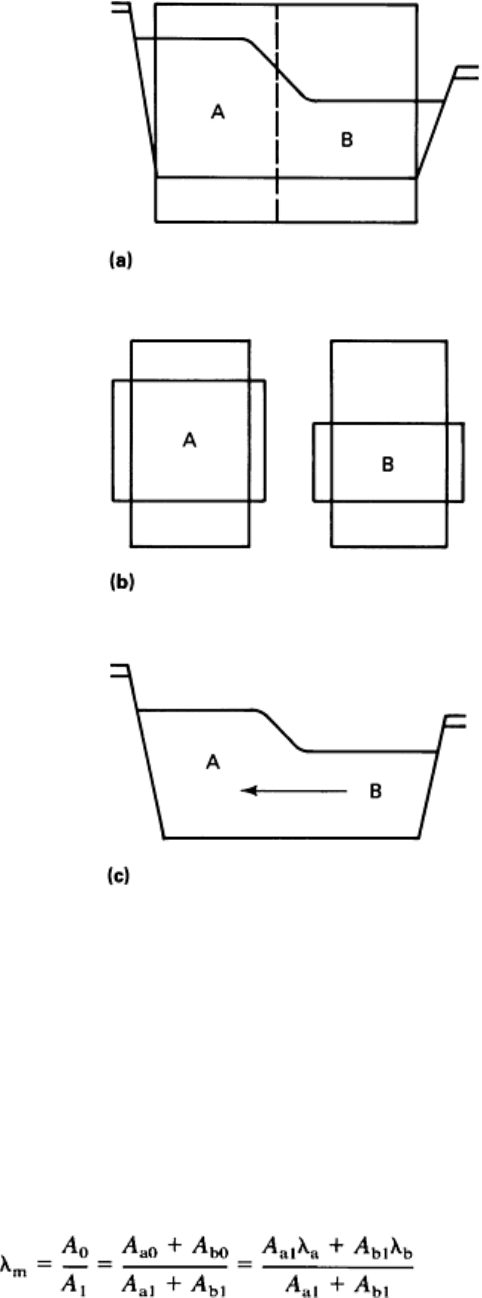
Fig. 13
Nonuniform deformation in the rolling of a shape. (a) Initial and final sections. (b) Two zones of the
section considered as separate plates. (c) Direction of lateral metal flow. Source: Ref 24
To estimate the overall elongation, it is necessary to divide the initial section into a number of "equivalent" plates (A, B,
C, and so forth), as shown in Fig. 13. The elongation for an individual section, without the combined influence of other
portions of the section, can be estimated by using both the plate-rolling analogy and the techniques discussed in this
article. The combined effect can be calculated by taking a "weighted average" of the individual elongations. For example,
if the original section is to be divided into an equivalent system consisting or two plate sections (A and B in Fig. 13), with
individual cross-sectional areas A
a
and A
b
, then the following weighted-average formula can be used:
(Eq 21)
where λ is the elongation coefficient (that is, the cross-sectional area at the entrance divided by the cross-sectional area at
the exit); A is the cross-sectional area; m is a subscript denoting average; a and b are subscripts denoting section portions
A and B; and 0 and 1 are subscripts denoting entrance and exit values, respectively.
Computer-Aided Roll Pass Design. Estimation of the number of passes and of the roll geometry for each pass is the
most difficult aspect of shape rolling. Ideally, to accomplish this, certain factors, discussed below, must be considered.
The Characteristics of the Available Installation. These include diameters and lengths of the rolls, bar
dimensions, distance between roll stands, distance from the last stand to the shear, and tolerances that are required and
that can be maintained.
The reduction per pass must be adjusted so that the installation is used at a maximum capacity, the roll stands are not
overloaded, and roll wear is minimized. The maximum value of the reduction per pass is limited by the excessive lateral
metal flow, which results in edge cracking; the power and load capacity of the roll stand; the requirement for the rolls to
bite in the incoming bar; roll wear; and tolerance requirements.
At the present stage of technology, the above factors are considered in roll pass design by using a combination of
empirical knowledge, some calculations, and some educated guesses. A methodical way of designing roll passes requires
not only an estimate of the average elongation, as discussed earlier, but also the variation of this elongation within the
deformation zone. The deformation zone is limited by the entrance, where a prerolled shape enters the rolls, and by the
exit, where the rolled shape leaves the rolls. This is illustrated in Fig. 12. The deformation zone is cross sectioned with
several planes (for example, planes 1 to 5 in Fig. 12; 1 is at the entrance, 5 is at the exit). The roll position and the
deformation of the incoming billet are investigated at each of these planes. Thus, a more detailed analysis of metal flow
and an improved method for designing the configuration of the rolls are possible. It is evident that this process can be
drastically improved and made extremely efficient by the use of computer-aided techniques.
In recent years, most companies that produce shapes have computerized their roll pass design procedures for rolling
rounds (Ref 33, 36, 37, 38, 39, 40) or structural shapes (Ref 36, 40, 41, 42, 43). In most of these applications, the
elongation per pass and the distribution of the elongation within the deformation zone for each pass are predicted by using
an empirical formula. If the elongation per pass is known, it is then possible, by use of computer graphics, to calculate the
cross-sectional area of a section for a given pass, that is, the reduction and the roll geometry. The roll geometry can be
expressed parametrically (in terms of angles, radii, and so forth). These geometric parameters can then be varied to
optimize the area reduction per pass and obtain an acceptable degree of fill of the roll caliber used for that pass.
Computer-Aided Roll Pass Design of Airfoil Sections. To analyze metal flow and predict force and torque in the
rolling of airfoils, two computer programs have been developed in a recent study (Ref 17). The first of these programs,
SHPROL, uses upper bound analysis in a numerical form to predict spread and roll torque. SHPROL is based on the
following simplifying assumptions:
•
The initial contact between the rolls and the entrance section can be approximated as a straight line.
(This is only correct if the upper and lower surfaces of the initial section already have the shape of the
rolls.)
• An airfoil shape can be considered as an aggregate of slabs, as shown in Fig. 14.
• Plane sections perpendicular to the r
olling direction remain plane during rolling. Thus, the axial velocity
(velocity in the rolling, or x,
direction) at any section perpendicular to the rolling direction is uniform
over the entire cross section.
• The velocity components in the transverse, or y, direction and in the thickness, or z,
direction are
functions of x and linear in the y and z coordinates, respectively.
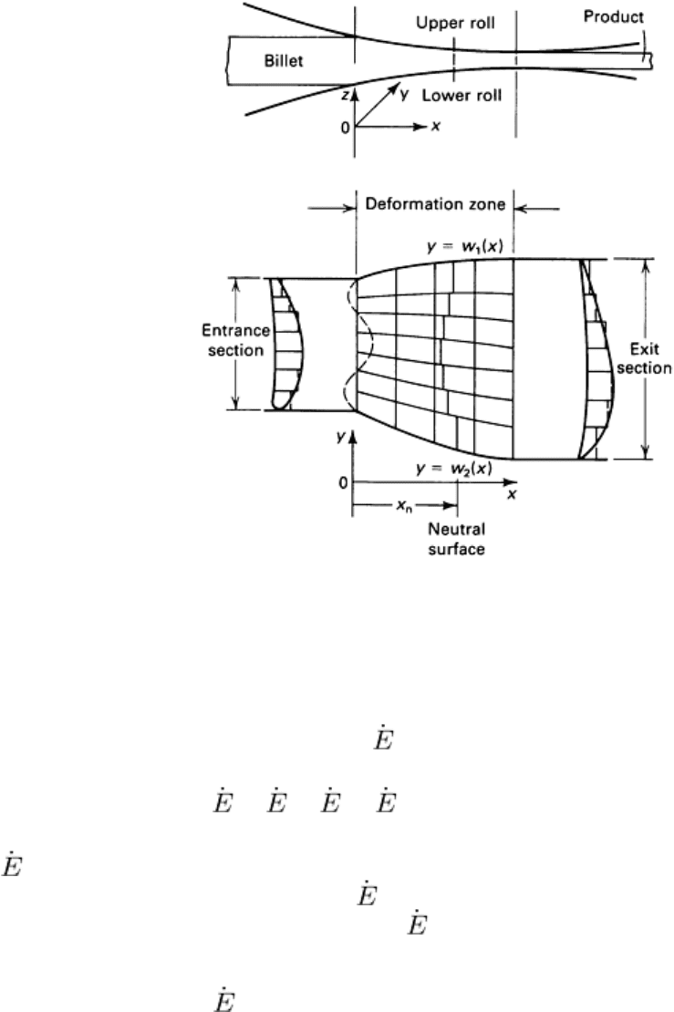
Fig. 14 Configuration of deformation zone in the application of numerical upper-
bound analysis to the rolling of
airfoil shapes. Source: Ref 17
In Fig. 14 each element is considered to be a plate for which it is possible to derive a kinematically admissible velocity
field. The total energy dissipation rate of the process
T
is:
T
=
P
+
D
+
F
(Eq 22)
where
P
is the energy rate of plastic deformation, and is calculated for each element by integrating the product of flow
stress and the strain rate over the element volume;
D
represents the energy rates associated with velocity discontinuities
and is due to internal shear between the elements; and
F
is the energy rate due to friction between the rolls and the
deforming material.
The total energy dissipation rate
T
is a function of unknown spread profiles w
1
and w
2
(Fig. 14) and the location of the
neutral plane x
n
. As in the analysis discussed earlier for plate rolling, the unknown coefficients of w
1
, w
2
, and x
n
are
determined by minimizing the total energy rate.
The computer program SHPROL uses as input data: roll and incoming-shape geometry, friction, flow stress, and roll
speed. SHPROL can predict the energy dissipation rates, the roll torque, and, most important, the amounts of elongation
and spread within one deformation zone, in the rolling of any airfoil shape.
The second program, called ROLPAS, uses interactive graphics and is capable of simulating the metal flow in the rolling
of relatively simple shapes, such as rounds, plates, ovals, and airfoils (Fig. 15). ROLPAS uses as input: the geometry of
the initial section, the geometry of the final section, the flow stress of the rolled material and the friction factor, and the
variations in elongation and spread in the rolling direction, as calculated by the SHPROL program.
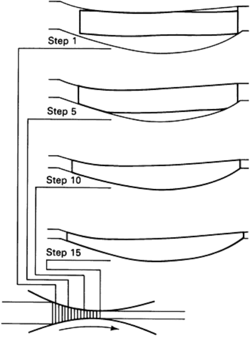
Fig. 15 Selected simulation steps as displayed by ROLPAS for a test airfoil shape cold
rolled from rectangular
steel stock
To simulate the rolling process, ROLPAS divides the deformation zone into a number of cross sections parallel to the roll
axis (Fig. 7, 15). The simulation is initiated by considering the cross-sectional area, stresses present, and the roll-
separating force and torque for the first section. These same analyses can then be performed on any succeeding section.
Computer-Aided Roll Pass Design for Round Sections. Several computer-aided methods for designing caliber
rolls for rod rolling have been discussed in the literature (Ref 33, 36, 37, 38, 39, 40). One of these methods is a computer
program called RPDROD for establishing roll cross sections and pass schedules interacting with a graphics terminal (Ref
33). RPDROD uses an empirical formula for estimating the variation of the spread in the roll bite and parametrically
described alternative roll caliber designs. When using this program, the designer obtains an optimum roll pass schedule by
evaluating a number of alternatives in which individual pass designs are selected from a variety of caliber shapes
commonly used in rod rolling.
The computer program RPDROD consists of four modules, called STOCK, SCHEDULE, GROOVE, and METAL
FLOW. The STOCK design module allows the user to design/specify the entry cross section for the first pass in the
schedule. A square, rectangular, or round stock cross section can be defined. The SCHEDULE design module allows the
user to design the roll pass schedule by providing specific functions:
• Add a new pass to the roll pass schedule, by es
timating alternative roll cross section dimensions from
design data provided by spread/elongation calculations
• Delete pass design data from the schedule in order to investigate alternative pass designs
• Review and/or provide hard copy of existing pass design data
The SCHEDULE design module allows the user to design an optimum roll pass schedule by investigating various
alternative pass design and/or shape combinations. In principle, any roll cross section shape considered by the program
could be used for a given pass in the schedule. However, RPDROD has facilities for checking input data and thus for
preventing the selection of an illogical pass design or the inappropriate selection of roll cross-sectional shape
combinations.
The GROOVE design module can be used to change the initially suggested roll cross section dimensions, as the user
deems appropriate. As in the SCHEDULE module, input checking facilities ensure that specified roll cross-sectional
dimensions are consistent with the chosen roll cross-sectional shape and bar entry cross section.
The METAL FLOW design module provides the user with details of metal flow simulation, including the calculated cross
sections of the deforming bar in the roll bite, stresses in the deforming material, roll separating load, and roll torque. For
this purpose, this module uses the ROLPAS program discussed earlier for the rolling of airfoil shapes.
As an example, a pass schedule calculated with RPDROD is given in Table 1. Comparison of these results with laboratory
experiments indicated that these predictions were reasonably accurate, and RPDROD can be used for practical roll pass
design for rolling of round sections (Ref 33).
Table 1 Summary of pass schedule information for the laboratory experiments as simulated by RPDROD
Pass
number
Groove
shape
Rotation
angle,
degrees
Exit
area,
in.
2
Exit
speed,
ft/min
Reduction
in area, %
Area
fill,
%
Roll
force,
tonf
Horse-
power
Roll
speed,
rpm
Stock Square 0.0 1.559
60.0
1 Square 45.0 1.394
55.6 10.6 93.2 5.3 1.3
30.0
2 Square 90.0 1.171
57.5 16.0 96.1 16.3 6.3
30.0
3 Square 90.0 1.042
57.7 11.0 95.7 8.7 2.5
30.0
4 Oval 45.0 0.873
59.4 16.2 98.8 14.1 6.2
30.0
5 Round 90.0 0.780
58.1 10.6 99.3 5.9 1.9
30.0
6 Oval 90.0 0.675
58.3 13.5 101.1
9.1 2.9
30.0
7 Round 90.0 0.595
59.1 11.8 98.9 4.8 1.4 30.0
Computer-Aided Roll Pass Design of Structural and Irregular Sections. Computer graphics is being used by
many companies for the design and manufacture of the caliber shapes for the rolling of structural sections (Ref 36, 40, 41,
42, 43). A publication on this subject gives an excellent summary of the practical use of computer graphics for roll caliber
and roll pass design (Ref 43). In this case, the cross section of a rolled shape is described in general form as a polygon.
Each corner or fillet point of the polygon is identified with the x and y coordinates and with the value of the
corresponding radius (Fig. 16). Thus, any rolled section can be represented by a sequence of lines and circles. This
method of describing a rolled section is very general and can define a large number of sections with a single computer
program. Lines or circles that are irrelevant in a specific case can be set equal to zero. Thus, a simpler section, with a
smaller number of corner and fillet points, can be obtained. For example, in the rolling of the symmetric-angle section
shown in Fig. 10, several intermediate section passes are required. Such an intermediate section is shown in parametric
representation in Fig. 17. In this figure, all the geometric variables can be modified to change the cross-sectional area
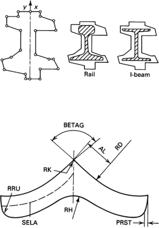
and/or the amount of reduction per pass. These variables, which fully describe this section, are SELA = length (of one
leg) at centerline, BETAG = angle at top corner, RK = radius at top corner, AL = length of straight portion at top, RD =
radius of leg at top, PRST = projection of draft angle, RRU = radius at lower tip of leg, and RH = radius at bottom corner.
Fig. 16 Geometric representation of a rolled section as a polygon. Source: Ref 43
Fig. 17 Parametric representation of an intermediate-shape rolling pass for a symmetric angle section.
See also
Fig. 18. Source: Ref 43
In establishing the final section geometry, the designer assigns desired values to the variables listed above and, in
addition, inputs the desired cross-sectional area and the degree of caliber fill, for example, the desired ratio of rolled
section area versus section area on the caliber rolls. Thus, there is only one geometric variable that is calculated by the
computer program, and that is the thickness of the leg of the angle section. In the example shown in Fig. 18(a), the leg
thickness is calculated to be 18.2 mm (0.72 in.). The designer compares this section geometry (Fig. 18a) with the caliber
geometry of the next pass that has been generated in a similar way. Let us assume that the section shown in Fig. 18(a)
appears to be too long, that is, SELA is 67.5 mm (2.66 in.) and should be reduced to 65 mm (2.56 in.) without modifying
the other variables. The interactive program is rerun with the new value for SELA. The modified section, shown in Fig.
18(b), is slightly thicker than the original section in order to maintain the same cross-sectional area.