ASM Metals HandBook Vol. 14 - Forming and Forging
Подождите немного. Документ загружается.

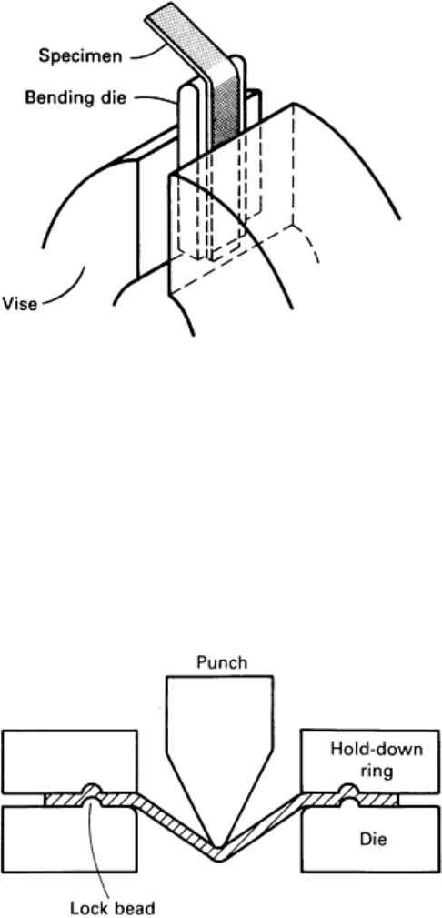
If the specimen bends through 180° without fracturing or cracking,
the experiment is repeated using a bending die of smaller radius. A
modified test is performed for highly ductile metals that have
extremely small bend radii. The specimen is initially bent at its
midpoint, through less than 90°, over a small radius. The test is then
completed by pressing the ends of the specimen together between flat
platens without a bending die placed between the platens.
The ratio of specimen width to thickness should be greater than 8 to
1, and sheared edges should be machined, filed, or sanded to remove
the heavily cold-worked metal present. The orientation of the
specimen with respect to the rolling direction may be important
because it affects the resistance of the specimen to fracture.
Specimens cut perpendicular to the rolling direction usually require a
larger bend radius and therefore provide a more conservative measure
of this property.
For low-carbon sheet steels, the minimum bend radius is usually not a
limiting factor. For high-strength steels and aluminum alloys, it
sometimes is, and methods such as rope hemming, which increase the
bend radius, have been developed to prevent cracking during the hemming of these materials.
Stretch-Bending Tests. A rectangular strip of sheet metal is clamped at its ends in lock beads and deformed in the
center by a punch, as shown in Fig. 20. There are two types of stretch-bending tests: the hemispherical test, in which a
hemispherical-tipped punch and a concentric circular lock bead are used, and the angular test, in which a wedge-shaped
punch and straight parallel lock beads are used. The hemispherical test involves a range of strain states. The angular test
produces the plane-strain state.
The punch travel between initial contact and specimen fracture
is measured. The conditions are chosen so that fracture occurs in
the region of punch contact. When fracture occurs in the
unsupported region, which tends to happen with narrow thin-
gage specimens and large punch radii, the test effectively
becomes a tensile test.
The results of several hemispherical and angular stretch-bending
tests on three types of steels and an aluminum alloy have been
reported (Ref 48). For the hemispherical test, the effects of
variations in punch tip radii ranging from 3.2 to 51 mm (0.13 to
2.0 in.), in sheet thicknesses ranging from 0.5 to 3.3 mm (0.02 to
0.13 in.), and in specimen widths ranging from 25 to 203 mm
(1.0 to 8.0 in.) were investigated in the dry and lubricated
conditions. The tests showed that the height at fracture increased
with increasing punch radius and sheet thickness and with the
use of lubricants. It decreased with increasing specimen width in
the range of 102 to 203 mm (4.0 to 8.0 in.), in which fracture occurred in the region of punch contact. The ranking of two
of the steels was found to be dependent on specimen thickness.
Fewer conditions were investigated in the angular test. The results for a 76 mm (3.0 in.) wide specimen and punch radii
ranging from 1.6 to 6.4 mm (0.06 to 0.25 in.) showed much greater heights than for the same conditions in the
hemispherical test. Increases in height with increasing punch radius were also evident, but in contrast to the hemispherical
case, a decrease with increasing thickness was observed. Preliminary correlation between the results of these tests and
production experience is reported to be fairly good.
Data from the angular stretch-bending test have been analyzed and indicate that fracture occurs at a constant limit strain
that is independent of sheet thickness and punch radius (Ref 49). Stretch-bending tests are useful for material selection
and for predicting the effects of material substitution and gage reduction in many forming operations.
Fig. 19 Schematic of simple bending test.
Fig. 20 Schematic of stretch-bending test.
Stretching Tests
Historically, ball punch tests, such as the Olsen cup test and Erichsen cup test, have been used to determine the properties
of sheet metals in stretching. These tests stretch a specimen over a hardened steel ball and measure the height of the cup
produced. More recently, tests that stretch the specimen over a much larger hemispherical dome have been developed,
including the limiting dome height test, which uses specimens of different widths to control the strain ratio at fracture.
Many forming operations involve stretching an edge of a part or a cutout (hole) in a part. For example, when a concavely
contoured edge is flanged, the metal is stretched. The ability of the material to undergo this type of forming operation can
be measured by the hole expansion test. In this test, a cylindrical, hemispherical, or conical punch is pushed through a
circular hole of smaller diameter in the specimen. This initially increases the diameter of the hole and then forms a rim of
stretched metal. The edge ductility of the material is indicated by the amount of hole expansion that occurs without edge
cracking.
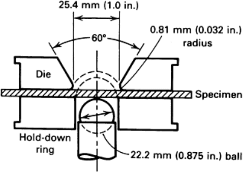
Ball Punch Tests. The Olsen and Erichsen cup tests are similar, differing principally in the dimensions of the tooling
used. The Olsen test (ASTM E 643) uses a 22.2 mm (0.875 in.) diam hardened steel ball and a die with a 25.4 mm (1.0
in.) internal diameter (28.6 mm, or 1.125 in., for gages over 1.5 mm, or 0.06 in.) and a 0.81 mm (0.032 in.) die profile
radius, as shown in Fig. 21. The Erichsen test, which is extensively used in Europe, uses a 20 mm (0.79 in.) diam ball and
a die with a 27 mm (1.06 in.) internal diameter and a 0.75 mm (0.03 in.) die profile radius.
In both tests, the cup height at fracture is used as the measure of
stretchability. The preferred criterion for determining this point is
the maximum load. When this cannot be determined, the onset of
a visible neck or fracture can be used, but this yields a slightly
different value. The cup height measured by means of a visible
fracture is 0.3 to 0.5 mm (0.012 to 0.020 in.) greater than the
height measured at the maximum load.
These tests, as indicators of stretchability, should correlate with
the n value, but the correlation is not satisfactory. Improved
correlations with the total elongation (Ref 50) and reduction in
area (Ref 51) have been reported. Some investigators have
reported poor reproducibility of results in the Olsen and Erichsen
tests and poor correlation with production experience (Ref 52,
53). Satisfactory reproducibility and correlation in specific cases
have been reported when experimental conditions were carefully
controlled (Ref 50).
The variability in tests has been attributed to the small size of the
penetrator, uncontrolled drawing-in of the flange, and inconsistent lubrication (Ref 52, 53). The small size of the
penetrator leads to excessive bending, particularly in thicker sheet, and is generally unrepresentative of production
conditions. Drawing-in can be controlled somewhat by standardizing the specimen size and by using a high (~71 kN, or
~8 tonf) clamping force. Even greater control can be achieved by using lock beads or serrated dies (dies with concentric
circular ridges of triangular cross section that dig into the specimen and prevent slippage).
Consistent lubrication can be achieved by using oiled polyethylene between the specimen and penetrator. The problems
with the Olsen and Erichsen tests have led to the development of stretching tests that use a much larger diameter punch
and a lock bead to prevent drawing-in.
Hemispherical dome tests using 50.8, 76.2, and 101.6 mm (2.0, 3.0, and 4.0 in.) punches have been reported (Ref
52, 53). A 100 mm (3.94 in.) test is the most widely used. Typical tooling designed for this test is shown in Fig. 22. The
lock bead, in combination with a hold-down force of about 222 kN (25 tonf), completely prevents drawing-in of the
flanges.
Fig. 21 Schematic of Olsen cup test.
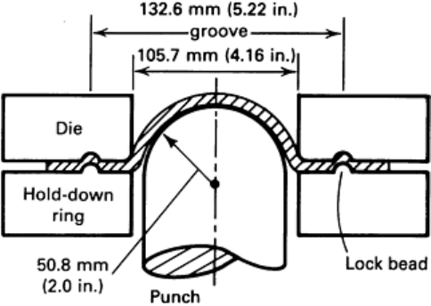
The specimens fracture circumferentially at a distance (for
lightly lubricated low-carbon steel) of 35 to 40 mm (1.38
to 1.57 in.) from the pole, at which point the radial strain
peaks sharply. The circumferential strain varies gradually
from a maximum of 10 to 20% at the pole to zero at the
lock bead.
The hemispherical dome test yields more reproducible
results than the Olsen and Erichsen cup tests. For low-
carbon steels, the dome height, which is measured at the
point of maximum load, increases linearly with the n
value. For a wide range of material (including brasses,
aluminum alloys, and zinc), optimal correlation is found
between the dome height and the total elongation, which
incorporates the effects of strain rate hardening and
limiting strains.
Overall, the use of lubrication in hemispherical dome tests
is beneficial. A thin layer of a standard lubricant, applied
in a consistent manner, reduces scatter in test results,
simulates production conditions more closely, reduces damage to the tooling, and simplifies specimen preparation. The
improved sensitivity obtained in the dry condition is negated by the increased scatter in the results.
The use of lubrication makes the strain ratio at fracture more biaxial. This is undesirable for production simulation,
because most production failures occur in the region of plane strain, that is, in a less biaxial manner. To control the strain
ratio at fracture, specimens of different widths were used (Ref 54). This technique has been developed further into the
limiting dome height test (Ref 55, 56).
Limiting Dome Height (LDH) Test. Specimens of various widths are held in a circular lock bead and stretched over
a 100 mm (3.94 in.) dome using tooling of the type shown in Fig. 22. In principle, this test can be used to duplicate a large
range of production failure strain states and to select the most suitable material for each particular operation. In practice,
most production failures occur close to plane strain, which is generally the strain state at the minimum on a plot of dome
height versus specimen width. Consequently, attention has concentrated on this minimum value.
When testing a new material, initial tests should be performed to determine the specimen width that yields the minimum
dome height, or LDH value, and the corresponding minor strain. Once this has been established, tests can be conducted at
this width only. For low-carbon steels, the minimum dome height occurs at a width of approximately 124 mm (4.9 in.).
This can also be used as an approximation for other materials. Increments in test specimen width of ±3 mm (±0.12 in.) are
sufficiently close.
It has been found that, for specimens lubricated lightly with a wash oil, the dome height increases with decreasing hold-
down force below about 250 kN (28 tonf). This is attributed to the drawing-in of the flange. Therefore, a hold-down force
of at least 250 kN (28 tonf) should be used. The limiting dome height is taken as the height at which the maximum load
occurs.
Preliminary tests have shown a correlation between the limiting dome height test and production stamping performance
(Ref 57). Some problems have been encountered with test reproducibility over a period of time and among different test
facilities. Numerous attempts have been made to determine a correlation between the limiting dome height test and
mechanical and forming property measurements. The dome height depends on the ability of the material to distribute
strain and on the limiting strain level and would therefore be expected to correlate with the total elongation. Correlation
for a range of different materials has been reported (Ref 58).
The specimens used in the limiting dome height test can be sheared or blanked from the sheet sample, and the test can be
performed rapidly on equipment that automatically measures the dome height at the maximum punch load. The test has
considerable potential for production control and research applications.
Hole Expansion Test. A flat sheet specimen with a circular hole in the center is clamped between annular die plates
and deformed by a punch, which expands and ultimately cracks the edge of the hole. Flat-bottomed hemispherical and
Fig. 22
Tooling for the 101.6 mm (4.0 in.)
hemispherical dome test. Source: Ref 52.
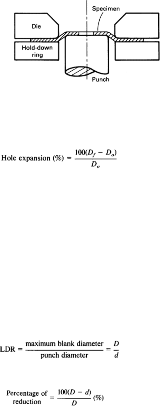
conical punches have been used, and in some cases die plates have been equipped with lock beads to prevent drawing-in
of the flange. The punch should be well lubricated and should have a large profile radius. A spacer can be used between
the punch and the sample, as in the Marciniak test. Figure 23 illustrates the hole expansion test using a flat-bottomed
punch.
Fig. 23 Schematic of the hole expansion test with a flat-bottomed punch.
The test is terminated when a visible crack is observed, and the hole expansion is expressed as the percentage of increase
in hole diameter:
(Eq 25)
where D
o
and D
f
are the initial and final hole diameters, respectively.
The results of several hole expansion tests on eight different types of steel are reported in Ref 59. Square specimens
measuring 203 mm (8.0 in.) on each side with a 25 mm (1.0 in.) diam punched hole, a 101.6 mm (4.0 in.) diam
hemispherical punch, and die plates with a 2 mm (0.08 in.) radius lock bead were used. The measured hole expansion
ranged from 24 to 82% for steels with yield strengths ranging from 253 to 537 MPa (36.7 to 77.9 ksi).
In most cases, removing the burr and cold-worked metal from the edge of the punched hole increased the hole expansion
considerably. The hole expansion also increased with increasing total elongation and r
m
value and decreased with
increasing tensile strength (which was anticipated, because total elongation decreases with increasing tensile strength).
Inclusions were observed in crack locations, and inclusion shape control improved hole expansion performance.
Drawing Test
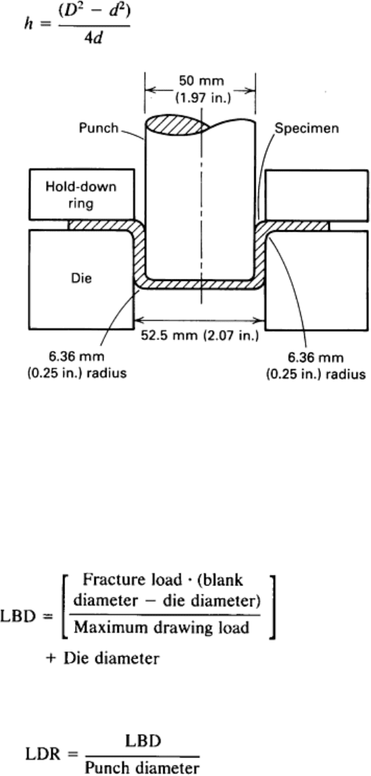
Swift Cup Test. The most commonly used test for deep drawability is the Swift cup test. Circular blanks of various
diameters are clamped in a die ring and deep drawn into cups by a flat-bottomed cylindrical punch. The standard tooling
for this test is shown in Fig. 24. Drawability is expressed as either the limiting draw ratio (LDR) or the percentage of
reduction. The limiting draw ratio is the ratio of the diameter, D, of the largest blank that can be successfully drawn to the
diameter, d, of the punch:
(Eq 26)
Percentage of reduction is defined as:
(Eq 27)
Cup height, h, is approximately (Ref 60):
(Eq 28)
Fig. 24 Standard tooling for the Swift flat-bottomed cup test.
An alternative method for determining the limiting draw ratio uses blanks of a single diameter, which is less than the
critical diameter in the standard test (Ref 61). The blanks are drawn to the maximum load, which usually takes place
before 50% of the draw has occurred. The clamping force is then increased to prevent further drawing-in of the flange,
and the load is increased to the point of fracture. The limiting blank diameter (LBD) is defined by:
(Eq 29)
The limiting draw ratio is given by:
(Eq 30)
This method has been shown to correlate well with the standard test for a range of materials of widely different
drawability (Ref 61).
The limiting draw ratio increases with normal anisotropy (r
m
) and thickness, particularly at the low ends of the ranges for
these variables, but is not sensitive to the n value (Ref 62). The limiting draw ratio also increases as the punch profile
radius increases up to about eight times the sheet metal thickness, as the die profile radius increases up to about 12 times
the metal thickness, and as the punch speed increases. The height of the ears formed in this test is proportional to the ∆r
value.
Too low a blankholder force may cause wrinkling, and too high a blankholder force may cause fracture at the punch
profile radius. The die rings should be well lubricated, but the punch should not be lubricated. By not lubricating the

punch, the amount of stretching that occurs over the punch profile radius and the tendency for splitting to occur at this
location are reduced.
Stretch-Drawing Tests
Many forming operations involve stretching and drawing; for example, square cups have drawn corners and stretched
sides. The ratio of stretching to drawing in an actual part can be measured by a shape analysis technique (Ref 63). A line
is drawn from a reference point (for example, the center of the blank) to the edge of the blank, through the critical
forming area. After forming, the ratio of the increases in length of this line inside and outside the initial die contact line is
taken as the ratio of stretching to drawing. Two tests are commonly used for stretch-drawing: the Swift round-bottomed
cup test and the Fukui conical cup test.
The Swift round-bottomed cup test resembles the Swift flat-bottomed cup test described above. However, the top
of the punch is hemispherical, which causes stretching in the center of the specimen in addition to the drawing-in of the
flange to produce the wall of the cup.
This test was used to evaluate 50 different steels with a 50 mm (1.97 in.) diam punch and 127 mm (5.0 in.) diam
specimens and with a 65 mm (2.56 in.) diam punch and 165 mm (6.5 in.) diam specimens (Ref 64). Hold-down forces of
490 and 981 N (110 and 220 lbf), respectively, were used at a test speed of 1 mm/s (0.04 in./s). Both sides of the
specimens were lubricated with thin polyethylene sheet.
The end point of the test is determined by observing fracture visually or by detecting a drop in the punch load. Multiple
regression analysis of the test results showed that the cup height at fracture increased linearly with increases in the r
m
value, n value, and metal thickness.
To determine the correlation between performance of the steels in the stretch-drawing test and in actual parts production,
4 automotive stampings were made, using 12 different steels for each. The Stampings had stretch-to-draw ratios ranging
from approximately 1 to 5 to 2 to 1, and minor-to-major strain ratios in critical areas ranging from -0.3 to +0.45. The
correlation coefficients between the test and stamping results had an average value of 0.92 and ranged from 0.89 to 0.94
(a value of 1.00 indicates perfect correlation). In another trial on a stamping with a stretch-to-draw ratio of 4.5 to 1, the
test results did not correlate. These tests indicate that for parts that involve both stretching and drawing, without excessive
stretching, the Swift flat-bottomed cup test is useful as a quality control tool.
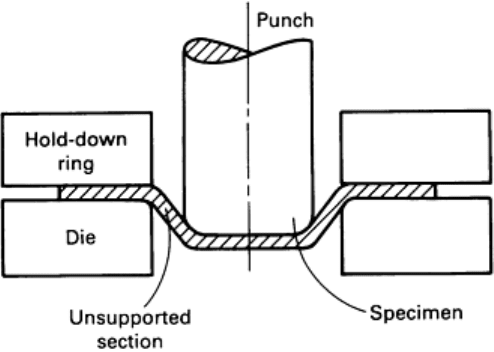
Fukui Conical Cup Test. In the Fukui conical
cup test, circular specimens punched from a
sample of sheet metal are deformed into conical
cups by means of a 12.5 to 27 mm (0.5 to 1.1 in.)
diam ball and tooling of the type shown in Fig.
25 (Ref 62, 65, JIS Z 2249). The ball size
depends on the sheet thickness. The specimens
are lubricated on the die side only. Lubrication on
the punch side leads to tilting of the specimens.
Specimens are centered and held in place by the
hold-down ring and deformed to fracture by the
punch.
The diameter of the base of the conical cup
formed is measured and divided by the diameter
of the original specimen to give the Fukui conical
cup value. The end point of the test is not critical,
because the diameter of the cone does not change
after fracture. A constant punch travel is usually
used. When the test material has a high level of
planar anisotropy (a high ∆r value), the conical
cup is asymmetric, and an average diameter must be determined. A high correlation between the Fukui conical cup value
and the product of the average n value and the average r value has been reported for low-carbon steels (Ref 62).
Fig. 25 Schematic of the Fukui conical cup test. Source: Ref 62.
An alternative method has been developed for performing this test (Ref 50). The punch travel between the initial contact
with the specimen and the onset of a drop in the punch load, which coincides with the formation of a visible neck, is
measured and used instead of the ratio of the diameters. This value, known as the formability index, correlates with the
uniform elongation and therefore with the n value for low-carbon steels.
Wrinkling and Buckling Tests
Two principal types of tests are used for wrinkling and buckling: the conical cup wrinkling test and the Yoshida buckling
test. The conical cup wrinkling test is similar to the Swift flat-bottomed cup test, but uses a punch that is much smaller
than the die opening. Consequently, the cup wall is conical and is not in contact with the punch. Under some conditions,
wrinkles form in the cup wall. In the Yoshida buckling test, a flat, square specimen is stretched slightly in the diagonal
direction, and the height of the buckle that is formed is measured (Ref 66).
Conical Cup Wrinkling Test. A circular blank is clamped between annular dies and deformed by a flat-bottomed
punch with a diameter that is typically about 75% of the internal diameter of the die. This procedure is illustrated in Fig.
26. At very low levels of hold-down force, wrinkling occurs in the flange. At higher levels, flange wrinkling is
suppressed, but wrinkling occurs in the unsupported wall. This is caused by compressive stresses in the circumferential
direction (hoop stresses) that are due to the local reduction in diameter as drawing progresses. For example, with a 75 mm
(2.96 in.) diam punch and a 100 mm (3.94 in.) diam die, the top of the wall has a diameter of 100 mm (3.94 in.). If the cup
depth is doubled, the original top of the wall becomes the new midpoint and must decrease in diameter to 87.5 mm (3.44
in.).
Fig. 26 Schematic of the conical cup wrinkling test.
At high levels of blankholder force, the tensile stresses in the radial direction in the wall prevent the formation of
wrinkles, and fracture at the punch or die radius becomes the limiting factor. The maximum cup height occurs at the
intersection of the wall wrinkling and fracture limits, as shown in Fig. 27.
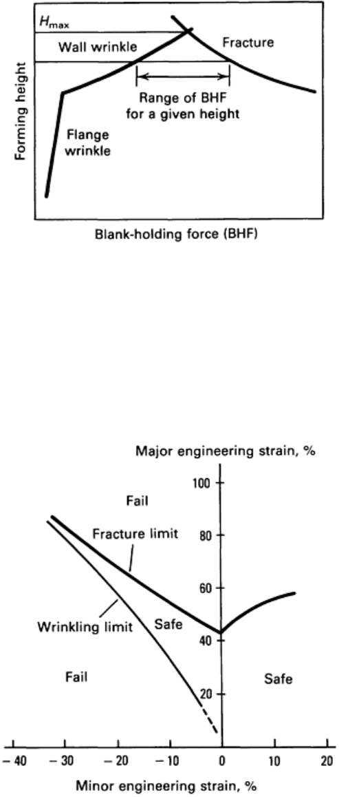
Fig. 27 Wrinkling and fracture limits in conical cup drawing. Source: Ref 67.
The results of experiments on several types of steel with different thicknesses and tooling of various dimensions have
been reported in Ref 13 and 68. Wrinkling occurred in the unsupported wall when the true compressive hoop strain
exceeded a certain value for each level of the tensile radial strain for all tooling geometries and forming conditions. The
critical wrinkling strains were plotted on the forming limit diagram, as shown in Fig. 28.
Fig. 28 Combined forming and wrinkling limit diagram. Source: Ref 68.
Attaining the critical wrinkling strain is strongly influenced by the dimensions of the specimen and tooling, lubrication,
and the hold-down force. Changes in these variables that reduce the radial stress (that is, an increase in the die radius,
improved lubrication, or a reduction in the blank diameter or the hold-down force) increase the tendency toward wrinkle
formation.
Material properties that affect wrinkling in the conical cup test are the r
m
, ∆r, and n values and the ratio of the flow stress
to the elastic modulus. A high r
m
value and low ∆r value reduce wrinkling, which initiates in the directions of lowest r
value. A high n value enables the hold-down force to be increased, which increases the radial force and reduces
wrinkling. A low flow-stress-to-elastic-modulus ratio also reduces wrinkling.
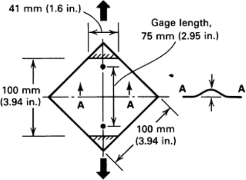
Yoshida Buckling Test. A flat, square specimen is gripped at opposite corners and pulled in tension in the diagonal
direction, as shown in Fig. 29 (Ref 66, 67). The standard specimen is 100 mm (3.94 in.) square with 41 mm (1.6 in.) wide
grips and a gage length of 75 mm (2.95 in.). The buckle height is measured over a 25.4 mm (1.0 in.) width at the center of
the specimen.
Nonuniform stresses are generated in the
specimen, and these stresses cause a buckle to
form in the center along the direction of loading.
The height of the buckle at a given elongation, for
example, 2%, is used as the measure of buckling.
Several investigations have been conducted on the
correlation between buckle height and test
material properties. The Yoshida buckling test
and a conical cone wrinkling test (using a
hemispherical punch) were performed on several
ferrous and nonferrous materials in different
tempers (Ref 69). A direct correlation for both
tests between the buckling or wrinkling height
and the yield strength, an inverse correlation with
the work-hardening exponent, and a lack of
correlation with the normal anisotropy were
reported. The Yoshida test was not successful for
aluminum, because the specimens fractured
before buckling.
The Yoshida test was performed on 31 steels of different types and thicknesses, and correlations between the slope of the
buckle height versus elongation curve, which is easier to determine than the height at a particular elongation, and the yield
strength and the ratio of yield strength to tensile strength were obtained (Ref 14). An inverse correlation with the
instantaneous (2%) strain-hardening exponent and a lack of correlation with the uniform elongation and normal
anisotropy were also noted.
Springback Tests
Springback tests that bend a specimen about a mandrel and determine the change in the angle of bending upon removal of
the bending load have been used as indicators of yield strength. This test was developed with a 12.5 mm (0.5 in.) radius
mandrel, as shown in Fig. 30, for use as a quality control tool with sheet materials with thicknesses ranging from 0.15 to
0.38 mm (0.006 to 0.015 in.) (Ref 70). Previously, hardness measurements had been used for this purpose, but they were
found to be insufficiently accurate for hard thin-gage steels and aluminum alloys, and they did not provide any
information on anisotropy.
Fig. 29 Schematic of the Yoshida buckling test. Source: Ref 67.
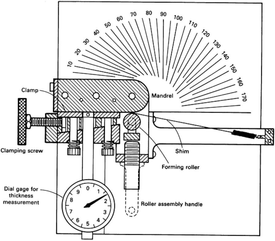
Fig. 30 Springback tester for determining yield strength. Source: Ref 70.
In the test, specimens are bent through 180° and released, and the angle of springback is read on the scale. The yield stress
can then be determined from the springback angle and material thickness by means of a previously determined
nomograph. Springback depends on the elastic modulus, which necessitates different nomographs for materials with
different moduli. The test is most accurate in the range of springback angles of 60 to 120° and should be modified by
changing the mandrel radius if the angle is less than 30° or greater than 150°.
The nomograph was calculated assuming an elastic/perfectly plastic stress-strain relationship, which is the same in
tension and compression (that is, zero strain hardening and no Bauschinger effect). This calculation has been refined by
using an average of the experimentally determined tensile and compressive stress-strain curves, including strain hardening
(Ref 71). This improves the average ratio of the yield strength predicted using springback measurements to the tensile test
yield strength from 0.80 to 0.91.
More recently, a similar test was developed that uses a larger-radius mandrel (19 mm, or 0.75 in.) (Ref 72). Twenty steels
with thicknesses ranging from 0.56 to 2.36 mm (0.022 to 0.093 in.) and with tensile strengths ranging from 293 to 710
MPa (41.6 to 103.5 ksi) were tested. The measured springback correlated better with the forming strength, which is the
average of the yield and tensile strengths, than with the individual strength values. For the same forming strength, steels
with high (>1.5%) levels of yield point elongation develop less springback than those without. In these cases, the tangent
modulus is almost zero in the region of yield point elongation.
Springback after a 90° flanging operation has been measured as a function of material flow stress, thickness, degree of
cold work, and die radius and clearance for a low-carbon steel, two high-strength low-alloy steels, and a dual-phase steel
