ASM Metals HandBook Vol. 14 - Forming and Forging
Подождите немного. Документ загружается.

Springback must be considered in bending such materials as stainless steel, phosphor bronze, certain grades of brass and
beryllium copper, or high-carbon steel. Adjustments can be made in the forming tools to provide the amount of
overbending required for the accuracy of the finished work.
More than one piece can be made in each cycle of a multiple-slide machine. For example, a part that had been made in
seven conventional press operations was replanned for the multiple-slide production of four pieces per cycle at 200 cycles
per minute.
Forming of Steel Strip in Multiple-Slide Machines
Revised by Deborah A. Blaisdell, The U.S. Baird Corporation
Multiple-Slide Machines
Multiple-slide machines are made in a range of sizes, all similar in construction and principle. The larger machines have a
longer die space, which enables more die stations to be used for the manufacture of complicated components. Generally,
the number of strokes per minute decreases and the horsepower increases as the machine size increases.
The four forming slides of a typical multiple-slide machine are generally sufficient for ordinary part-forming needs.
However, complex parts can be formed at two or three levels around the center post, thus doubling or tripling the number
of forming positions available.
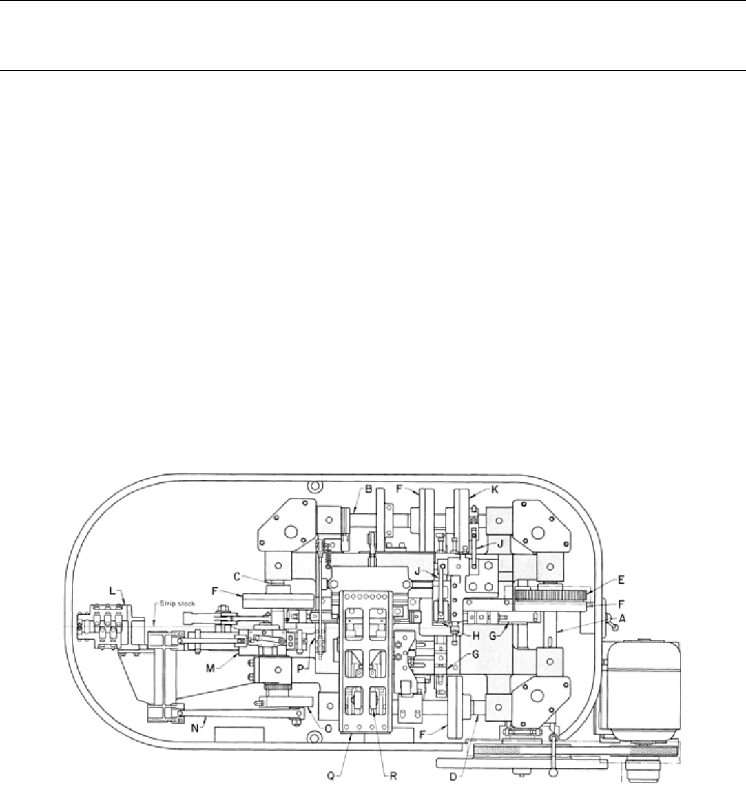
Figure 1 shows a plan view of the main units of a medium-size multiple-slide machine that uses a floor space of 3.7 × 1.5
m (12 × 5 ft), including the stock reel. Four shafts (A, B, C, and D), mounted to a flat-top bedplate, are driven at equal
speed through spur gearing (E) by an electric motor. Each of the four shafts is fitted with a positive-action cam (F) that
drives a slide (G) (only two of four are identified) on which the forming tools can be secured. In the center of the machine
is a vertical post (H) into which the center post or former is fixed and around which the work material is bent. The formed
workpiece is removed from the center post by a stripper mechanism, which usually consists of a hardened steel plate
surrounding the center post and secured to a vertical rod operated by a cam (F) on the right-hand shaft to give up-and-
down motion to the stripper. All of these parts constitute the forming station of the machine.
Fig. 1 Plan view of a multiple-slide machine showing major components. A to D, integrated shaft
s; E, spur
gearing; F, positive-
action cam; G, slide; H, vertical post; J, bell crank; K and R, cams; L, stock straightener;
M, automatic gripper in feed slide; N, links; O, adjustable crank; P, stationary gripper with cam-
operated jaws;
Q, horizontal press with dies; R, cam. See text for description of operation.
To the left of the machine proper is a stock straightener (L), shown in working position with strip stock passing through it.
Intermittent feeding of the work metal is accomplished by an automatic gripper in the feed slide (M) and an adjustable
crank (O), which is attached to a shaft (C). A separate gripper (P) is provided with cam-operated jaws, which grip the
strip on the return stroke of the feed slide to prevent backward motion of the strip.
The work metal strip, fed through the machine in a vertical plane (on edge), passes horizontally through dies in a
horizontal press (Q). A short, powerful stroke is given to the horizontal press slide by a cam on the front shaft (D) (see
Fig. 2).
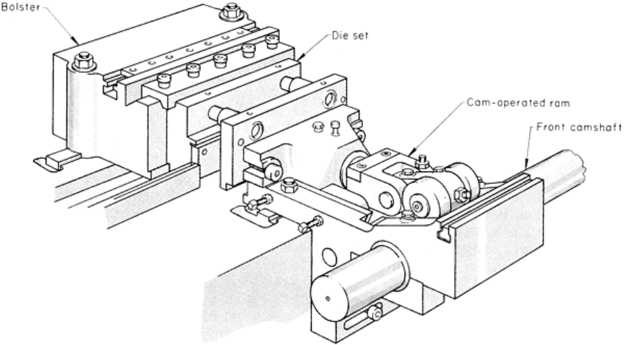
Fig. 2 Press station of a multiple-slide forming machine. See text for details.
Stock straighteners used on multiple-slide machines are similar to those described in the article "Presses and
Auxiliary Equipment for Forming of Sheet Metal" in this Volume. The primary difference is that in a multiple-slide
machine the rolls are mounted vertically to straighten the work metal as it passes through the machine on edge, instead of
horizontally as in a conventional press.
The stock-feed mechanism of a multiple-slide machine is made of two separate units constituting the forward
gripping and transporting device (M, Fig. 1) and a stationary gripping unit (P) to hold the strip when it is released on the
return stroke of the feed. The stock-feed slide is reciprocated through a system of links from a crank disk keyed to the
left-hand camshaft of the machine (M, O, and C, Fig. 1).
Press Station. The die used for piercing, trimming, embossing, and minor forming of the stock is mounted in the press
station, which consists essentially of a horizontal press operated by a cam on the front shaft (Q and D, Fig. 1). It may
consist of a single unit, as shown in Fig. 2, or additional units can be placed side by side, especially in the larger
machines.
Die head units can also be operated from front, rear, or both in machines that are constructed symmetrically. Burr
direction can be controlled at designer option.
Cams provide a positive movement to the press slide in both directions, so that the tools are withdrawn from the strip at
the end of the working stroke. A dwell at completion of the in-stroke provides time for opposing motions. This permits
working cleanly from each side of the stock. A means of adjusting the shut height of the die is provided. The entire unit
can also be moved longitudinally along the bedplate to the desired position established by the feed length.
A bolster provides support for the die shoe, and a cam-actuated ram provides support and motion for the punch holder.
The cutoff unit, placed between the press and the front forming slide, is used for cutting work metal into blanks before
they are bent to shape. The ends can be cut off straight, or the cut can be curved.
The cutoff unit consists basically of a horizontal slide that is operated through a lever from a cam on the front shaft. The
unit can be adjusted along the bedplate in order to cut off the blank at the required distance from the center post. A
positive cam action returns the slide so that the cutoff tool will not interfere with forming. Generally, the cutting die and
stripper, through which the work metal is fed, are stationary, while the punch moves to cut off the blank.
It is sometimes desirable to install a second cutoff unit on the right-hand side of the center post. The two units trim the
two ends of the blank to an accurate length. Because both ends of the blank are trimmed, slightly more stock is required
when this method is used, but the inaccuracies of a long feed length are corrected.
The forming station consists of four slides, a center post, and a stripper mechanism. Shaped tools in the four slides
progressively bend the workpiece around the center post. In most applications, the center post controls the shape of the
workpiece. The first forming tool, usually on the front slide, holds the blank against the center post during cutoff.
Each of the four forming slides runs in its own slideway machined in the bedplate, and each slide is operated positively in
both directions by cams. The front, rear, and right-hand slides are all similar in design; the left-hand slide is different
because it must pass underneath the press unit.
The tool holder and slide have a mating key and keyway machined parallel to the slide motion so that the forming tool
can be adjusted in this direction. A keyway in the top of the tool holder at right angles to the slide movement and a mating
key on the end of the forming tool allow sidewise adjustment. The cam that operates each forming slide is made in two
halves and has radially disposed slots so that it can be easily exchanged or timing can be adjusted.
The unit shown in Fig. 3 holds the center post rigidly in position for the forming tools to operate around and provides the
means for stripping the completed parts off the center post. The center post is fitted and rigidly secured to a king post,
which generally consists of a square or rectangular steel bar. The king post fits into a recess in an overhead horizontal
slide and is clamped in position by a steel plate and screws. This arrangement holds the king post and center tool rigid and
allows for easy adjustment of the vertical position of the center post. The center tool is held square with the forming tools
at all times.
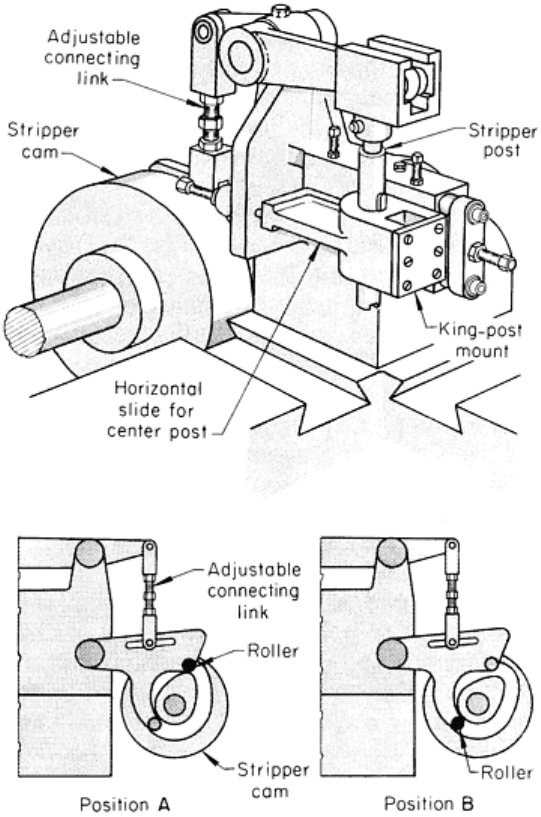
Fig. 3 Unit containing cam-
operated stripping mechanism and horizontal slide for mounting of the center post
assembly. See text for details.
The overhead slide, carrying the center post, moves parallel with the front and rear slides and is pushed backward by the
action of the front tool holding the strip against the center post until the slide reaches a stop, when the metal is bent to
shape. When the front tool retracts, the slide containing the center post is returned by spring pressure until a stop is
reached. If desired, the slide can be held in a fixed position by adjustment of the two stops. The sliding center post
arrangement minimizes interference between the cutoff die and the left-hand slide tools.
Workpieces are ejected from the center post by the downward movement of a suitably shaped stripper plate. The stripper
plate is held on a vertical rod, which derives its motion through a system of levers from a positive-action cam on the rear
shaft. During forming, the stripper plate is positioned above the forming tools. The vertical rod is guided by a bushing in
the overhead slide.
The stripper-cam lever has provision for the roller to be in one of two positions. With the roller as shown in position A,
Fig. 3, the cam acts as a normal ejector, moving quickly down and returning the stripper rod almost immediately. With
the roller in position B, the rod is held down for a longer period and remains in the upward position only for a short time.
This arrangement is used when a retractable mandrel is attached to the mechanism in place of a stripper plate. The
mandrel can be held down for a long time while the forming takes place and can then be quickly retracted, as may be
required in a further forming or closing operation.
Forming of Steel Strip in Multiple-Slide Machines
Revised by Deborah A. Blaisdell, The U.S. Baird Corporation
Blanking
The blank that is bent to shape in the forming station has all of the prior operations done in the press station. Trimming
the blank outline; piercing holes; embossing ribs, weld projections, and hole flanges; and stamping letters and numerals
are done before the blank is cut off and formed. The blank is severed from the strip by cutting off, parting, or blanking
methods.
Dies used in multiple-slide machines are either single-stage or progressive, depending on the complexity of the part
being formed. Generally, a progressive die is used, even though it may be only a simple two-station pierce-and-pilot die.
The dies for producing the blank must be made as accurately for a multiple-slide machine as they are for a conventional
press. However, the multiple-slide dies are of a simpler design and are less expensive than conventional press dies
because most of the forming is done in a separate station and around the center post.
The strip layout and die construction are similar to those for progressive dies used in conventional presses. However, as
noted previously in this article, the bending operations are usually done in the forming station and cutting off is usually
done in the cutoff unit, unless a transfer unit is used to transport the blank from the press station to the forming station.
Air jets are used where possible to eject the pierced slugs from the die.
The forming of lanced detents and flanged holes toward the punch side of the blank can be done by actuating the punches
with cams on the rear camshaft. Additional movements of die units can be obtained from any of the three other camshafts.
Extended dies are progressive dies that are mounted in the press station and extend into the forming station. After the
usual piercing, notching, and piloting operations, bending or forming is done by a combination of elements in the
progressive die and those actuated by the front and rear camshafts. The stripper mechanism can be used to advance and
retract a mandrel around which the part is bent. The moving or positioning of punches and dies by the camshafts can
make it possible to use tools that are much simpler in design than those made for operations in conventional presses. The
parts made in extended dies are generally those that can be retained on the strip until all operations are complete before
the part is cut off.
Cutting off the blank is usually done with a blade and die mounted in the cutoff unit. The die is fixed to the housing
across which the strip of work metal passes. The blade is secured to the slide so that when it is given a forward
movement, the blank is sheared from the strip.
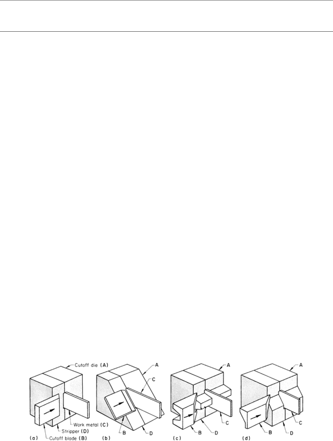
Basically, the cutoff tool consists of two flat pieces of metal: the cutoff die (A) and the blade (B), as shown in Fig. 4(a). A
fixed stripper (D) holds the work metal (C) against the die, and when the blade moves across the face of the die, the metal
is severed. Most of the parts illustrated in this article were cut from the strip by this method.
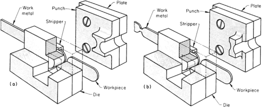
Fig. 4 Four arrangements of cutoff blades and dies for multiple-slide forming machines. See text for details.
The die and blade can be modified to give a shaped cut, as shown in Fig. 4(b) to (d). The shapes illustrated can be used
when forming ringlike parts that have a smooth-fitting joint.
Shaped ends on a workpiece can be formed by two methods. The first consists of cutting the full contour of the ends of
two adjacent parts in one machine stroke, as shown in Fig. 5(a). The second method consists of partly developing the
contour in the press station and then using the cutoff station to complete the contour by parting the blank from the strip by
shearing the connecting tab, as shown in Fig. 5(b).
Fig. 5 Tw
o types of parting dies used to shape the ends of blanks before forming. (a) Die for cutting the
contour in one stroke. (b) Die for completing the contour by parting a partially developed blank from the strip.
Blending of the parting punch with the previously cut contour may necessitate the use of a punch with sharp corners,
which could shorten punch life. If not properly blended, flats or other evidence of mismatch will appear on the severed
workpiece.
As shown in Fig. 5, the parting punch is mounted on the plate at the rear of the strip. The die is fitted with a stripper into
which the metal is guided across the front of the die. The die and the stripper are both mounted on the slide of the cutoff
unit and move horizontally toward the punch, carrying the strip metal with them. When the work metal contacts the
punch, the ends are sheared. The scrap is ejected through the die.
Normal press practice is for the die to remain stationary and the punch to move. This is reversed when parting in the
cutoff unit so that the end of the metal can swing clear, which would not be possible if the die were at the back of the
strip.
Another way in which shaped ends can be produced is to provide a cutoff unit at each side of the front forming tool, each
unit being fitted with a die to cut one end. When pilots cannot be used in the die or when a long blank is being cut, the
second unit helps in solving tooling problems.
Short Blanks. When the length of the blank is short and the end is very close to the forming slides, the cutoff blade can
be fastened to the front tool. The blade is fitted and secured to the front tool; an adjustment screw provides for positioning
of the blade. The cutoff die is positioned to mate with the blade.
Transfer of blanks from the cutoff unit to the forming station is generally unnecessary, because the blank can be
moved into the forming station before it is cut from the strip. However, it is sometimes desirable to cut the blank from the
strip at the last station in the progressive die, as in ordinary press blanking. In such a cycle, a transfer unit such as that
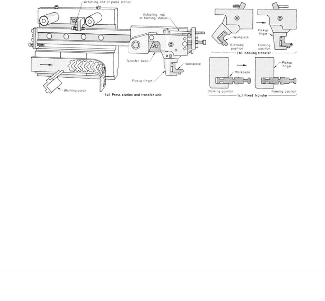
shown in Fig. 6(a) is used, which transfers the blank to the forming station. The transfer head is actuated by a stub shaft
located below the left-hand camshaft (C, Fig. 1).
Fig. 6
Mechanism for indexing and fixed transfer of blanks from the press station to the forming station of a
multiple-slide machine.
After the blanking punch has retracted, the blank is held in the die cavity. The blank is then pushed out of the die cavity
with a plunger that is moved forward by a cam fixed to the rear shaft and into the waiting pickup finger. The blank is
transported horizontally to the forming station, where the first forming tool pushes the blank out of the pickup finger and
against the center post. While the forming tools are bending the blank around the center post, the transfer head moves
back to the press station for another blank.
A blank can be picked up in the blanking station in one position and indexed to the forming position during the transfer
motion (Fig. 6b). This permits the strip layout to be designed for optimal stock use. Bends can also be positioned
favorably with respect to the rolling direction.
The transfer of blanks from the blanking position to the forming position without reorientation is shown in Fig. 6(c). The
pickup finger is mounted in the transfer head so that no swiveling or indexing takes place.
Timing of the transfer-head motion is important. The finger must be in position for loading or unloading, but must not
interfere with the blanking punch or the forming slides.
Forming of Steel Strip in Multiple-Slide Machines
Revised by Deborah A. Blaisdell, The U.S. Baird Corporation
Forming
As the work metal strip leaves the press station, it passes through the cutoff unit and between the center post and the first
forming tool (usually the front tool). Simultaneously with the cutting off of the blank, the front forming tool moves
forward and holds the blank firmly against the center post. By continued movement of the front tool, the blank is bent
around the center post. Tools on the two side slides move in to make further bends, and these can be followed by a fourth
tool on the rear slide to complete the forming. The sequence in which the slides move is not fixed, nor is it always
necessary to use all four slides when forming a part.
Holding blanks firmly in position against the center post is necessary while they are being severed from the stock and
also during the initial forming operation in order to prevent slipping and to ensure against premature bending or kinking
across a weak section. The work metal is likely to bulge when a U-shape part is being formed. Such a bulge is not
removed when the tools are fully closed, because the surplus metal cannot flow while the blank is held firmly by the two

corners of the bending tool. In some applications, a spring-loaded plunger in the first forming tool is positioned slightly in
advance of the bending portions and prevents the blank from bulging when the bends are started. A positive blankholder
is essential for holding forms having a weak section between the bends or for preventing slipping or dragging of a blank
around the corner when bending takes place. A partly formed blank also must be held while being moved to the lower
level and until a form tool can grip it.
There are two general types of mechanically operated blankholders. One type makes use of the standard stripping
mechanism, and the other is operated by a cam and lever from one of the shafts.
Part Ejection. After all tools are retracted, the formed part is ready for ejection by the stripper plate. During forming,
the stripper plate is positioned at the top and clear of the forming tools. After forming, the stripper plate moves down and
ejects the part from the center post. The stripper can also move a partly formed component into a second, or even a third,
forming level on the center post.
Multiple-Part Forming. Forming of more than one part per cycle of the machine should be considered when planning
the tools for production, but the increased loading must be within the capacity of the equipment. The way in which the
outline of the part is developed depends largely on its finished shape. If a part can be made of strip stock by piercing,
cutting off, and forming, then more than one part can be made in each cycle by slitting the strip into two or more ribbons.
For parts having shaped ends (for example, semicircular), the strip can be slotted and the blank then cut off. Slotting the
strip may eliminate the need for sharp corners on the punch and die, thus increasing their service lives. Parts with more
complex outlines require more complex trimming punches. The blank is severed from the strip by either cutoff or parting
methods.
Some parts, such as those having the basic shape of an L, are easier to form into a U-shape and then part after forming.
The bottom forming level of a multiple-slide machine can be used for parting. The parting punch is positioned on the rear
tool slide, and the die on the front tool. The center post has a clearance hole for the punch.
Forming Level. Forming can be done around the center post at the same level at which the blank enters the forming
station (single-level forming) or at one or two positions below that level (two- or three-level forming). Parts can be finish
formed at the lower level, resistance welded into ringlike parts, or finish formed and then cut into two or more pieces. The
partly completed workpieces are usually moved to the lower level by the stripper mechanism.
Single-level forming is used when all of the bends can be made with one set of forming tools, usually with one forward
stroke per machine cycle. Sometimes, a bend can be made by partly forming, retracting the tool, doing some work by
another tool, and then advancing the first tool to finish the bend. Auxiliary forming tools actuated by separate cams or
lever arrangements can be used to do more work on a piece. Wide blanks are usually formed at one level because of the
length of center post needed to support more than one part and because of the limited space available mounting tools.
During two-level forming, two components are on the center post--one at the top level and the other at the bottom level.
Work is done simultaneously on each piece by the forming tools. Forming is often done at both levels simultaneously by
providing each slide with a tool that is shaped to perform an operation on each piece. The workpiece at the lower level is
pushed off of the center post by the downward movement of the partly completed piece from the top level.
One of the simplest applications of two-level forming is the manufacture of bushings and ferrules by forming the center
and the ends of the blank at the top level and finish forming to final diameter at the bottom level. A more complicated
application of two-level forming is described in the following example.
Example 1: Two-Level Forming of a Hose Clamp.
The hose clamp shown in Fig. 7 was made from cadmium-plated steel 9.5 mm ( in.) wide at two levels on the center
post in a multiple-slide machine. At the press station, the three holes were pierced and a score mark or slight kink was
formed between two holes to ensure that the two holes would coincide after the metal had been folded back on itself.
Pilots in the press station ensured accurate location of the strip for cutoff and forming. The forming tools used for the two
levels are shown at left in Fig. 7.
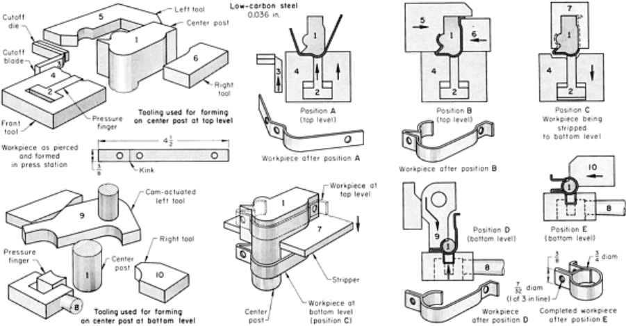
Fig. 7 Forming tools used and sequence of operation in the forming of a low-
carbon steel hose clamp.
Dimensions given in inches.
At position A in Fig. 7, the cutoff blade (3) sheared the blank from the strip while it was held against the center post (1)
by the pressure finger (2). The front tool (4) formed the blank as shown. The side tools (5 and 6) are shown pressing the
stock around the center post in position B. With the front and side tools retracted in position C, the pressure finger held
the formed part against the center post while the stripper (7) moved the part to the lower level, where the spring-loaded
lever arm and pressure finger (8) held the part.
In position D at the bottom level, the pivoting rear tool (9) formed the part around the center post (circular in shape at this
level). The rear tool also set the folded-over metal against an extension of the front tool (4). The final forming operation
by the right tool (10) was as shown in position E.
In the next cycle, the stripper pushed a new workpiece down to the bottom level, as the completed hose clamp was pushed
off of the center post. The cycle time was about 60 components per minute.
Lockseaming. Metal strip is used to make large quantities and varieties of small open-end boxes, tubes, and cylinders to
be used as ferrules for paint brushes, radio shields, and many other common products. All of these are made with some
locking method for joining the ends of the metal.
In lockseaming or can seaming, one end of the metal is formed over the other and flattened into a tight joint. Other
methods of locking two ends of metal together in multiple-slide machine include interlocking dovetails, raised tabs
inserted through slots and then flattened or twisted, a tongue inserted into a lanced slot and then swaged, and lancing and
forming through two stock thicknesses.
Lockseaming can be done at either one or two levels around the center post. Single-level forming is used where the tubes
are long or where projecting lugs would be too weak to push the finished part off of the center post. In this method, the
rear and side tools must be advanced two or three times during each cycle of the machine.
Two-level forming with an attachment that gives a positive movement to the seaming tools is a more efficient method of
making lockseams. The sliding head containing the center post can be used to make several sizes of lockseam tubes by
setting the rear and side tools a fixed distance from the strip line, then changing only the front tool and the center post.
The following example describes a two-level forming operation for external lockseaming to make a short cylindrical tube.
Example 2: Two-Level External Lockseaming to Produce a Round Tube.
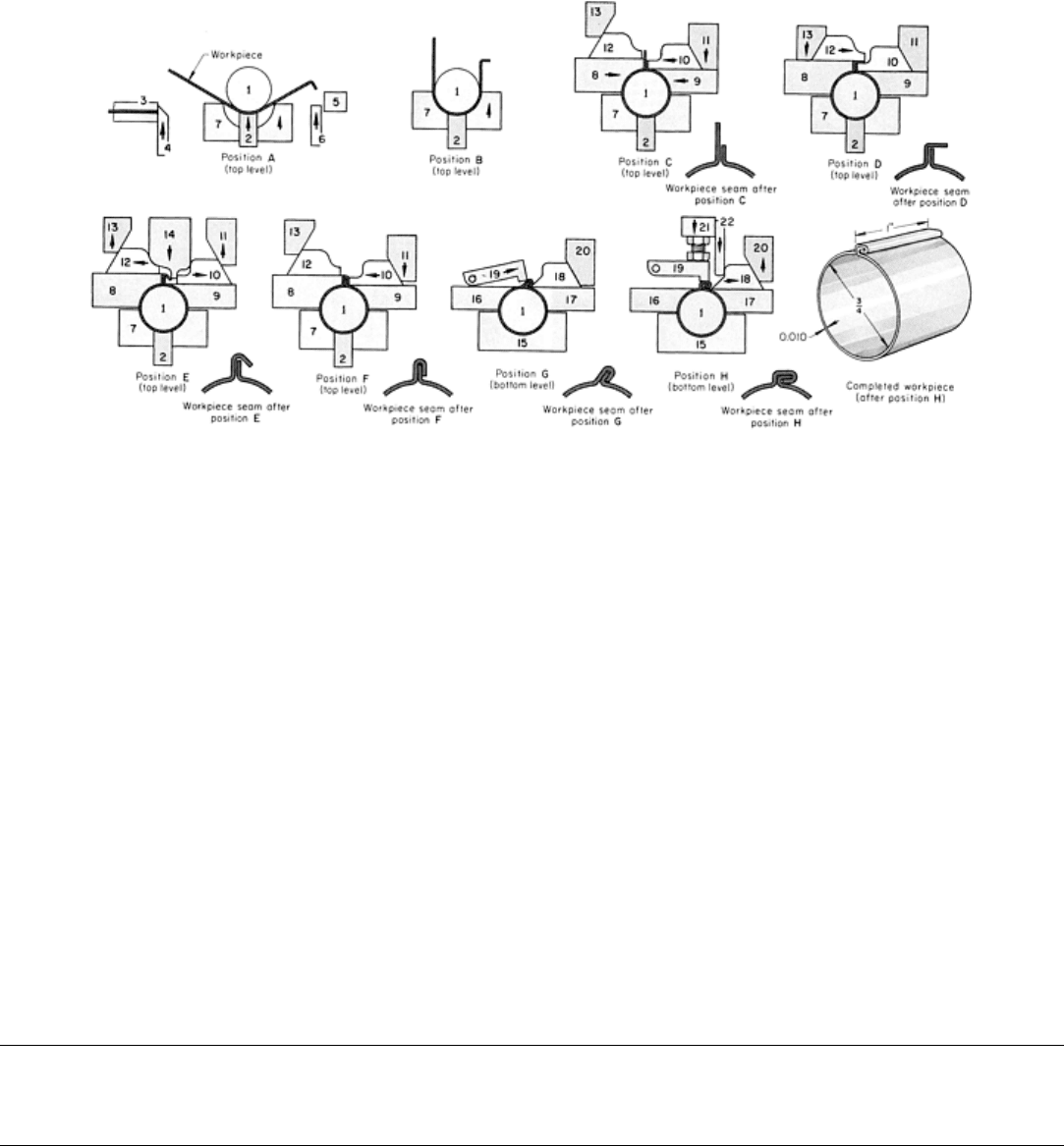
The external lockseam of the tube shown in Fig. 8 was formed at two levels in a multiple-slide machine. At position A,
the strip had been fed between the center post (1) and the pressure finger (2) and sheared by the cutoff die (3) and blade
(4). At the same time, the right-hand end of the blank had a small flange formed by the fixed tool (5) and the blade (6).
Position B shows the blank formed into a U-shape by the front tool (7). Forming of the cylinder by the side tools (8 and 9)
is shown in position C. The two ends extend at right angles to the surface, one end being longer than the other. The right
tool (10), moved by the cam (11), supported the previously bent flange as the left tool (8) formed the longer end. At
position D, the left tool (12), actuated by the cam (13), bent the long end over the shorter end.
Fig. 8 Two-level forming of an external lockseam to produce a cylindrical part. Dimensions given in inches.
At position E, the cams (11 and 13) retracted, allowing the side tools (10 and 12) to be pushed aside by the advancing rear
tool (14), thus permitting the end of the seam to be bent. The rear tool retracted, and the cam (11) advanced to move the
side tool (10) to flatten the seam against the left tool (8), as shown in position F. The part then was transferred to the
lower level by the stripper (not shown).
At the bottom level, the front tool (15) and the side tools (16 and 17) held the cylinder on the center post. The front tool
also backed up the center post during the final forming operations. As shown in position G, the anvil (18) supported the
seam while the swinging tool (19) moved forward to bend the seam at an angle. The anvil is moved by the cam (20). Final
flattening of the seam is shown in position H. As the rear tool (21) advanced, the cam projection (22) contacted the anvil,
pushing it clear as the swinging tool (19) closed the seam.
Two workpieces were on the center post at this stage, and both were formed at the same time. One, formed through
position F, was at the top level; the other was at the bottom level. Both were held tightly on the center post. The
completed piece was pushed off of the center post and into a container.
Internal lockseams can be made by forming an external seam, as shown in Fig. 8, and then re-forming the part to
make the seam flush with the outer surface. The part is moved to the lower level, where a vertical slot in the center post
provides space for the seam as it is pushed inward.
Forming of Steel Strip in Multiple-Slide Machines
Revised by Deborah A. Blaisdell, The U.S. Baird Corporation
Assembly Operations