ASM Metals HandBook Vol. 14 - Forming and Forging
Подождите немного. Документ загружается.

Dies
Dies used for drawing sheet metal are usually one of the following basic types or some modification of these types:
• Single-action dies
• Double-action dies
• Compound dies
• Progressive dies
• Multiple dies with transfer mechanism
Selection of the die depends largely on part size, severity of draw, and quantity of parts to be produced.
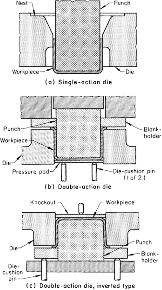
Single-action dies (Fig. 4a) are the simplest of all drawing dies and have only a punch and a die. A nest or locator is
provided to position the blank. The drawn part is pushed through the die and is stripped from the punch by the
counterbore in the bottom of the die. The rim of the cup expands slightly to make this possible. Single-action dies can be
used only when the forming limit permits cupping without the use of a blankholder.
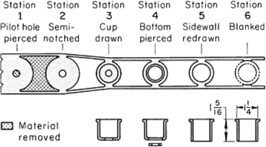
Fig. 4 Components of three types of simple dies shown in a setup used for drawing a round cup.
See text for
discussion.
Double-action dies have a blankholder. This permits greater reductions and the drawing of flanged parts. Figure 4(b)
shows a double-action die of the type used in a double-action press. In this design, the die is mounted on the lower shoe;
the punch is attached to the inner, or punch slide; and the blankholder is attached to the outer slide. The pressure pad is
used to hold the blank firmly against the punch nose during the drawing operation and to lift the drawn cup from the die.
If a die cushion is not available, springs or air or hydraulic cylinders can be used; however, they are less effective than a
die cushion, especially for deep draws.
Figure 4(c) shows an inverted type of double-action die, which is used in single-action presses. In this design, the punch is
mounted on the lower shoe; the die on the upper shoe. A die cushion can supply the blankholding force, or springs or air
or hydraulic cylinders are incorporated into the die to supply the necessary blankholding force. The drawn cup is removed
from the die on the upstroke of the ram, when the pinlike extension of the knockout strikes a stationary knockout bar
attached to the press frame.
Compound Dies. When the initial cost is warranted by production demands, it is practical to combine several
operations in a single die. Blanking and drawing are two operations commonly placed in compound dies. With compound
dies, workpieces can be produced several times as fast as by the simple dies shown in Fig. 4.
Progressive Dies. The initial cost and length of bed needed for progressive dies usually limit their application to
relatively small workpieces. Figure 5 shows a typical six-station progression for making small shell-like workpieces on a
mass-production basis. However, larger parts, such as liners for automobile headlights, have been drawn in progressive
dies.
Fig. 5 Production of a small ferrule in a six-station progressive die. Dimensions given in inches.
The total number of parts to be produced and the production rate often determine whether or not a progressive die will be
used when two or more operations are required. There are, however, some practical considerations that may rule against a
progressive die, regardless of quantity:
•
The workpiece must remain attached to the scrap skeleton until the final station, without hindering the
drawing operations
• Drawing operations must be completed before the final station is reached
• In deep drawing, it is sometimes difficult to move the workpiece to the next station
• If the draw is relatively deep, stripping is often a problem
• The length of press stroke must be more than twice the depth of draw
Assuming that a progressive die can be used to make acceptable drawn parts, cost per piece is usually the final
consideration. Progressive-die drawing is generally considered to be economical if savings in material and labor can pay
for the die in 1 year. Ordinarily, the savings achieved by the use of a progressive die results from decreased labor.
Multiple dies, in conjunction with transfer mechanisms, are often used instead of progressive dies for the mass
production of larger parts. Multiple dies and transfer mechanisms are practical for a wider range of workpiece sizes than
progressive dies are. Although the eyelet-type transfer method is the most widely used for making parts less than 25 mm
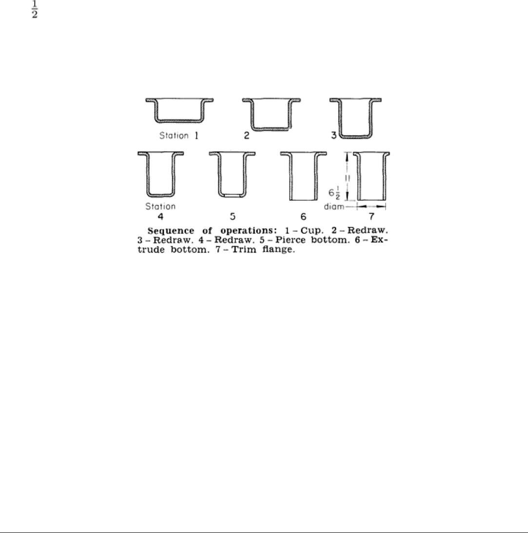
(1 in.) in diameter, transfer dies are practical for much larger workpieces. The seven-station operation for making the 165
mm (6 in.) outside diameter cylindrical shell shown in Fig. 6 represents a typical sequence for the transfer-die method.
The workpiece is mechanically transferred from one die to the next. One advantage of the transfer-die method, as opposed
to the progressive-die method, is the greater flexibility permitted in processing procedure, mainly because in transfer dies
the workpiece does not remain attached to the scrap skeleton during forming. Because of this, precut blanks can be drawn
by the transfer method.
Fig. 6 Seven-station drawing and piercing of a cylindrical part
in a multiple die and transfer mechanism.
Dimensions given in inches.
Preforms can also be used as blanks. For example, oil pans for automobiles are blanked and partly drawn in a compound
die, then finish formed, pierced, and trimmed by the transfer method.
Dies for producing a given part usually cost more for the transfer-die method than for a separate-die operation, but about
the same as for a progressive-die operation. The cost of adapting the transfer unit to the part is not included in the die cost.
Similarly, the production rate for the transfer method is usually greater than that for a single-die operation, but 10 to 25%
less than that for drawing in a progressive die. Many parts can be produced equally well by all of these methods. Under
these conditions, tool cost, rate of production, and total quantity of parts to be drawn determine the choice of procedure.
Die and Punch Materials. The selection of material for dies and punches for drawing sheet metal depends on work
metal composition, workpiece size, severity of the draw, quantity of parts to be drawn, and tolerances and surface finish
specified for the drawn workpieces. To meet the wide range of requirements, punch and die materials ranging from
polyester, epoxy, phenolic, or nylon resins to highly alloyed tool steels with nitrided surfaces, and even carbide, are used.
Detailed information on tool materials is available in the articles "Selection of Material for Press-Forming Dies" and
"Selection of Material for Deep-Drawing Dies" in this Volume.
Deep Drawing
Effects of Process Variables
The process parameters that affect the success or failure of a deep-drawing operation include punch and die radii, punch-
to-die clearance, press speed, lubrication, and type of restraint of metal flow used (if any). Material variables, such as
sheet thickness and anisotropy, also affect deep drawing. These are discussed in the section "Effects of Material
Variables" in this article.
Effect of Punch and Die Radii
As the blank is struck by the punch at the start of drawing, it is wrapped around the punch and die radii; the stress and
strain that develop in the workpiece are similar to those developed in bending, with an added stretching component. The
bends, once formed, have the radii of the punch and die corners. The bend over the punch is stationary with reference to
both punch and shell wall. The bend over the die radius, however, is continuously displaced with reference to both the
punch radius and the blank, and it also undergoes a gradual thickening as the shell is drawn. The force required to draw
the shell at the intermediate position has a minimum of three components:
• The force required for bending and unbending the metal flowing from the flange into the sidewall
• The force required for overcoming the frictional resistance of the metal passing under the blan
kholder
and over the die radius
• The force required for circumferential compression and radial stretching of the metal in the flange
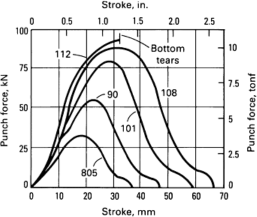
Because of the variation in metal volume and in resistance to metal flow, the punch force increases rapidly, passes
through a maximum, and gradually decreases to zero as the edges of the flange approach and enter the die opening and
pass into the shell wall. With the cup diameter remaining constant, the maximum press load and the length of stroke
required to draw the cup depend on the size of the blank. The punch force-stroke relations for drawing blanks of various
diameters from brass sheet 1.5 mm (0.060 in.) thick, using a 50 mm (2 in.) diam punch, are shown in Fig. 7.
Fig. 7 Force-stroke relations for drawing bl
anks of various diameters from 1.5 mm (0.060 in.) thick alloy
C27400 (yellow brass, 63%) sheet using a 50 mm (2 in.) diam punch.
Numbers indicate blank diameter in
millimeters.
Under the conditions shown in Fig. 7, during cupping, the shell bottom is subjected to tensile stress in all directions, while
the lower portions of the shell wall, particularly the radiused portion connecting the bottom with the wall, are primarily
subjected to longitudinal tension. The stress in the metal being drawn into the shell wall consists of combined
compressive and tensile stresses. Separation of the shell bottom from the wall is likely if a reduction is made that requires
a force greater than the strength of the shell wall near the bottom (Fig. 7).
The punch and die radii and percentage of reduction determine the load at which the bottom of the shell is torn out.
Drawing is promoted by increasing punch and die radii. For a given drawing condition, the punch force needed to move
the metal into the die decreases as the die radius increases, as shown in Fig. 8.
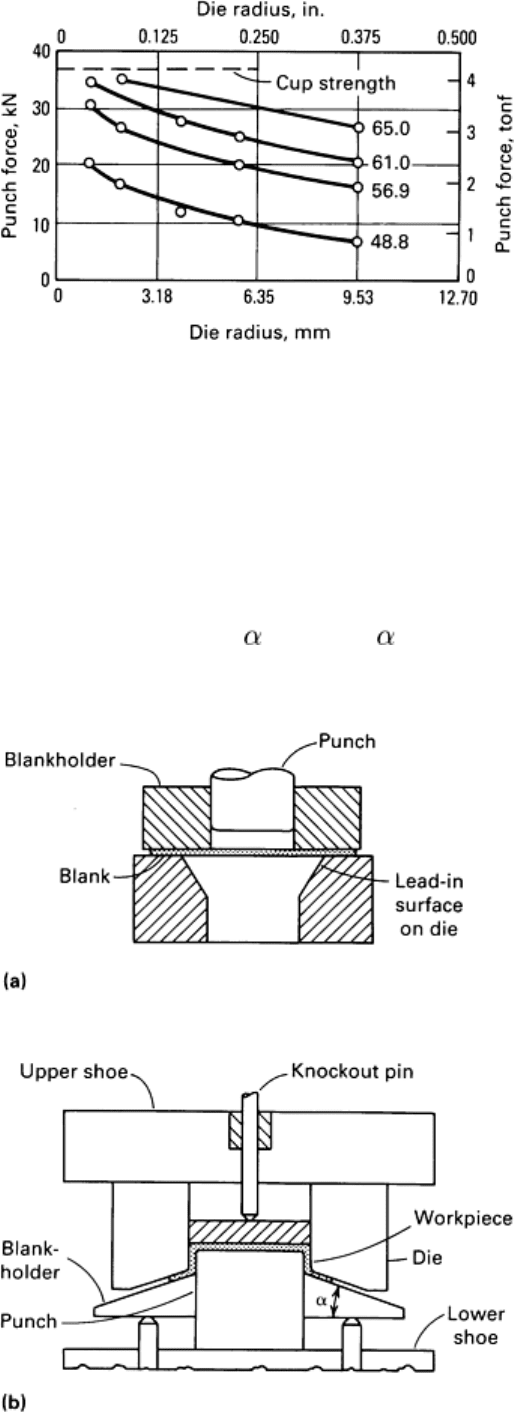
Fig. 8
Effect of die radius on punch force required for cupping various diameters of 1 mm (0.040 in.) thick alloy
C27400 (yellow brass, 63%) blanks using a 30.5 mm (1.2 in.) diam punch with
a nose radius of 0.61 mm
(0.024 in.). Numbers indicate blank diameter in millimeters.
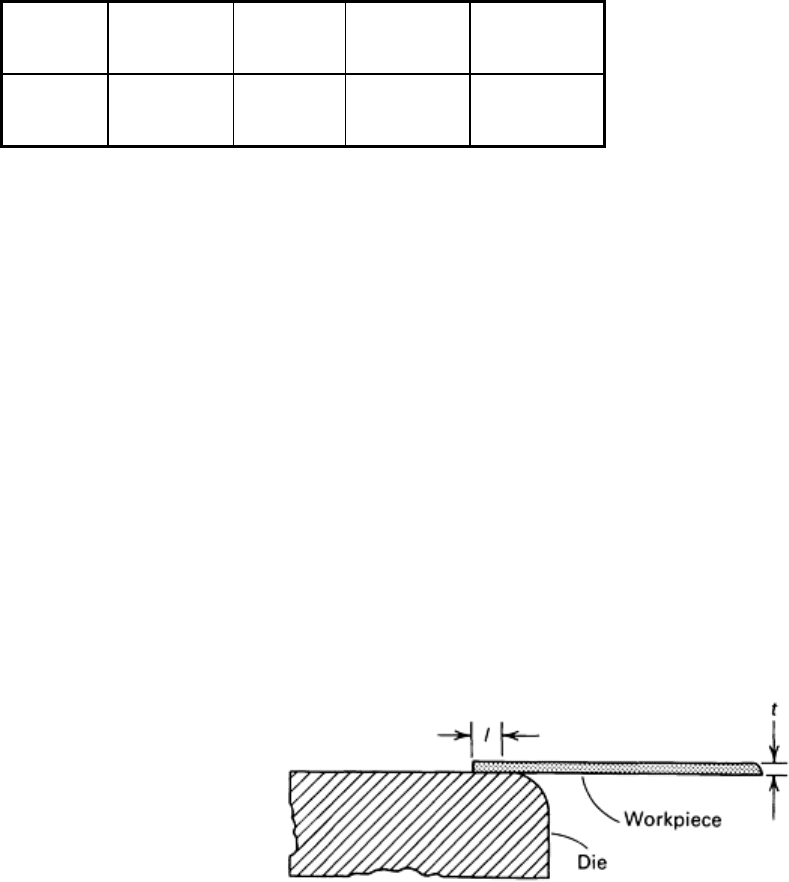
The reduction of drawing force in a double-action die by modification of the effective die radius can be accomplished in
two convenient ways, as shown in Fig. 9. In the conical lead-in die (Fig. 9a), the cutout is effective in reducing frictional
loads by removal of the portions of the die surface that are usually heavily loaded and increase friction. In Fig. 9(b), the
sheet metal is formed into a conical shape before appreciable drawing begins. This has the effect of reducing the area of
contact over the die radius by an amount proportional to /90° (where is the angle to declination of the hold-down
surface to the horizontal, as shown in Fig. 9b).

Fig. 9 Two ways of reducing the required drawing forces. (a) Conical lead-in die.
(b) Conical blankholder. See
text for details.
If the punch nose radius can be increased from one to five times metal thickness, the load in the sidewall of the shell will
decrease so that the reduction in blank diameter will increase from 35% to about 50% (for steel). The shell can therefore
be drawn deeper before the sidewall tears.
If the shell bottom radius is less than four times the sheet thickness, it is usually desirable to form it with a larger-radius
punch and then to restrike to develop the specified radius. This will minimize bottom failures. However, the bottom
corner radius usually cannot be increased beyond ten times the sheet thickness without the likelihood of wrinkling. The
metal in dome-shaped parts is likely to pucker in the unconfined area between the punch nose and die radius. High
blankholding forces or draw beads are often used to induce combined stretching and drawing of the metal when forming
dome shapes.
The deep drawing of stainless steel or high-strength alloy boxes with sides longer than 50 times stock thickness may
result in a stability problem called oil canning. The deflection of the sides by snap action can be eliminated by drawing
the part in two operations with slightly different punches and an intermediate anneal. The first-draw punch will have a
larger nose radius than the second; therefore, in the second drawing operation, the metal can be stretched to eliminate the
oil-canning effect. Stretching of the metal in parts with long sidewalls can be improved by gradually increasing the punch
nose radius from the corner toward the center. A constant nose radius is used on the second-draw punch.
Effect of Punch-to-Die Clearance
The selection of punch-to-die clearance depends on the requirements of the drawn part and on the work metal. Because
there is a decrease and then a gradual increase in the thickness of the metal as it is drawn over the die radius, clearance per
side of 7 to 15% greater than stock thickness (1.07 to 1.15t) helps prevent burnishing of the sidewall and punching out of
the cup bottom.
The drawing force is minimal when the clearance per side is 15 to 20% greater than stock thickness (1.15 to 1.20t) and the
cupped portions of the part are not in contact with the walls of the punch and die. The force increases as the clearance
decreases, and a secondary peak occurs on the force-stroke curve where the metal thickness is slightly greater than the
clearance and where ironing starts.
Redrawing operations require greater clearance, in relation to blank thickness, than the first draw in order to compensate
for the increase in metal thickness during cupping. A sizing redraw is used where the diameter or wall thickness is
important or where it is necessary to improve surface finish to reduce finishing costs. The clearance used is less than that
for the first draw.
Table 1 lists clearances for cupping, redrawing, and sizing draws of cylindrical parts from metal of various thicknesses.
As the tensile strength of the stock decreases, the clearance must be increased.
Table 1 Punch-to-die clearance for drawing operations
Metal thickness, t
Clearance-to-metal-thickness relationship for:
mm in. Cupping Redrawing
Sizing draws
Up to 0.38 Up to 0.015 1.07-1.09t 1.08-1.10t
1.04-1.05t
0.41-1.27 0.016-0.050 1.08-1.10t 1.09-1.12t
1.05-1.06t
1.29-3.18 0.051-0.125 1.10-1.12t 1.12-1.14t
1.07-1.09t
3.2 and up
0.126 and up
1.12-1.14t 1.15-1.20t 1.08-1.10t
Clearance between the punch and die for a rectangular shell, at the sidewalls and ends, is about the same as, or slightly
less than, that for a circular shell. Clearance at the corners may be as much as 50% greater than stock thickness to avoid
ironing in these areas and to increase drawability.
Restraint of Metal Flow
Even in the simplest drawing operation, as shown in Fig. 4(a), the thickness of the work metal and the die radius offer
some restraint to the flow of metal into the die. For drawing all but the simplest of shapes, some added restraint is
generally required in order to control the flow of metal. This additional restraint is usually obtained by the use of a
blankholder, as illustrated in Fig. 4(b) and 4(c). The purpose of the blank-holder is to suppress wrinkling and puckering
and to control the flow of the work metal into the die.
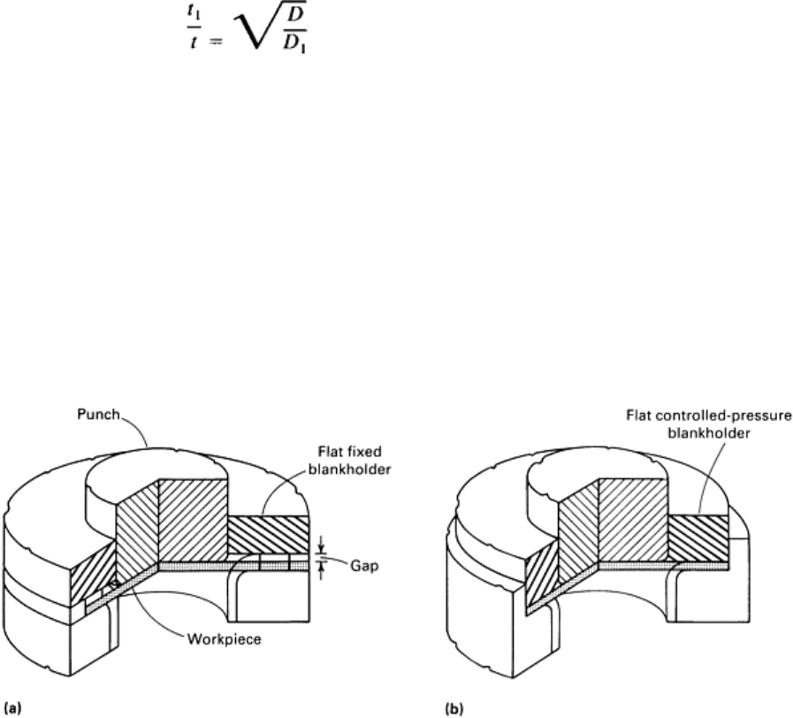
Drawing Without a Blankholder. A blank is not susceptible to wrinkling, and a blankholder need not be used, if the
ratio of supported length to sheet thickness is within certain limits. In Fig. 10, the supported length l is the length from the
edge of the blank to the die cavity (point of tangency). The sheet thickness is denoted as t. The l/t ratio is influenced little
by other geometrical conditions, and it differs little for the various metals commonly drawn. When the l/t ratio does not
exceed 3 to 1, a cup can be drawn from annealed brass, aluminum (to half-hard), and low-carbon steel without a
blankholder. For slightly harder work metals, such as hard copper or half-hard brass, this ratio should not exceed 2.5 to 1.
Fig. 10 The ratio of supported length l to sheet thickness t
determines whether or not a blankholder is required
for deep drawing.
An elliptical or conical die opening, such as that shown in Fig. 9(a), can be used where the die radius required to draw the
part reduces the length of the blank-supporting surface to less than three times stock thickness. The distance between the
die opening and the punch should not exceed ten times stock thickness.
A 30° elliptical radius derived from a circle created by a given draw radius increases the strain on the metal being drawn
by 4.2%, but it decreases the metal out of control by 47% of the length of the original draw radius. This shape has been
helpful in the drawing of tapered shells from a flat blank. For these draws, it is desirable to increase the strain slightly to
prevent puckers and to reduce the metal out of control for the same reason.
A 45° elliptical radius derived as above reduces the strain on the metal being drawn by 1.03% and reduces the metal out
of control by 33% of the length of the original draw radius. The 45° ellipse is useful only when a large radius will draw
the part, but produces wrinkles. A smaller radius will not permit the draw.
A 60° elliptical radius does not measurably reduce drawing strain and accounts for only a 9% reduction of metal out of
control. Its use on draw dies is not economically feasible when the small gains derived are considered in relation to the
cost of producing the contour. The drawing of thick metal without a blankholder is frequently done when the blank
diameter is no greater than 20 times stock thickness.
Blankholders. The purpose of a blankholder is to prevent wrinkles from forming in the flange of a part during drawing.
The formation of wrinkles interferes with, or prevents, the compressive action that rear-ranges the metal from flange to
sidewall. Much greater reductions are possible when a blankholder is used.
Blankholders can be used in double- and single-action presses. In a double-action press, the blankholder advances slightly
ahead of the punch and dwells at the bottom of its stroke throughout the drawing phase of the punch cycle. The
blankholder dwell usually extends to a point on the punch upstroke at which positive stripping of the shell is ensured. By
using a die cushion and an inverted die, similar action can be obtained in a single-action press. A die cushion in a double-
action press supports the blank and holds it against the punch during the drawing operation; it then lifts the finished part
out of the die.
A blankholder must allow the work metal to thicken as the edge of the blank moves inward toward the working edge of
the die. The amount of thickening is expressed by:
(Eq 8)
where t is the blank thickness, t
1
is the thickness of the flange at any instant during the drawing operation, D is the blank
diameter, and D
1
is the diameter of the flange at any instant during the drawing operation (or the mean diameter of the
workpiece without the flange). As the metal flows, paths of least resistance are taken; therefore, the actual value of t
1
, will
be less than that calculated from the formula.
Types of Blankholders. The simplest type of blankholder is fixed to the die block and has a flat hold-down surface, as
shown in Fig. 11(a). A disadvantage of this type of blankholder is that maintenance of the optimal gap between the die
surface and the flat hold-down surface requires careful adjustment. As shown in Fig. 11, the blankholder does not quite
contact the work metal as drawing begins; restraint begins and increases as the flange portion thickens. A gap that is
either too small or too large increases force and reduces drawability. For optimal results, the gap should be slightly
smaller than the flange thickness, allowing 50 to 75% of the final thickening before the work metal contacts the
blankholder.
Fig. 11 Setups showing the use of two types of blankholders. See text for details.
The flat controlled-pressure blankholder shown in Fig. 11(b) is generally preferred in production operations because it can
be adjusted to a predetermined and closely controlled value by hydraulic or pneumatic pressure. Springs, unless extremely
long, are not suitable for supplying pressure to a blankholder during deep drawing, because the force exerted by a spring
increases rapidly as it is compressed. The force on hydraulic or pneumatic die cushions will increase about 20% when
compressed the full stroke length. Some hydraulic systems have pressure control valves that supply a more nearly
constant pressure during the entire stroke.
The fixed-type blankholder (Fig. 11a) draws a cup without a flange and ejects it through the bottom of the die. The
blankholder shown in Fig. 4(b) and 4(c) and in Fig. 11(b) can be used for drawing a cup with or without a flange. Cups
without a flange can be pushed through the die if a pressure pad is not needed to support the blank.
Blankholder Force. Compressive forces on the metal in the area beyond the edge of the die cause the work metal to
buckle. If this buckled or wrinkled metal is pulled into the die during the drawing operation, it will increase the strain in
the area of the punch nose to the point at which the work metal would fracture soon after the beginning of the draw.
Blankholder force is used to prevent this buckling and subsequent failure. The amount of blankholder force required is
usually about one-third that required for drawing. Thickness of the work metal must also be considered when simple
shapes are being drawn; the thinner the work metal, the more blankholder force that is required.
There are no absolute rules for calculating blankholder force for a given drawing operation; most blankholder force values
are found empirically. Blankholder force should be just sufficient to prevent wrinkling, and it depends on draw reduction,
work metal thickness and properties, the type of lubrication used, and other factors. For a particular application,
blankholder force is best determined experimentally.
Draw beads help prevent wrinkles and control the flow of metal in the drawing of shells. The use of draw beads
increases the cost of tools, product development, and tool maintenance. However, they are often the only means of
controlling metal flow in the drawing of odd shapes. Draw beads are ordinarily used for the first draw only; therefore,
production rates are the same as when conventional blankholders are used. For low production, draw beads are often
made by laying a weld bead on the die after the optimal location has been determined.
Restraint of the metal flow, to the extreme of locking the flange of the blank to prevent motion, is needed for some draws.
A deep shell with sloping walls can be made by drawing, followed by several redraws. This results in a stepped
workpiece. The final sizing draw is a stretching operation that is done with the flange secured by a locking bead in the
blankholder. This kind of blankholder is also used in making shallow drawn panels. Additional information on the design
and use of draw beads is available in the article "Press Forming of Low-Carbon Steel" in this Volume.
Effect of Press Speed
Drawing speed is usually expressed in meters per minute (m/min) or linear feet per minute (ft/min). Under ideal
conditions, press speeds as high as 23 m/min (75 ft/min) are used for the deep drawing of low-carbon steel. However, 6 to
17 m/min (20 to 55 ft/min) is the usual range--up to 17 m/min (55 ft/min) for single-action presses and 11 to 15 m/min
(35 to 50 ft/min) for double-action presses. Ideal conditions include:
• Use of a drawing-quality work metal
• Symmetrical workpieces of relatively mild severity
• Adequate lubrication
• Precision carbide tools
• Carefully controlled blankholding pressure
• Presses that are maintained to a high level of accuracy
When one or more of the above conditions is less than ideal, some reduction in press speed is required. If all, or nearly all,
are substantially less than ideal, press speed may have to be reduced to 6 m/min (20 ft/min). When the operation includes
ironing, the drawing speed is usually reduced to about 7.6 m/min (25 ft/min) regardless of other factors.
The punch speed in hydraulic presses is relatively constant throughout the stroke. In mechanical presses, punch speed is
that at mid-stroke because the velocity changes in a characteristic manner throughout the drawing stroke from maximum
velocity to zero. The only adjustment in speed that can be made is to decrease flywheel speed or to use a press with a
shorter stroke that operates at the same number of strokes per minute. This proportionately decreases maximum punch
speed.
Speed is of greater significance in drawing stainless steels and heat-resistant alloys than in drawing softer, more ductile
metals. Excessive press speeds have caused cracking and excessive wall thinning in drawing these stronger, less ductile
metals. Nominal speeds for drawing various metals are given in Table 2.
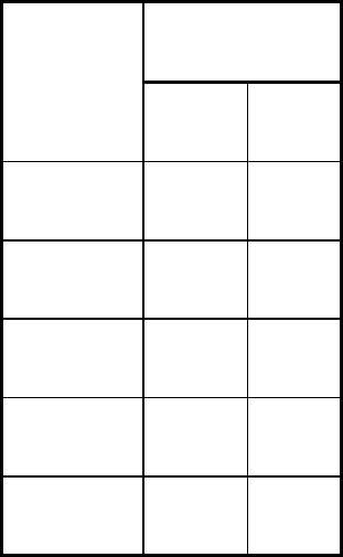
Table 2 Typical drawing speeds for various materials
Drawing speed
Material
m/min
ft/min
Aluminum 45.7-53.3
150-175
Brass 53.3-61
175-200
Copper 38.1-45.7
125-150
Steel 5.5-15.2
18-50
Stainless steel
9.2-12.2
30-40
Effect of Lubrication
When two metals are in sliding contact under pressure, as with the dies and the work metal in drawing, galling (pressure
welding) of the tools and the work metal is likely. When extreme galling occurs, drawing force increases and becomes
unevenly distributed, causing fracture of the workpiece.
The likelihood of pressure welding depends on the amount of force and the work metal composition. Some work metals
are more "sticky" than others. For example, austenitic stainless steel is more likely to adhere to steel tools than low-
carbon steel is.
Lubricants are used in most drawing operations. They range from ordinary machine oil to pigmented compounds.
Selection of lubricant is primarily based on the ability to prevent galling, wrinkling, or tearing during deep drawing.
It is also influenced by ease of application and removal, corrosivity, and other factors, as described in the article
"Selection and Use of Lubricants in Forming of Sheet Metal" in this Volume.
If a lubricant cannot be applied uniformly by ordinary shop methods, its purpose is defeated, regardless of its ability to
prevent pressure welding. In general, as the effectiveness of a lubricant increases, the difficulty of removing it also
increases. For example, grease or oil can be easily removed, but special procedures (frequently including some hand
scrubbing) are required for removing lubricants that contain zinc oxide, lithopone, white lead, molybdenum disulfide, or
graphite.
A lubricant is sometimes too corrosive for use on certain metals. For example, copper alloys are susceptible to staining by
lubricants that contain large amounts of sulfur or chlorine compounds. Lubricants containing lead or zinc compounds are
not recommended for drawing stainless steel or heat-resistant alloys, because the compounds, if not thoroughly removed,
can cause intergranular attack when the work-pieces are heat treated or placed in high-temperature service. Suitable safety
precautions are necessary with toxic or flammable lubricants.
Some metals, such as magnesium and titanium, are drawn at elevated temperature, which complicates selection of the
lubricant. Most oil-base and soap-base lubricants can be successfully used to 120 °C (250 °F), but above this temperature,
the choice narrows rapidly. Some special soap-base lubricants can be used on work metals to 230 °C (450 °F).
Molybdenum disulfide and graphite can be used at higher temperatures.