Askeland D.R., Fulay P.P. Essentials of Materials Science & Engineering
Подождите немного. Документ загружается.


describe isothermal heat treatments (i.e., we assume that the sample begins and completes
heat treatment at a given temperature). Thus, we cannot exactly describe heat treat-
ments by superimposing cooling curves on a TTT diagram such as those shown in
Figure 13-6.
Effect of Changes in Carbon Concentration on the TTT Diagram In either a hypo-
eutectoid or a hypereutectoid steel, the TTT diagram must reflect the possible formation
of a primary phase. The isothermal transformation diagrams for a 1050 and a 10110
steel are shown in Figure 13-7. The most remarkable change is the presence of a ‘‘wing’’
which begins at the nose of the curve and becomes asymptotic to the A
3
or A
cm
tem-
perature. The wing represents the ferrite start (F
s
) time in hypoeutectoid steels or the
cementite start (C
s
) time in hypereutectoid steels.
When a 1050 steel is austenitized, quenched, and held between the A
1
and the A
3
,
primary ferrite nucleates and grows. Eventually, an equilibrium amount of ferrite and
austenite result. Similarly, primary cementite nucleates and grows to its equilibrium
amount in a 10110 steel held between the A
cm
and A
1
temperatures.
If an austenitized 1050 steel is quenched to a temperature between the nose and
the A
1
temperatures, primary ferrite again nucleates and grows until reaching the equi-
librium amount. The remainder of the austenite then transforms to pearlite. A similar
situation, producing primary cementite and pearlite, is found for the hypereutectoid
steel.
If we quench the steel below the nose of the curve, only bainite forms, regardless of
the carbon content of the steel. If the steels are quenched to temperatures below the M
s
,
martensite will form. The following example shows how the phase diagram and TTT
diagram can guide development of the heat treatment of steels.
EXAMPLE 13-3
Design of a Heat Treatment for an Axle
A heat treatment is needed to produce a uniform microstructure and hardness
of HRC 23 in a 1050 steel axle.
SOLUTION
We might attempt this task in several ways. We could austenitize the steel, then
cool at an appropriate rate by annealing or normalizing to obtain the correct
hardness. By doing this, however, we find that the structure and hardness vary
from the surface to the center of the axle.
A better approach is to use an isothermal heat treatment. From Figure
13-7, we find that a hardness of HRC 23 is obtained by transforming austenite
to a mixture of ferrite and pearlite at 600
C. From Figure 13-1, we find that
the A
3
temperature is 770
C. Therefore, our heat treatment is:
1. Austenitize the steel at 770 þ (30 to 55) ¼ 805
C to 825
C, holding for
1 h and obtaining 100% g.
2. Quench the steel to 600
C and hold for a minimum of 10 s. Primary
ferrite begins to precipitate from the unstable austenite ðg
u
Þ after about 1.0 s.
After 1.5 s, pea rlite begins to grow, and the austenite is completely transformed
to ferrite and pearlite after about 10 s. After this treatment, the micro-
constituents present are:
C HA P T E R 1 3 Heat Treatment of Steels and Cast Irons400
Primary a ¼
ð0:77 0:5Þ
ð0:77 0:0218Þ
100 ¼ 36%
Pearlite ¼
ð0:5 0:0218Þ
ð0:77 0:0218Þ
100 ¼ 64%
3. Cool in air to room temperature, preserving the equil ibrium amounts
of primar y ferrite and pearlite. The microstructure and hardness are uniform
because of the isothermal anneal.
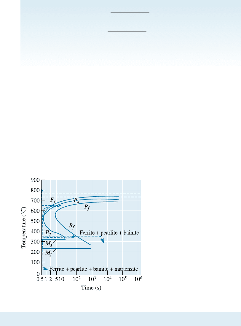
Interrupting the Isothermal Transformation Complicated microstructures are pro-
duced by interrupting the isothermal heat treatment. For example, we could austenitize
the 1050 steel (Figure 13-8) at 800
C, quench to 650
C and hold for 10 s (permitting
some ferrite and pearlite to form), then quench to 350
C and hold for 1 h (3600 s).
Whatever unstable austenite remained before quenching to 350
C transforms to bainite.
The final structure is ferrite, pearlite, and bainite. We could complicate the treatment
further by interrupting the treatment at 350
C after 1 min (60 s) and quenching. Any
austenite remaining after 1 min at 350
C forms martensite. The final structure now
contains ferrite, pearlite, bainite, and martensite. Note that each time we change
the temperatur e, we start at zero time! In practice, temperatures can not be changed
instantaneously (i.e., we cannot go instantly from 800 to 650 or 650 to 350
C). This is
why it is better to use the continuous cooling transformation (CCT) diagrams.
13-4 Quench and Temper Heat Treatments
Quenching hardens most steels and tempering increases the toughness. This has been
known for perhaps thousands of years. For example, a series of such heat treatments
has been used for making Damascus steel and Japanese Samurai swords. We can obtain
an exceptionally fine dispersion of Fe
3
C and ferrite (known as tempered martensite) if
Figure 13-8
Producing complicated structures by
interrupting the isothermal heat
treatment of a 1050 steel.
13-4 Quench and Temper Heat Treatments 401
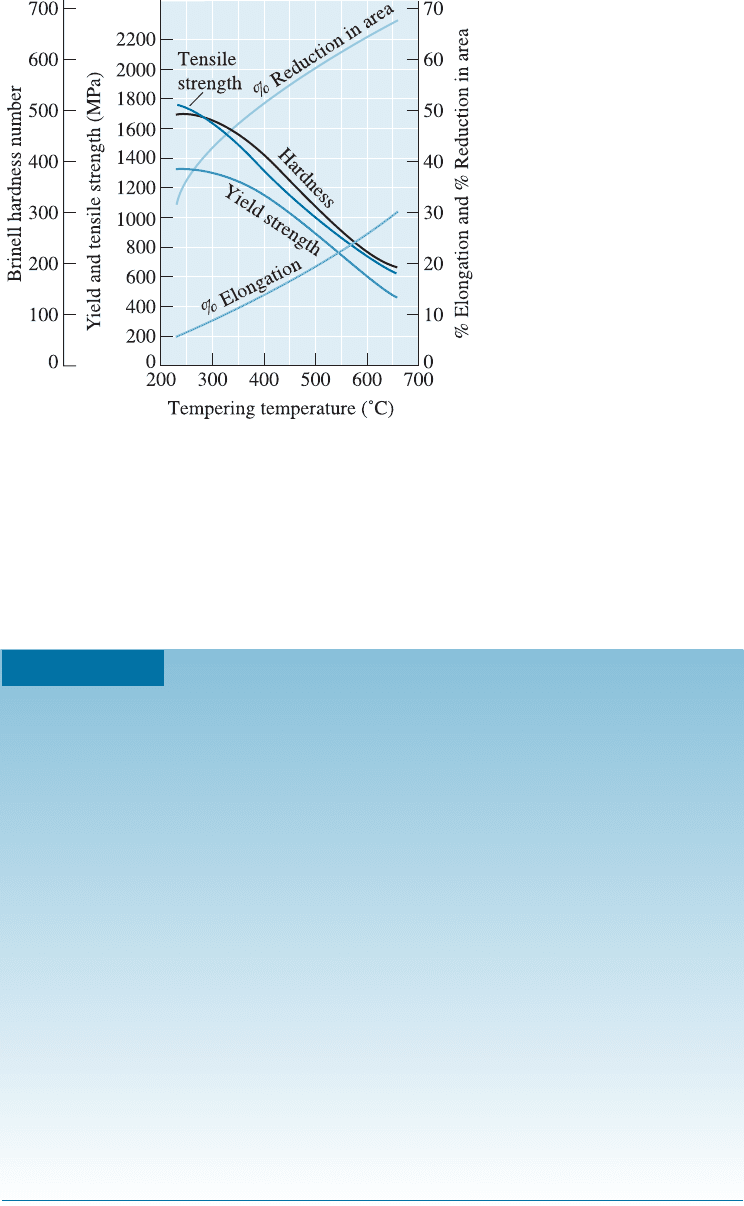
we first quench the austenite to produce martensite, then temper. During tempering, an
intimate mixture of ferrite and cementite forms from the martensite, as discussed in
Chapter 12. The tempering treatment controls the final properties of the steel (Figure
13-9). Note that this is di¤erent from a spheroidizing heat treatment (Figure 13-5). The
following example shows how a combination of heat treatments is used to obtain steels
with desired properties.
Figure 13-9
The effect of tempering
temperature on the mechanical
properties of a 1050 steel.
EXAMPLE 13-4
Design of a Quench and Temper Treatment
A rotating shaft that delivers power from an electric motor is made from a
1050 steel. Its yield strength should be at least 1000 MPa, yet it should also
have at least 15% elongation in order to provide toughness. Design a heat
treatment to produce this part.
SOLUTION
We are not able to obtain this combination of properties by annealing or nor-
malizing (Figure 13-4). However a quench and temper heat treatment produces
a microstructure that can provide both strength and toughness. Figure 13-9
shows that the yield strength exceeds 1000 MPa if the steel is tempered below
460
C, whereas the elongation exceeds 15% if tempering is done above 425
C.
The A
3
temperature for the steel is 770
C. A possible heat treatment is:
1. Austenitize above the A
3
temperature of 770
C for 1 h. An appropriate
temperature may be 770 þ 55 ¼ 825
C.
2. Quench rapidly to room temperature. Since the M
f
is about 250
C, mar-
tensite will form.
3. Temper by heating the steel to 440
C. Normally, 1 h will be su‰cient if the
steel component is not too thick.
4. Cool to room temperature.
C HA P T E R 1 3 Heat Treatment of Steels and Cast Irons402
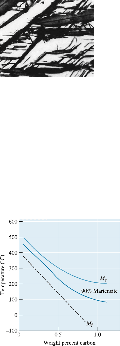
Retained Austenite There is a large volume expansion when martensite forms from
austenite. As the martensite plates form during quenching, they surround and iso-
late small pools of austenite (Figure 13-10), which deform to accommodate the lower-
density martensite. However, for the remaining pools of austenite to transform, the
surrounding martensite must deform. Because the strong martensite resists the trans-
formation, either the existing martensite cracks or the austenite remains trapped in the
structure as retained austenite. Retained austenite can be a serious problem. Martensite
softens and becomes more ductile during tempering. After tempering, the retained aus-
tenite cools below the M
s
and M
f
temperatures and transforms to martensite, since the
surrounding tempered martensite can deform. But now the steel contains more of the
hard, brittle martensite! A second tempering step may be needed to eliminate the mar-
tensite formed from the retained austenite. Retained austenite is also more of a problem
for high-carbon steels. The martensite start ðM
s
Þ and finish ðM
f
Þ temperatures are re-
duced when the carbon content increases (Figure 13-11). High-carbon steels must be
refrigerated to produce all martensite.
Figure 13-10
Retained austenite (white) trapped between
martensite needles (black) (1000). (From ASM
Handbook, Vol. 8, (1973), ASM International,
Materials Park, OH 44073.)
Figure 13-11
Increasing carbon reduces the M
s
and
M
f
temperatures in plain-carbon
steels.
13-4 Quench and Temper Heat Treatments 403
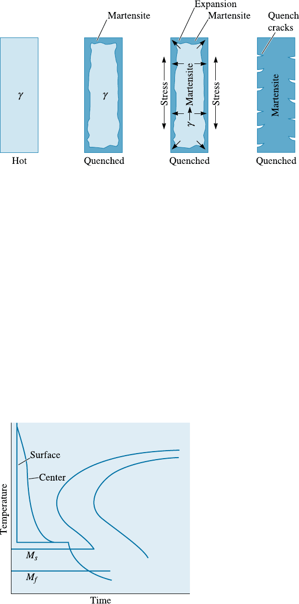
Residual Stresses and Cracking Residual stresses are also produced because of the
volume change or because of cold working. A stress-relief anneal can be used to remove
or minimize residual stresses due to cold working. Stresses are also induced because of
thermal expansion and contraction. In steels, there is one more mechanism that causes
stress. When steels are quenched, the surface of the quenched steel cools rapidly and
transforms to martensite. When the austenite in the center later transforms, the hard
surface is placed in tension, while the center is compressed. If the residual stresses
exceed the yield strength, quench cracks form at the surface (Figure 13-12). However, if
we first cool to just above the M
s
and hold until the temperature equalizes in the steel,
subsequent quenching permits all of the steel to transform to martensite at about the
same time. This heat treatment is called marquenching or martempering (Figure 13-13).
Note that, strictly speaking, the CCT diagrams should be used to examine non-isothermal
heat treatments. This will be discussed later in this section.
Figure 13-12 Formation of quench cracks caused by residual stresses produced during
quenching. The figure illustrates the development of stresses as the austenite transforms to
martensite during cooling.
Figure 13-13
The marquenching heat treatment,
designed to reduce residual stresses and
quench cracking.
C HA P T E R 1 3 Heat Treatment of Steels and Cast Irons404
Quench Rate In using the TTT diagram, we assumed that we could cool from the
austenitizing temperature to the transformation temperature instantly. Because this
does not occur in practice, undesired microconstituents may form during the quenching
process. For example, pearlite may form as the steel cools past the nose of the curve,
particularly because the time of the nose is less than one second in plain-carbon steels.
The rate at which the steel cools during quenching depends on several factors.
First, the surface always cools faster than the center of the part. In addition, as the size
of the part increases, the cooling rate at any locatio n is slower. Finally, the cooling rate
depends on the temperature and heat transfer characteristics of the quenching medium
(Table 13-2). Quenching in oil, for example, produces a lower H coe‰cient, or slower
cooling rate, than quenching in water or brine. The H coe‰cient is equivalent to the
heat transfer coe‰cient. Agitation helps break the vapor blanket (e.g., when water is
the quenching medium) and improves overall heat transfer rate by bringing cooler liq-
uid into contact with the parts being quenched.
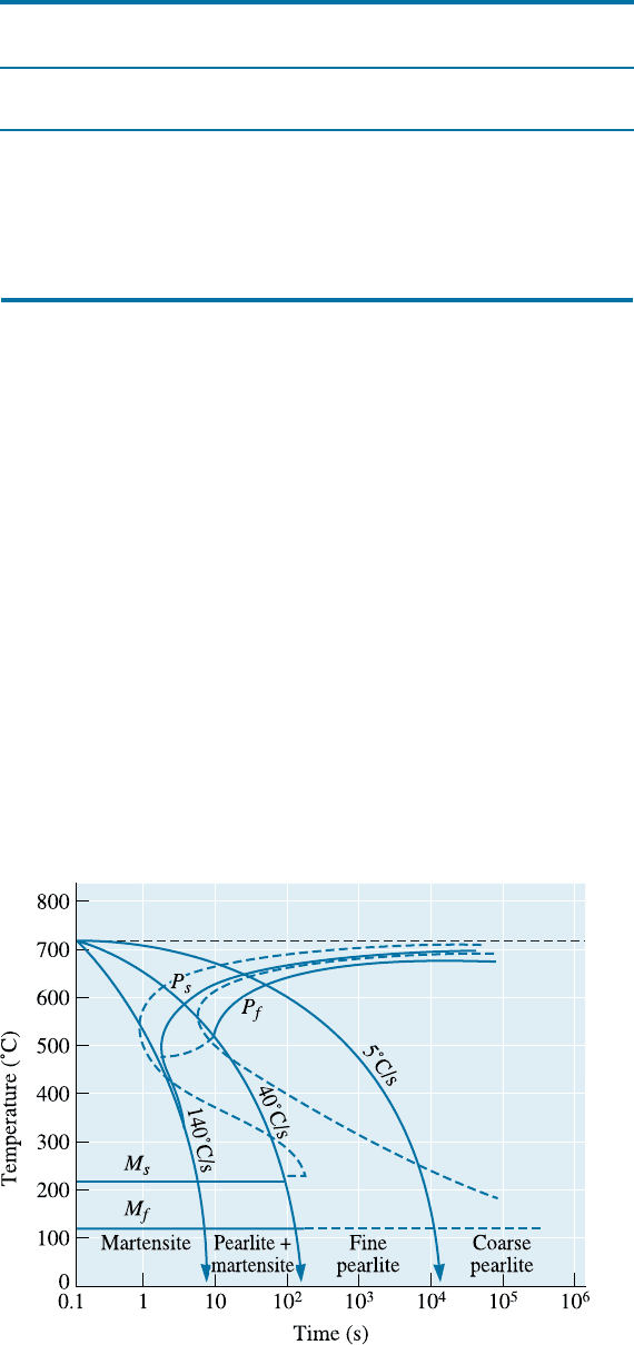
Continuous Cooling Transformation Diagrams We can develop a continuous cooling
transformation (CCT) diagram by determining the microstructures produced in the steel
at various rates of cooling. The CCT curve for a 1080 steel is shown in Figure 13-14.
TABLE 13-2 9 The H coefficient, or severity of the quench, for several
quenching media
Medium H Coefficient
Cooling Rate at the Center
of a 2.5 cm Bar (
˚
C/s)
Oil (no agitation) 0.25 18
Oil (agitation) 1.0 45
H
2
O (no agitation) 1.0 45
H
2
O (agitation) 4.0 190
Brine (no agitation) 2.0 90
Brine (agitation) 5.0 230
Figure 13-14
The CCT diagram (solid
lines) for a 1080 steel
compared with the TTT
diagram (dashed lines).
13-4 Quench and Temper Heat Treatments 405
The CCT diagram di¤ers from the TTT diagram in that longer times are required for
transformations to begin and no bainite region is observed.
If we cool a 1080 steel at 5
C/s, the CCT diagram tells us that we obtain coarse
pearlite; we have annealed the steel. Cooling at 35
C/s gives fine pearlite and is a nor-
malizing heat treatment. Cooling at 100
C/s permits pearlite to start forming, but the
reaction is incomplete and the remaining austenite changes to martensite. We obtain
100% martensite and thus are able to perform a quench and temper heat treatment,
only if we cool faster than 140
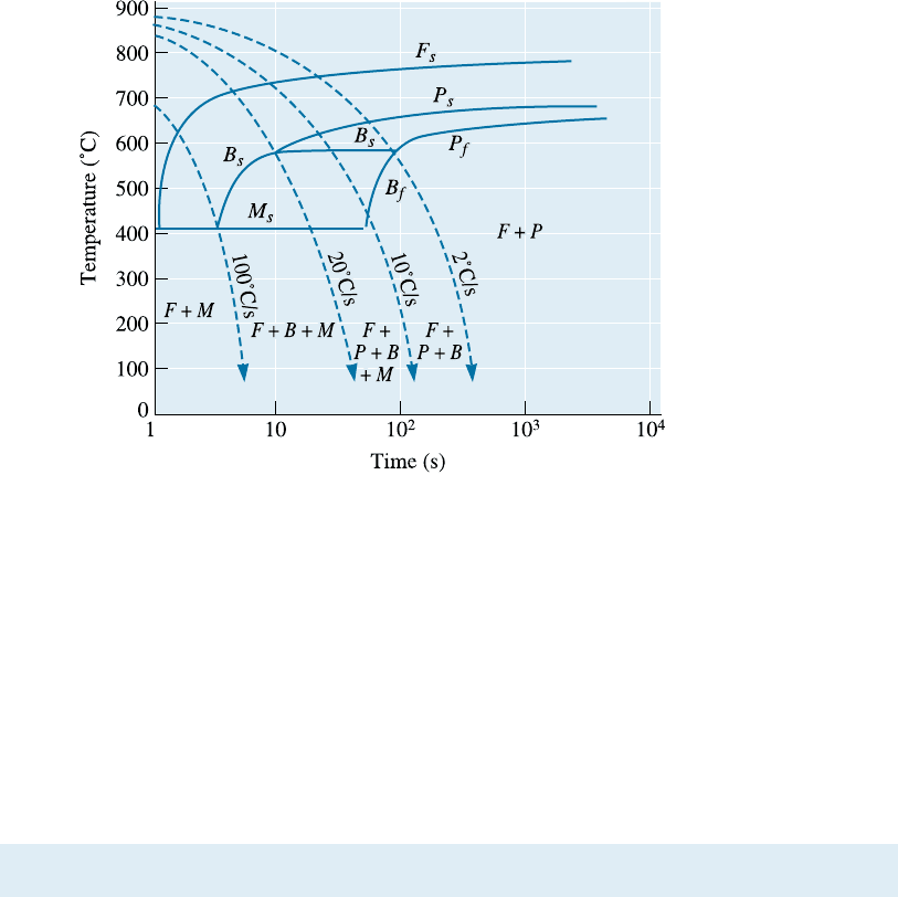
C/s. Other steels, such as the low-carbon steel in Figure
13-15, have more complicated CCT diagrams. In various handbooks, you can find a
compilation of TTT and CCT diagrams for di¤erent grades of steels.
13-5 Effect of Alloying Elements
Alloying elements are added to steels to (a) provide solid-solution strengthening of
ferrite, (b) cause the precipitation of alloy carbides rather than that of Fe
3
C, (c) im-
prove corrosion resistance and other special characteristics of the steel, and (d) improve
hardenability. The term hardenability describes the ease with which steels can form
martensite. This relates to how easily we can form martensite in a thick section of steel
that is quenched. With a more hardenable steel we can ‘‘get away’’ with a relatively
slow cooling rate and still form martensite. Improving hardenability is most important
in alloy and tool steels.
Hardenability In plain-carbon steels, the nose of the TTT and CCT curves occurs at
very short times; hence, very fast cooling rates are required to produce all martensite. In
thin sections of steel, the rapid quench produces distortion and cracking. In thick steels,
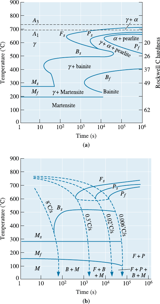
we are unable to produce martensite. All common alloying elements in steel shift the
TTT and CCT diagrams to longer times, permitting us to obtain all martensite even in
thick sections at slow cooling rates. Figure 13-16 shows the TTT and CCT curves for a
4340 steel.
Figure 13-15
The CCT diagram for a
low-alloy, 0.2% C steel.
C HA P T E R 1 3 Heat Treatment of Steels and Cast Irons406
Plain-carbon steels have low hardenability—only very high cooling rates produce
all martensite. Alloy steels have high hardenability—even cooling in air may produce
martensite. Hardenability does not refer to the hardness of the steel. A low-carbon,
high-alloy steel may easily form martensite but, because of the low-carbon content, the
martensite formed is not hard.
Figure 13-16 (a) TTT and (b) CCT curves for a 4340 steel.
13-5 Effect of All oying Elements 407
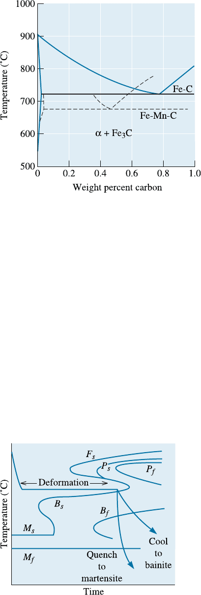
Effect on the Phase Stability When alloying elements are added to steel, the binary
Fe-Fe
3
C stability is a¤ected and the phase diagram is altered (Figure 13-17). Alloying
elements reduce the carbon content at which the eutectoid reaction occurs and change
the A
1
, A
3
, and A
cm
temperatures. A plain carbon steel containing only 0.6% C is
hypoeutectoid and would operate at 700
C without forming austenite; the otherwise
same steel containing 6% Mn is hypereutectoid and austenite forms at 700
C.
Shape of the TTT Diagram Alloying elements may introduce a ‘‘bay’’ region into the
TTT diagram, as in the case of the 4340 steel (Figure 13-16). The bay region is used as
the basis for a thermomechanical heat treatment known as ausforming. A steel can be
austenitized, quenched to the bay region, plastically deformed, and finally quenched to
produce martensite (Figure 13-18). Steels subjected to this treatment are known as aus-
formed steels.
Tempering Alloying elements reduce the rate of tempering compared with that of a
plain-carbon steel (Figure 13-19). This e¤ect may permit the alloy steels to operate
Figure 13-17
The effect of 6% manganese on the
stability ranges of the phases in the
eutectoid portion of the Fe-Fe
3
C phase
diagram.
Figure 13-18
When alloying elements introduce a bay
region into the TTT diagram, the steel can be
ausformed.
C HA P T E R 1 3 Heat Treatment of Steels and Cast Irons408
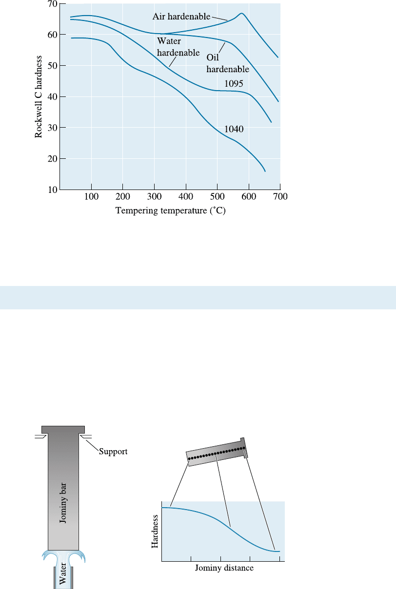
more successfully at higher temperatures than plain-carbon steels since overaging will
not occur during service.
13-6 Application of Hardenability
A Jominy test (Figure 13-20) is used to compare hardenabilities of steels. A steel bar
10-cm long and 2.5 cm in diameter is austenitized, placed into a fixture, and sprayed at
one end with water. This procedure produces a range of cooling rates—very fast at the
quenched end, almost air cooling at the opposite end. After the test, hardness meas-
urements are made along the test specimen and plotted to produce a hardenability curve
(Figure 13-21). The distance from the quenched end is the Jominy distance and is
related to the cooling rate (Table 13-3).
Figure 13-19
The effect of alloying
elements on the phases
formed during the
tempering of steels. The
air-hardenable steel
shows a secondary
hardening peak.
Figure 13-20
The set-up for the Jominy
test used for determining
the hardenability of a
steel.
13-6 Application of Hardenability 409