ALSTOM T&D. Network Protection And Automation Guide (NPAG)
Подождите немного. Документ загружается.

Chapter 19 AC Motor Protection
19-11
widely, from increased heating to stalling due to the reduced
torque available.
A typical setting for negative sequence current protection must
take into account the fact that the motor circuit protected by
the relay may not be the source of the negative sequence
current. Time should be allowed for the appropriate protection
to clear the source of the negative sequence current without
introducing risk of overheating to the motor being considered.
This indicates a two stage tripping characteristic, similar in
principle to overcurrent protection. A low-set definite time-
delay element can be used to provide an alarm, with an IDMT
element used to trip the motor in the case of higher levels of
negative sequence current, such as loss-of-phase conditions at
start, occurring. Typical settings might be 20% of CT rated
primary current for the definite time element and 50% for the
IDMT element. The IDMT time delay has to be chosen to
protect the motor while, if possible, grading with other
negative sequence relays on the system. Some relays may not
incorporate two elements, in which case the single element
should be set to protect the motor, with grading being a
secondary consideration.
19.8 FAULTS IN ROTOR WINDINGS
On wound rotor machines, some degree of protection against
faults in the rotor winding can be given by an instantaneous
stator current overcurrent relay element. As the starting
current is normally limited by resistance to a maximum of
twice full load, the instantaneous unit can safely be set to
about three times full load if a slight time delay of
approximately 30 milliseconds is incorporated. It should be
noted that faults occurring in the rotor winding would not be
detected by any differential protection applied to the stator.
19.9 RTD TEMPERATURE DETECTION
RTDs are used to measure temperatures of motor windings or
shaft bearings. A rise in temperature may denote overloading
of the machine, or the beginning of a fault in the affected part.
A motor protection relay will therefore usually have the
capability of accepting a number of RTD inputs and internal
logic to initiate an alarm and/or trip when the temperature
exceeds the appropriate setpoint(s). Occasionally, HV motors
are fed via a unit transformer, and in these circumstances,
some of the motor protection relay RTD inputs may be
assigned to the transformer winding temperature RTDs, thus
providing overtemperature protection for the transformer
without the use of a separate relay.
19.10 BEARING FAILURES
There are two types of bearings to be considered: the anti-
friction bearing (ball or roller), used mainly on small motors
(up to around 350kW), and the sleeve bearing, used mainly on
large motors.
The failure of ball or roller bearings usually occurs very quickly,
causing the motor to come to a standstill as pieces of the
damaged roller get entangled with the others. There is
therefore very little chance that any relay operating from the
input current can detect bearing failures of this type before the
bearing is completely destroyed. Therefore, protection is
limited to disconnecting the stalled motor rapidly to avoid
consequential damage. Refer to Section 19.4 on stall
protection for details of suitable protection.
Failure of a sleeve bearing can be detected by means of a rise
in bearing temperature. The normal thermal overload relays
cannot give protection to the bearing itself but will operate to
protect the motor from excessive damage. Use of RTD
temperature detection, as noted in Section 19.9, can provide
suitable protection, allowing investigation into the cause of the
bearing running hot prior to complete failure.
19.11 UNDERVOLTAGE PROTECTION
Motors may stall when subjected to prolonged undervoltage
conditions. Transient undervoltages will generally allow a
motor to recover when the voltage is restored, unless the
supply is weak.
Motors fed by contactors have inherent undervoltage
protection, unless a latched contactor is used. Where a
specific undervoltage trip is required, a definite time
undervoltage element is used. If two elements are provided,
alarm and trip settings can be used. An interlock with the
motor starter is required to block relay operation when the
starting device is open, otherwise a start will never be
permitted. The voltage and time delay settings will be system
and motor dependent. They must allow for all voltage dips
likely to occur on the system during transient faults, starting of
motors, etc. to avoid spurious trips. As motor starting can
result in a voltage depression to 80% of nominal, the voltage
setting is likely to be below this value. Re-acceleration is
normally possible for voltage dips lasting between 0.5-2
seconds, depending on system, motor and drive
characteristics, and therefore the time delay will be set bearing
these factors in mind.
19.12 LOSS-OF-LOAD PROTECTION
Loss-of-load protection has a number of possible functions. It
can be used to protect a pump against becoming unprimed, or
to stop a motor in case of a failure in a mechanical
transmission (e.g. conveyor belt), or it can be used with
synchronous motors to protect against loss-of-supply
conditions. Implementation of the function is by a low forward
© 2011 Alstom Grid. Single copies of this document may be filed or printed for personal non-commercial use and must include this
copyright notice but may not be copied or displayed for commercial purposes without the prior written permission of Alstom Grid.
Network Protection & Automation Guide
19-12
power relay element, interlocked with the motor starting
device to prevent operation when the motor is tripped and thus
preventing a motor start. When starting against a very low
load (e.g. a compressor), the function may also need to be
inhibited for the duration of the start, to prevent maloperation.
The setting will be influenced by the function to be performed
by the relay. A time delay may be required after pickup of the
element to prevent operation during system transients. This is
especially important for synchronous motor loss-of supply
protection.
19.13 ADDITIONAL PROTECTION FOR
SYNCHRONOUS MOTORS
The differences in construction and operational characteristics
of synchronous motors mean that additional protection is
required for these types of motor. This additional protection is
discussed in the following sections.
19.13.1 Out-of-Step Protection
A synchronous motor may decelerate and lose synchronism
(fall out-of-step) if a mechanical overload exceeding the peak
motor torque occurs. Other conditions that may cause this
condition are a fall in the applied voltage to stator or field
windings. Such a fall may not need to be prolonged, a voltage
dip of a few seconds may be all that is required. An out-of-
step condition causes the motor to draw excessive current and
generate a pulsating torque. Even if the cause is removed
promptly, the motor will probably not recover synchronism, but
eventually stall. Hence, it must be disconnected from the
supply.
The current drawn during an out-of-step condition is at a very
low power factor. Hence a relay element that responds to low
power factor can be used to provide protection. The element
must be inhibited during starting, when a similar low power
factor condition occurs. This can conveniently be achieved by
use of a definite time delay, set to a value slightly in excess of
the motor start time.
The power factor setting will vary depending on the rated
power factor of the motor. It would typically be 0.1 less than
the motor rated power factor i.e. for a motor rated at 0.85
power factor, the setting would be 0.75.
19.13.2 Protection against Sudden Restoration of
Supply
If the supply to a synchronous motor is interrupted, it is
essential that the motor breaker be tripped as quickly as
possible if there is any possibility of the supply being restored
automatically or without the machine operator’s knowledge.
This is necessary in order to prevent the supply being restored
out of phase with the motor generated voltage.
Two methods are generally used to detect this condition, in
order to cover different operating modes of the motor.
19.13.2.1 Underfrequency protection
The underfrequency relay element will operate in the case of
the supply failing when the motor is on load, which causes the
motor to decelerate quickly. Typically, two elements are
provided, for alarm and trip indications. The underfrequency
setting value needs to consider the power system
characteristics. In some power systems, lengthy periods of
operation at frequencies substantially below normal occur, and
should not result in a motor trip. The minimum safe operating
frequency of the motor under load conditions must therefore
be determined, along with minimum system frequency.
19.13.2.2 Low forward power protection
This can be applied in conjunction with a time delay to detect a
loss-of-supply condition when the motor may share a busbar
with other loads. The motor may attempt to supply the other
loads with power from the stored kinetic energy of rotation. A
low-forward-power relay can detect this condition. A time
delay will be required to prevent operation during system
transients leading to momentary reverse power flow in the
motor.
19.14 MOTOR PROTECTION EXAMPLES
This section gives examples of the protection of HV and LV
induction motors.
19.14.1 Protection of a HV Motor
Table 19.2 gives relevant parameters of a HV induction motor
to be protected. Using an Alstom MiCOM P241 motor
protection relay, the important protection settings are
calculated in the following sections.
Quantity Value
Rated output 1000kW CMR
Rated Voltage 3.3kV
Rated frequency 50Hz
Rated power factor/efficiency 0.9/0.92
Stall withstand time cold/hot 20/7 sec
Starting current 550% DOL
Permitted starts cold/hot 3/2
CT ratio 250/1
Start time at 100% voltage 4 sec
Start time at 80% voltage 5.5 sec
Heating/cooling time constant 25/75 mins
© 2011 Alstom Grid. Single copies of this document may be filed or printed for personal non-commercial use and must include this
copyright notice but may not be copied or displayed for commercial purposes without the prior written permission of Alstom Grid.
Chapter 19 AC Motor Protection
19-13
Quantity Value
System earthing Solid
Control device Circuit Breaker
Table 19.2: Example motor data
19.14.1.1 Thermal protection
The current setting
I
TH
is set equal to the motor full load
current, as it is a CMR rated (Continuous Maximum Rated)
motor. Motor full load current can be calculated as 211A,
therefore (in secondary quantities):
844.0
250
211
TH
I
Use a value of 0.85, nearest available setting.
The relay has a parameter,
K
, to allow for the increased
heating effect of negative sequence currents. In the absence of
any specific information, use
K
=
3.
Two thermal heating time constants are provided,
1
W
and
2
W
.
2
W
is used for starting methods other than DOL, otherwise it is
set equal to
1
W
.
1
W
is set to the heating time constant, hence
1
W
=
2
W
.=25min. Cooling time constant
R
W
is set as a
multiple of
1
W
. With a cooling time constant of 75min,
1
3
WW
u
R
.
19.14.1.2 Short circuit protection
Following the recommendations of Section 19.5, with a
starting current of 550% of full load current, the short-circuit
element is set to 1.25 x 5.5 x 211A = 1450A
.
In terms of the relay nominal current I
n
, the setting value is
n
I.85
250
1450
There is a minimum time delay of 100ms for currents up to
120% of setting to allow for transient CT saturation during
starting and 40ms above this current value. These settings are
satisfactory.
19.14.1.3 Earth-fault protection
It is assumed that no CBCT is fitted. A typical setting of 30% of
motor rated current is used, leading to an earth fault relay
setting of
n
I.. 250
250
211
30 u
A stabilising resistor is required, calculated in accordance with
Equation 19.2 to prevent maloperation due to CT spill current
during starting as the CTs may saturate. With the stabilising
resistor present, instantaneous tripping is permitted. The
alternative is to omit the stabilising resistor and use a definite
time delay in association with the earth-fault element.
However, the time delay must be found by trial and error
during commissioning.
19.14.1.4 Locked rotor/Excessive start time protection
The current element must be set in excess of the rated current
of the motor, but well below the starting current of the motor
to ensure that a start condition is recognised (this could also
be achieved by use of an auxiliary contact on the motor CB
wired to the relay). A setting of 500A
(2I
n
) is suitable. The
associated time delay needs to be set to longer than the start
time, but less than the cold stall time. Use a value of 15s.
19.14.1.5 Stall protection
The same current setting as for locked rotor protection can be
used – 500A. The time delay has to be less than the hot stall
time of 7s but greater than the start time by a sufficient
margin to avoid a spurious trip if the start time happens to be
a little longer than anticipated. Use a value of 6.5s.
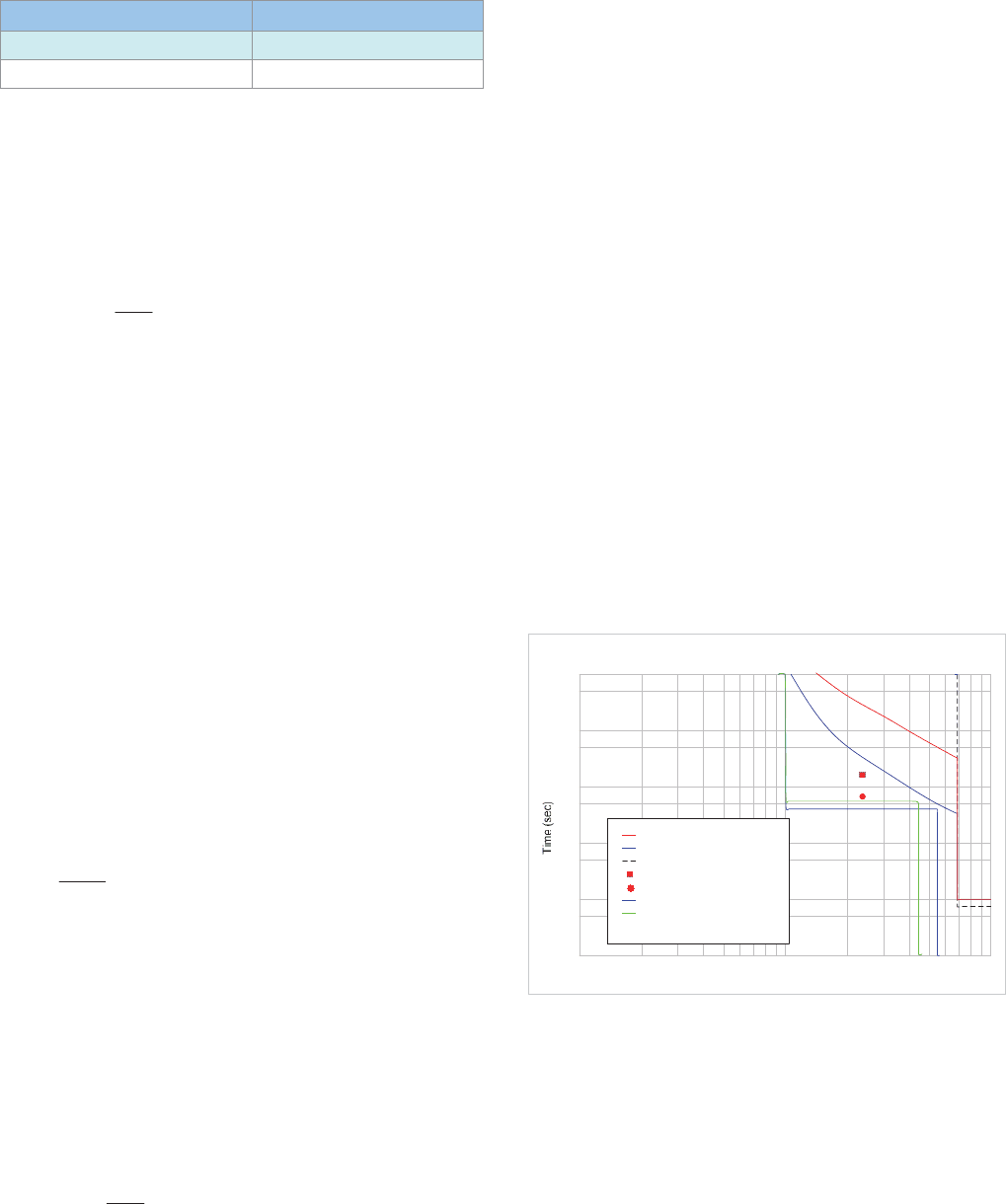
The protection characteristics for sections 19.14.1.1-5 are
shown in Figure 19.12.
1000
100
10
1
0.1
0.01
1
0.01
10
I
th
/I (p.u.)
Motor tripping characteristics.
Cold Thermal
Hot Thermal
S/C
Locked Rotor
Stall
S
t
a
r
t
C
u
r
r
e
n
t
(
1
0
0
%
V
)
S
t
a
r
t
C
u
r
r
e
n
t
(
8
0
%
V
)
Figure 19.12: Protection characteristics for motor protection example
19.14.1.6 Negative phase sequence protection
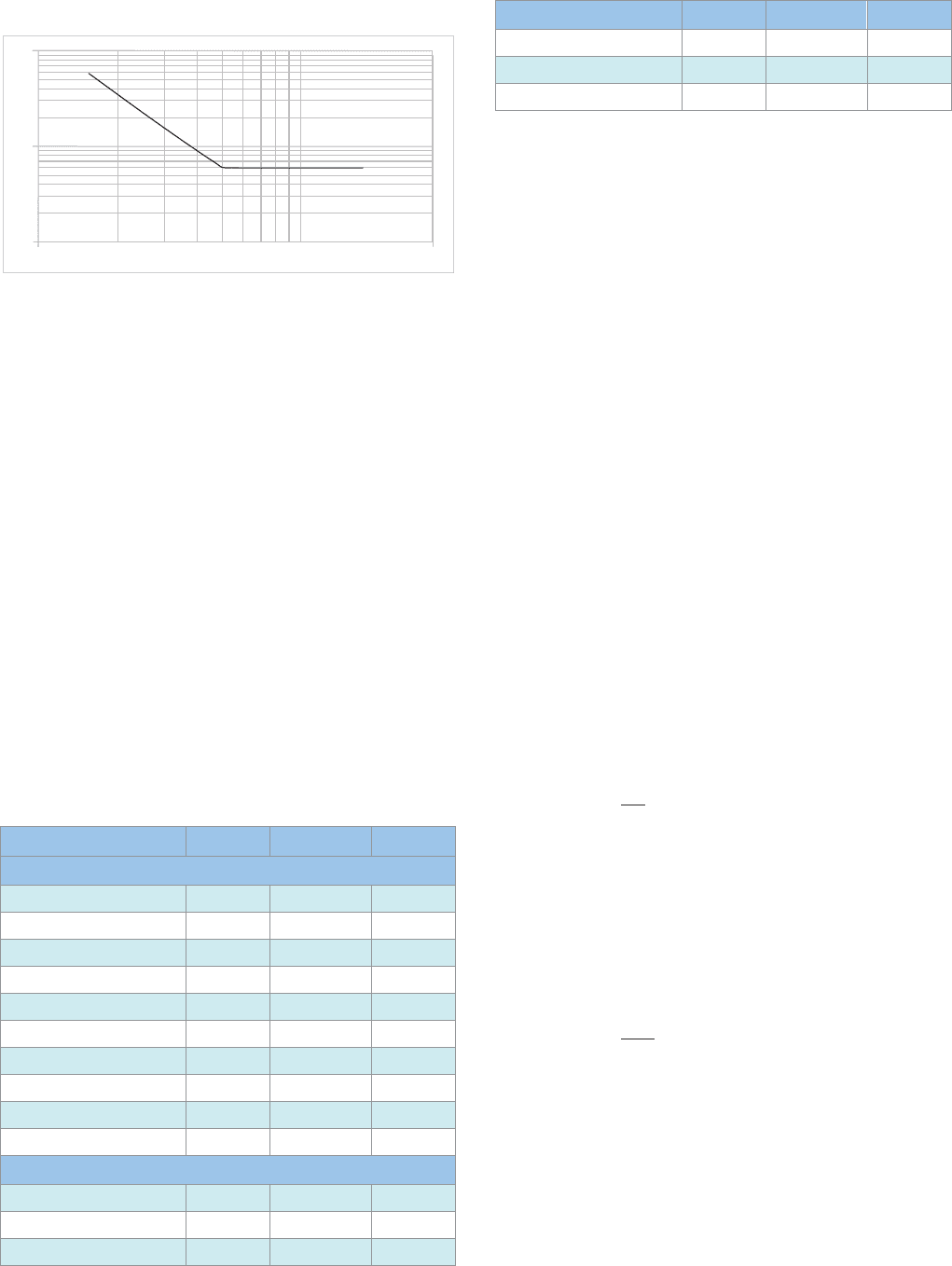
Two protection elements are provided, the first is definite time-
delayed to provide an alarm. The second is an IDMT element
used to trip the motor on high levels of negative sequence
current, such as would occur on a loss of phase condition at
starting. In accordance with Section 19.7, use a setting of 20%
with a time delay of 30s for the definite time element and 50%
with a TMS of 1.0 for the IDMT element. The resulting
characteristic is shown in Figure 19.13. The motor thermal
protection, as it utilises a negative sequence component, is
used for protection of the motor at low levels of negative
© 2011 Alstom Grid. Single copies of this document may be filed or printed for personal non-commercial use and must include this
copyright notice but may not be copied or displayed for commercial purposes without the prior written permission of Alstom Grid.
Network Protection & Automation Guide
19-14
sequence current.
Current (A)
10 10000
10
1
0.1
Time (sec)
Figure 19.13: Motor protection example- negative sequence
protection characteristic
19.14.1.7 Other protection considerations
If the relay can be supplied with a suitable voltage signal, stall
protection can be inhibited during re-acceleration after a
voltage dip using the undervoltage element (set to 80-85% of
rated voltage). Undervoltage protection (set to approximately
80% voltage with a time delay of up to several seconds,
dependent on system characteristics) and reverse phase
protection can also be implemented to provide extra
protection. Unless the drive is critical to the process, it is not
justifiable to provide a VT specially to enable these features to
be implemented.
19.14.2 Protection of an LV Motor
LV motors are commonly fed via fused contactors and
therefore the tripping times of a protection relay for
overcurrent must be carefully co-ordinated with the fuse to
ensure that the contactor does not attempt to break a current
in excess of its rating. Table 19.3(a) gives details of an LV
motor and associated fused contactor.
Parameter Symbol Value Unit
(a) LV motor example
Standard IEC 60034
Motor Voltage 400 V
Motor kW 75 kW
Motor kVA 91.45 kVA
Motor FLC 132 A
Starting Current 670 %
Starting Time 4.5 sec
Contactor rating 300 A
Contactor breaking capacity 650 A
Fuse rating 250 A
(b) Relay settings
Overcurrent Disabled -
Overload setting Ib 4.4 A
Overload time delay I>t 15 sec
Parameter Symbol Value Unit
Unbalance I2 20 %
Unbalance time delay I2>t 25 sec
Loss of phase time delay <Ip 5 sec
Table 19.3: LV motor protection setting example
19.14.2.1 CT ratio
The relay is set in secondary quantities, and therefore a
suitable CT ratio has to be calculated. From the relay manual,
a CT with 5A secondary rating and a motor rated current in the
range of 4-6A when referred to the secondary of CT is required.
Use of a 150/5A CT gives a motor rated current of 4.4A when
referred to the CT secondary, so use this CT ratio.
19.14.2.2 Overcurrent (short-circuit) protection
The fuse provides the motor overcurrent protection, as the
protection relay cannot be allowed to trip the contactor on
overcurrent in case the current to be broken exceeds the
contactor breaking capacity. The facility for overcurrent
protection within the relay is therefore disabled.
19.14.2.3 Thermal (overload) protection
The motor is an existing one, and no data exists for it except
the standard data provided in the manufacturer's catalogue.
This data does not include the thermal (heating) time constant
of the motor.
In these circumstances, it is usual to set the thermal protection
so that it lies just above the motor starting current.
The current setting of the relay,
b
I , is found using the formula
p
n
b
I
I
I
u 5
Where
n
I = motor rated primary current
p
I = CT primary current
Hence,
AI
b
4.4
150
132
5 u
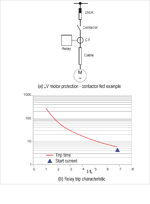
With a motor starting current of 670% of nominal, a setting of
the relay thermal time constant with motor initial thermal
state of 50% of 15s is found satisfactory, as shown in Figure
19.14.
© 2011 Alstom Grid. Single copies of this document may be filed or printed for personal non-commercial use and must include this
copyright notice but may not be copied or displayed for commercial purposes without the prior written permission of Alstom Grid.
Chapter 19 AC Motor Protection
19-15
Time (sec)
Figure 19.14: Motor protection example – contactor-fed motor
19.14.2.4 Negative sequence (phase unbalance)
protection
The motor is built to IEC standards, which permit a negative
sequence (unbalance) voltage of 1% on a continuous basis.
This would lead to approximately 7% negative sequence current
in the motor (Section 19.7). As the relay is fitted only with a
definite time relay element, a setting of 20% (from Section
19.7) is appropriate, with a time delay of 25s to allow for short
high-level negative sequence transients arising from other
causes.
19.14.2.5 Loss of phase protection
The relay has a separate element for this protection. Loss of a
phase gives rise to large negative sequence currents, and
therefore a much shorter time delay is required. A definite
time delay of 5s is considered appropriate.
The relay settings are summarised in Table 19.3(b).
© 2011 Alstom Grid. Single copies of this document may be filed or printed for personal non-commercial use and must include this
copyright notice but may not be copied or displayed for commercial purposes without the prior written permission of Alstom Grid.

© 2011 Alstom Grid. Single copies of this document may be filed or printed for personal non-commercial use and must include this
copyright notice but may not be copied or displayed for commercial purposes without the prior written permission of Alstom Grid.
Alstom Grid 20-1
Chapter 20
System Integrity Protection Schemes
20.1 Introduction
20.2 Summary of System Integrity Protection
Schemes
20.3 Time-Synchronised System Integrity Protection
Schemes
20.4 Non-Synchronised System Integrity Protection
Schemes
20.5 References
20.1 INTRODUCTION
Operating electric power systems is continually becoming more
complex. Increasing challenges are posed as the systems are
operated closer to their stability limits. Electrical power
systems continue to expand, integrating new components such
as renewable energy sources, distributed generation and
independent power producers, in an increasingly open energy
market. Regulatory pressure has power system operators'
attention focused to grow return on investment of their assets
whilst power consumption is increasing and many power
system infrastructures are ageing.
In the wake of deregulation, electricity markets load the grid in
a less predictable and more dynamic way, while generation
companies’ decisions do not always account for transmission
constraints.
Stability margins are narrowing since the system is being
pushed to operate closer to its limits, and forecasting
operational data is getting more difficult as grids connect over
increasingly larger geographical footprints.
The result is that when things do go wrong, they can have a
dramatic effect with cascade tripping and blackouts.
20.1.1 Blackouts
In 1965, 25 million people in parts of the United States and
Canada lost their electricity supply for about 12 hours. The
failure was attributed to a maintenance error and carries the
reputable distinction of being the first large scale blackout. It is
not an isolated event. Leaving aside ‘planned’ disruptions
caused by, for example civil unrest such as the miners’ strike in
the UK in 1974, there are many such events that have caused
disruption that is, at the least inconvenient, generally
commercially damaging, and at worst, life-threatening.
In 1978, 80 percent of France was affected by a blackout
caused by the breakdown of a transmission line.
In 1989, a geomagnetic storm caused an outage that left 6
million people in Québec, Canada without power for nine
hours.
In 1999 a major blackout was triggered in Brazil following a
lightning strike. Over 90 million people were affected.
In August 2003, a wide-area power collapse in the north of the
United States of America and central Canada affected 50
© 2011 Alstom Grid. Single copies of this document may be filed or printed for personal non-commercial use and must include this
copyright notice but may not be copied or displayed for commercial purposes without the prior written permission of Alstom Grid.
Network Protection & Automation Guide
20-2
million people. It is estimated to have cost billions of dollars,
and at least eleven fatalities were attributed to the loss of
power.
During the miners' strike of 1974, energy and electrical power
systems had been at the forefront of the political agenda in the
UK. The devastation caused by the North American blackout
put electrical power systems onto the world political agenda.
Supply of electrical energy had become, to many, no longer a
luxury, but a basic human need.
Large-scale blackouts have continued since that time in
countries including Australia, Japan, Peru, Greece, Russia and
Italy, but technology is being developed and deployed to help
prevent future occurrences.
Scenarios of major blackouts are hardly ever the same. The
starting event may be a generation-load imbalance, a short
circuit, human actions (or inaction), unexpected grid topology
changes, lack of voltage support, or natural causes such as
lightning storms or untrimmed trees. What they all share is a
resulting failure process that cascades.
Occasionally, to prevent network components from
overloading, parts of a power system automatically disconnect
or shut down to avoid damage and isolate the problem
component from the rest of the network. Under certain
conditions, the shutdown of the component can cause
significant current fluctuations or overloads in the remaining
segments of the network. These fluctuations may propagate
and amplify, leading to uncontrollable power system dynamic
oscillations and cascading failure, which spreads to wider parts
of the network and, in some cases, the entire grid.
20.1.2 Preserving Supply
Although rare, these widespread blackouts and their collection
of critical consequences on business, public safety (lighting),
public comfort (heating/air conditioning), telecommunications,
etc., have driven the industry to develop automatic control
systems to mitigate the occurrence of such large-scale failures
caused by unexpected events. Modern power systems are
designed and equipped to be resistant to this sort of cascading
failure. Facilities and tools, which embed such resistance,
include energy management system technology and system
integrity protection schemes also known as special protection
schemes, remedial action schemes, or wide area schemes.
Electrical power systems are designed and operated to
withstand contingencies that are likely to occur as a result of a
single event. Such events are sometimes referred to as class 1,
or N-1 type contingencies. For these contingencies protection
is likely to be afforded by relays applied to individual items of
plant.
A combination of simultaneous events could be classified as a
class 2, or N-2 type contingency, and a cascading event as a
class 3, or N-3 contingency.
For N-2 and N-3 contingencies, system level action is
required. This could involve generator tripping (possibly on a
massive scale), load shedding or, ultimately, coordinated
system separation, to preserve system stability and/or prevent
serious damage to transmission and generation equipment.
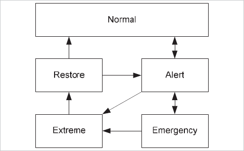
As well as the N- contingencies, another way of looking at the
system operation is by means of the state diagram introduced
by Fink and Carlsen [20.1] as shown in Figure 20.1.
Figure 20.1: Fink Carlsen diagram
In this model, conventional protection and control is likely to
be effective in the ‘alert’ and ‘emergency’ states where the
load capacity and generating capacity remain matched. In the
‘extreme’ state, they are no longer matched and system
integrity protection schemes are required.
Remedial actions performed by system integrity protection
schemes are the second and third lines in the plan to protect
the system.
20.1.3 Enabling Technologies
System integrity protection schemes have advanced thanks to
technological developments, which have been widely adopted
by the industry. Three technological developments in
particular that have brought great benefit and advances in the
field of measurement, protection, control and automation of
electrical power systems are:
x advances in embedded computing
x wide-area communications and
x accurate time synchronisation
This chapter explores at how these enabling technologies can
enhance the measuremen
t of power system quantities,
enabling wide-area monitoring and control, and ‘bigger
picture’ protection solutions.
© 2011 Alstom Grid. Single copies of this document may be filed or printed for personal non-commercial use and must include this
copyright notice but may not be copied or displayed for commercial purposes without the prior written permission of Alstom Grid.
Chapter 20 System Integrity Protection Schemes
20-3
20.2 SUMMARY OF SYSTEM INTEGRITY
PROTECTION SCHEMES
System integrity protection schemes (or 'special protection
schemes', 'remedial action schemes', and in some cases
'wide-area schemes'), are tools to protect the system. Unlike
conventional protection relays where the purpose is to isolate
faulted plant, system integrity protection schemes initiate
actions to correct the system. Typical system stress scenarios
that a system integrity protection scheme might be required to
act upon include:
x transient instability
x voltage degradation
x frequency degradation
x thermal overloading
x loss of synchronism
x large power swings
x cascade of overloads
To implement effective, intelligent system integrity protection
schemes appropriate for the prevailing power system
condition, it is essential that real time system data is made
available.
Using this data, a system
integrity protection scheme can
initiate:
x generator tripping
x load rejection
x controlled system separation
x voltage clamping
x modification to the operational state of FACTS devices
x etc.
As with conventional protection the consequences of failing to
operate when required, or
operating when not required could
be catastrophic and so system integrity protection schemes
must be carefully designed. Four main design criteria
applicable to system integrity protection schemes are [20.2]:
x Dependability:– The certainty that the system integrity
protection scheme operates when required, that is, in
all cases where emergency controls are required to
avoid a collapse.
x Security:– The certain
ty that the system integrity
protection scheme will not operate when not required,
i.e. does not a
pply emergency controls unless they are
necessary to avoid a collapse.
x Selectivity:– The ability to select the correct and
minimum action to perform the intended function.
That is, to avoi
d using disruptive controls such as load
shedding if they are not necessary to avoid a collapse.
x Robustness:– The ability of the system integrity
protection scheme to provide dependability, security
and selectivity over the full range of
dynamic and steady
state operating conditions that it will encounter.
Conformance to these criteria is critical to the deployment of
system integrity protection schemes.
Under normal system operation, the measures that a system
integrity protection scheme may initiate will be inactive. They
are activated when some system disturbance or stress
condition occurs.
In terms of detection principles, system integrity protection
schemes may be classified in two different categories: event-
based and response based. Event-based systems act to detect
the cause(s) of a disturbance; Response-based systems
respond to the effects. Typically, event based systems will
automatically activate remedial actions and will operate
quickly. Response based systems may activate the remedial
actions either automatically or manually, and longer operating
times may apply.
System integrity protection schemes may exist in stand-alone
devices, using local quantities only to provide fast acting
decisions, or they may take quantities from a wider area of the
system. The latter will have longer operating times as it relies
on the communication of data between source of acquisition
and decision-maker. Additionally, system integrity protection
schemes may be made at the highest system level and be part
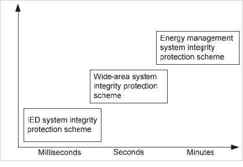
of the energy management suite as shown in Figure 20.2.
Local Centralised
Figure 20.2: System integrity protection schemes residency and typical
operating times.
Examples of IED (Intelligent Electronic Device) system integrity
protection schemes include detecting changes to topology, and
detecting loss of synchronism.
An example of a wide-area system integrity protection scheme
is monitoring angular stability across the system and taking
© 2011 Alstom Grid. Single copies of this document may be filed or printed for personal non-commercial use and must include this
copyright notice but may not be copied or displayed for commercial purposes without the prior written permission of Alstom Grid.
Network Protection & Automation Guide
20-4
actions necessary to correct. Energy management system
integrity protection schemes can be used to take a more
‘static’ view, looking at long term phenomena.
Implementing system integrity protection schemes requires
real time data. When that data is coming from different
sources it is crucial that the data is synchronised, and that it
can be communicated effectively and efficiently. It is the
possibility to accurately synchronise devices and to rapidly
communicate the data that makes time-synchronised system
integrity protection schemes possible.
20.3 TIME-SYNCHRONISED SYSTEM
INTEGRITY PROTECTION SCHEMES
As discussed briefly in chapter 10, timing information from the
global positioning satellite system (GPS) can be used to
synchronise current differential unit protection and merging
units (chapter 24). The GPS system consists of a number of
satellites in space that are continually transmitting
information.
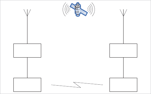
The basic principle of using the GPS system to synchronise
current differential protection is shown in Figure 20.3. This is
an example of a communication-assisted scheme with a
practical application.
GPS
Receiver
GPS
Receiver
IED at
end A
IED at
end B
Communications link
Figure 20.3: GPS timing synchronisation for current differential
protection.
The basis of the scheme described by Figure 20.3 is that the
GPS signals are picked up by antennae connected to
synchronising units. These synchronising units decode the
information to produce a highly accurate timing signal that
synchronises the current signals used by the relays to perform
the current differential algorithm. The timing signal presented
to the relays is in the form of a pulse that is transmitted at the
start of every second. This one pulse per second (1pps) is
more than sufficiently accurate for multi-ended current
differential protection and it is a logical progression to use the
same accuracy of GPS timing information to synchronise the
measurements of power system quantities across the whole
grid.
The GPS 1pps signal can be used to synchronise the
measurement of anything from anywhere in the world. In the
electrical power system it can be used to synchronise the
measurement of voltage and current from key nodes on the
grid to enhance the monitoring and control of the grid.
So called phasor measurement units are synchronised using
the GPS timing to produce time-synchronised phasor
representations of the current and voltage signals that they
take as input. These time-synchronised phasor
representations, or synchrophasors, can be collected from
different nodes on the grid and compared to get a wide-area
system-level view.
Current and voltage synchrophasors from phasor
measurement units can be used to observe the state of the
system and improve the performance of different system level
applications. Using synchrophasors to observe, measure, or
monitor the system is sometimes termed ‘wide-area
monitoring’ or WAM. Control actions taken on the basis of the
interpretation of these WAMs is sometimes termed ‘wide-area
control’, or WAC, and protection action taken on the WAMs is
sometimes termed ‘wide-area protection’, or WAP. System
integrity protection schemes based on wide-area technology
are essentially control schemes. It is perhaps unwise to try to
differentiate the application of wide-area technology to the
separate fields of monitoring, control, and protection, rather to
combine them into a single heading of ‘wide-area monitoring,
protection and control’, or WAMPAC.
20.3.1 Wide-area Monitoring, Protection and Control
(WAMPAC) System Integrity Protection Schemes
A wide-area scheme to accommodate system integrity
protection could consist of phasor measurement units to
generate the synchrophasor data signals. These signals need
to be collected together before system level applications are
exercised. Collection of synchrophasors is typically performed
by a phasor data concentrator (PDC) which prepares the
synchrophasor data for the application.
Wide-area technology based on synchrophasors can be used
to enhance state estimation and provides opportunities for
WAMPAC schemes as shown in Figure 20.4.
© 2011 Alstom Grid. Single copies of this document may be filed or printed for personal non-commercial use and must include this
copyright notice but may not be copied or displayed for commercial purposes without the prior written permission of Alstom Grid.
