ALSTOM T&D. Network Protection And Automation Guide (NPAG)
Подождите немного. Документ загружается.


Alstom Grid 19-1
Chapter 19
AC Motor Protection
19.1 Introduction
19.2 Modern Relay Design
19.3 Thermal (Overload) Protection
19.4 Start/Stall Protection
19.5 Short-Circuit Protection
19.6 Earth Fault Protection
19.7 Negative Phase Sequence Protection
19.8 Faults in Rotor Windings
19.9 RTD Temperature Detection
19.10 Bearing Failures
19.11 Undervoltage Protection
19.12 Loss-of-load Protection
19.13 Additional Protection for Synchronous Motors
19.14 Motor Protection Examples
19.1 INTRODUCTION
There are a wide range of a.c. motors and motor
characteristics in existence, because of the numerous duties for
which they are used. All motors need protection, but
fortunately, the more fundamental problems affecting the
choice of protection are independent of the type of motor and
the type of load to which it is connected. There are some
important differences between the protection of induction
motors and synchronous motors, and these are fully dealt with
in section 19.3.
Motor characteristics must be carefully considered when
applying protection; while this may be regarded as stating the
obvious, it is emphasised because it applies more to motors
than to other items of power system plant. For example, the
starting and stalling currents/times must be known when
applying overload protection, and furthermore the thermal
withstand of the machine under balanced and unbalanced
loading must be clearly defined.
The conditions for which motor protection is required can be
divided into two broad categories: imposed external conditions
and internal faults. Table 19.1 provides details of most likely
faults that require protection.
External Faults Internal faults
Unbalanced supplies Bearing failures
Undervoltages Winding faults
Single phasing Overloads
Reverse phase sequence
Table 19.1: Causes of motor failures
19.2 MODERN RELAY DESIGN
The design of a modern numerical motor protection relay must
be adequate to cater for the protection needs of any one of the
vast range of motor designs in service, many of the designs
having no permissible allowance for overloads. A relay offering
comprehensive protection will have the following set of
features:
Synchronous and asynchronous motors
x thermal protection
x extended start protection
x stalling protection
x number of starts limitation
x short circuit protection
© 2011 Alstom Grid. Single copies of this document may be filed or printed for personal non-commercial use and must include this
copyright notice but may not be copied or displayed for commercial purposes without the prior written permission of Alstom Grid.

Network Protection & Automation Guide
19-2
x earth fault protection
x winding RTD measurement/trip
x negative sequence current detection
x undervoltage protection
x loss-of-load protection
x auxiliary supply supervision
Synchronous motors only
x out-of-step protection
x loss of supply protection
In addition, relays may offer options such as circuit breaker
condition m
onitoring as an aid to maintenance.
Manufacturers may also offer relays that implement a reduced
functionality to that given above where less comprehensive
protection is warranted (e.g. induction motors of low rating).
The following sections examine each of the possible failure
modes of a motor and discuss how protection may be applied
to detect that mode.
19.3 THERMAL (OVERLOAD) PROTECTION
The majority of winding failures are either indirectly or directly
caused by overloading (either prolonged or cyclic), operation
on unbalanced supply voltage, or single phasing, which all lead
through excessive heating to the deterioration of the winding
insulation until an electrical fault occurs. The generally
accepted rule is that insulation life is halved for each 10ºC rise
in temperature above the rated value, modified by the length of
time spent at the higher temperature. As an electrical machine
has a relatively large heat storage capacity, it follows that
infrequent overloads of short duration may not adversely affect
the machine. However, sustained overloads of only a few
percent may result in premature ageing and insulation failure.
Furthermore, the thermal withstand capability of the motor is
affected by heating in the winding prior to a fault. It is
therefore important that the relay characteristic takes account
of the extremes of zero and full-load pre-fault current known
respectively as the 'Cold' and 'Hot' conditions.
The variety
of motor designs, diverse applications, variety of
possible abnormal operating conditions and resulting modes of
failure result in a complex thermal relationship. A generic
mathematical model that is accurate is therefore impossible to
create. However, it is possible to develop an approximate
model if it is assumed that the motor is a homogeneous body,
creating and dissipating heat at a rate proportional to
temperature rise. This is the principle behind the ‘thermal
replica’ model of a motor used for overload protection.
The temperature T at any instant is given by:
¸
¸
¹
·
¨
¨
©
§
W
t
max
eTT 1
where:
max
T = final steady state temperature
W
= heating time constant
Temperature rise is proportional to the current squared:
¸
¸
¹
·
¨
¨
©
§
W
t
R
eKIT 1
2
where:
R
I = current which, if flowing continuously, produces
temperature
max
T in the motor
Therefore, it can be shown that, for any overload current
I ,
the permissible time
t for this current to flow is:
»
»
»
»
»
¼
º
«
«
«
«
«
¬
ª
°
¿
°
¾
½
°
¯
°
®
¸
¹
·
¨
©
§
2
1
1
log
I
I
t
R
e
W
In general, the supply to which a motor is connected may
contain both positive and negative sequence components, and
both components of current give rise to heating in the motor.
Therefore, the thermal replica should take into account both of
these components, a typical equation for the equivalent current
being:
2
2
2
1
KIII
eq
where
1
I = positive sequence current
2
I = negative sequence current
K = negative sequence rotor resistance / positive sequence
rotor resistance at rated speed.
A typical value of K is 3.
Finally, the thermal replica model needs to take into account
the fact that the motor will tend to cool down during periods of
light load, and the initial state of the motor. The motor will
have a cooling time constant,
W
r
, that defines the rate of
cooling. Hence, the final thermal model can be expressed as:
© 2011 Alstom Grid. Single copies of this document may be filed or printed for personal non-commercial use and must include this
copyright notice but may not be copied or displayed for commercial purposes without the prior written permission of Alstom Grid.
Chapter 19 AC Motor Protection
19-3
1
log
2
22
K
AK
t
e
W
Equation 19.1
where:
W
= heating time constant
th
eq
I
I
K
2
A = initial state of motor (cold or hot)
th
I = thermal setting current
Equation 19.1 takes into account the ‘cold’ and ‘hot’
characteristics defined in IEC 60255, part 8.
Some relays may use a dual curve characteristic for the
heating time constant, and hence two values of the heating
time constant are required. Switching between the two values
takes place at a pre-defined motor current. This may be used
to obtain better tripping performance during starting on
motors that use a star-delta starter. During starting, the
motor windings carry full line current, while in the ‘run’
condition, they carry only 57% of the current seen by the relay.
Similarly, when the motor is disconnected from the supply, the
heating time constant
W
is set equal to the cooling time
constant
r
W
.
Since the relay should ideally be matched to the protected
motor and be capable of close sustained overload protection, a
wide range of relay adjustment is desirable together with good
accuracy and low thermal overshoot.
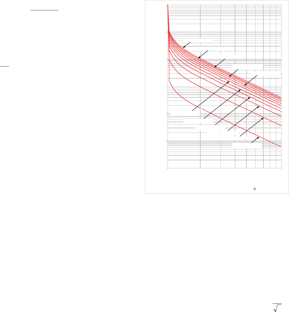
Typical relay setting curves are shown in Figure 19.1.
1
0
1
10
100
1000
10 000
100 000
10
T
e1
= T
e2
= 60min
T
e1
= T
e2
= 54min
T
e1
= T
e2
= 48min
T
e1
= T
e2
= 42min
T
e1
= T
e2
= 36min
T
e1
= T
e2
= 30min
T
e1
= T
e2
= 24min
T
e1
= T
e2
= 18min
T
e1
= T
e2
= 12min
T
e1
= T
e2
= 6min
T
e1
= T
e2
= 1min
Thermal equivalent current I
eq
in terms of the
current thermal threshold I
>
Operating time (seconds)
Figure 19.1: Thermal overload characteristic curves from cold – initial
thermal state 0%
19.4 START/STALL PROTECTION
When a motor is started, it draws a current well in excess of
full load rating throughout the period that the motor takes to
run-up to speed. While the motor starting current reduces
somewhat as motor speed increases, it is normal in protection
practice to assume that the motor current remains constant
throughout the starting period. The starting current will vary
depending on the design of the motor and method of starting.
For motors started DOL (direct-on-line), the nominal starting
current can be 4-8 times full-load current. However, when a
star-delta starter is used, the line current will only be
3
1
of
the DOL starting current.
Should a motor stall whilst running, or fail to start, due to
excessive loading, the motor will draw a current equal to its
locked rotor current. It is not therefore possible to distinguish
between a stall condition and a healthy start solely on the basis
of the current drawn. Discrimination between the two
conditions must be made based on the duration of the current
drawn. For motors where the starting time is less than the
safe stall time of the motor, protection is easy to arrange.
However, where motors are used to drive high inertia loads,
© 2011 Alstom Grid. Single copies of this document may be filed or printed for personal non-commercial use and must include this
copyright notice but may not be copied or displayed for commercial purposes without the prior written permission of Alstom Grid.
Network Protection & Automation Guide
19-4
the stall withstand time can be less than the starting time. In
these cases, an additional means must be provided to enable
discrimination between the two conditions to be achieved.
19.4.1 Excessive Start Time/Locked Rotor Protection
A motor may fail to accelerate from rest for a number of
reasons:
x loss of a supply phase
x mechanical problems
x low supply voltage
x excessive load torque
x etc.
A large current will be drawn from the supply, and cause
extremely high temperatures to be generated within the mo
tor.
This is made worse by the fact that the motor is not rotating,
and hence no cooling due to rotation is available. Winding
damage will occur very quickly – either to the stator or rotor
windings depending on the thermal limitations of the
particular design (motors are said to be stator or rotor limited
in this respect). The method of protection varies depending on
whether the starting time is less than or greater than the safe
stall time. In both cases, initiation of the start may be sensed
by detection of the closure of the switch in the motor feeder
(contactor or CB) and optionally current rising above a starting
current threshold value – typically 200% of motor rated
current. For the case of both conditions being sensed, they
may have to occur within a narrow aperture of time for a start
to be recognised.
Special requirements may exist for certain types of motors
installed in hazardous areas (e.g. motors with type of
protection EEx ‘e’) and the setting of the relay must take these
into account. Sometimes a permissive interlock for machine
pressurisation (on EEx ‘p’ machines) may be required, and this
can be conveniently achieved by use of a relay digital input and
the in-built logic capabilities.
19.4.1.1 Start time < safe stall time
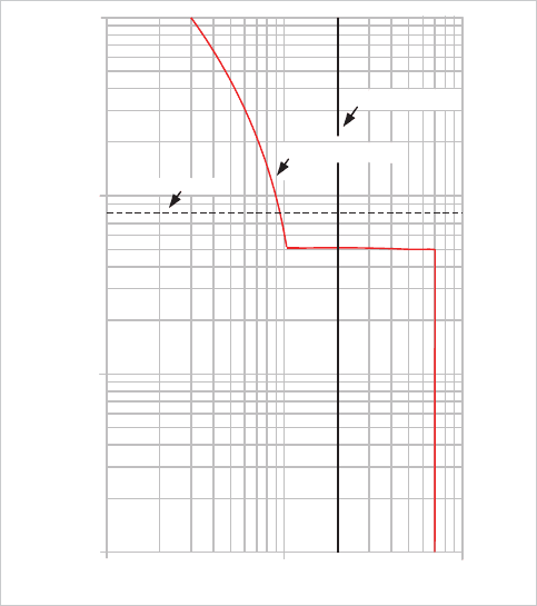
Protection is achieved by use of a definite time overcurrent
characteristic, the current setting being greater than full load
current but less than the starting current of the machine. The
time setting should be a little longer than the start time, but
less than the permitted safe starting time of the motor. Figure
19.2 illustrates the principle of operation for a successful start.
0.1
0.1
Time (s)
1
10
Relay time setting
Current (p.u.)
Relay current setting
100
110
Motor starting current
Figure 19.2: Relay setting for successful start: start time<stall time
19.4.1.2 Start time t safe stall time
For this condition, a definite time overcurrent characteristic by
itself is not sufficient, since the time delay required is longer
than the maximum time that the motor can be allowed to
carry starting current safely. An additional means of detection
of rotor movement, indicating a safe start, is required. A
speed-sensing switch usually provides this function. Detection
of a successful start is used to select the relay timer used for
the safe run-up time of the motor. This time can be longer
than the safe stall time, as there is both a (small) decrease in
current drawn by the motor during the start and the rotor fans
begin to improve cooling of the machine as it accelerates. If a
start is sensed by the relay through monitoring current and/or
start device closure, but the speed switch does not operate, the
relay element uses the safe stall time setting to trip the motor
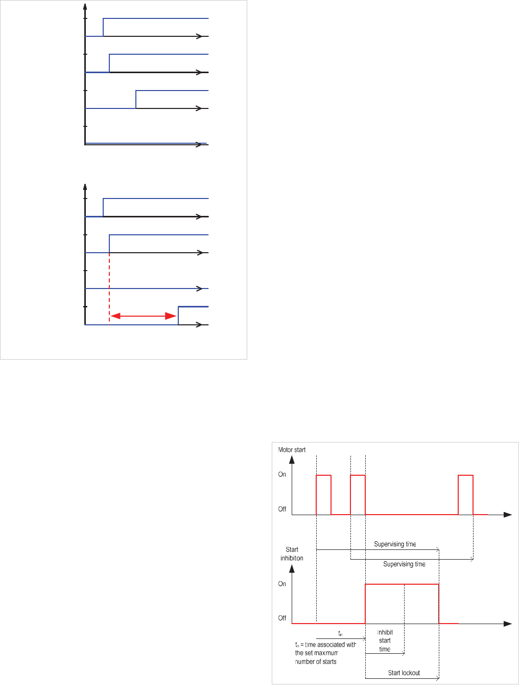
before damage can occur. Figure 19.3(a) illustrates the
principle of operation for a successful start, and Figure 19.3(b)
for an unsuccessful start.
© 2011 Alstom Grid. Single copies of this document may be filed or printed for personal non-commercial use and must include this
copyright notice but may not be copied or displayed for commercial purposes without the prior written permission of Alstom Grid.
Chapter 19 AC Motor Protection
19-5
Speed
switch
information
0
1
1
0
1
0
0
1
Stall time setting
command
Trip
Current
CB closed
(b) Unsuccessful start
0
(a) Successful start
Trip
command
0
1
switch
Speed
information
Current
0
1
1
CB closed
0
1
Time
Time
Time
Time
Time
Time
Time
Time
Figure 19.3: Relay settings for start time> stall time
19.4.2 Stall Protection
Should a motor stall when running or be unable to start
because of excessive load, it will draw a current from the
supply equivalent to the locked rotor current. It is obviously
desirable to avoid damage by disconnecting the machine as
quickly as possible if this condition arises.
Motor stalling can be recognised by the motor current
exceeding the start current threshold after a successful start –
i.e. a motor start has been detected and the motor current has
dropped below the start current threshold within the motor
safe start time. A subsequent rise in motor current above the
motor starting current threshold is then indicative of a stall
condition, and tripping will occur if this condition persists for
greater than the setting of the stall timer. An instantaneous
overcurrent relay element provides protection.
In many systems, transient supply voltage loss (typically up to
2 seconds) does not result in tripping of designated motors.
They are allowed to re-accelerate upon restoration of the
supply. During re-acceleration, they draw a current similar to
the starting current for a period that may be several seconds.
It is thus above the motor stall relay element current threshold.
The stall protection would be expected to operate and defeat
the object of the re-acceleration scheme. A motor protection
relay will therefore recognise the presence of a voltage dip and
recovery, and inhibit stall protection for a defined period. The
undervoltage protection element (section 19.11) can be used
to detect the presence of the voltage dip and inhibit stall
protection for a set period after voltage recovery. Protection
against stalled motors in case of an unsuccessful re-
acceleration is therefore maintained. The time delay setting is
dependent on the re-acceleration scheme adopted and the
characteristics of individual motors. It should be established
after performing a transient stability study for the re-
acceleration scheme proposed.
19.4.3 Number of Starts Limitation
Any motor has a restriction on the number of starts that are
allowed in a defined period without the permitted winding, etc.
temperatures being exceeded. Starting should be blocked if
the permitted number of starts is exceeded. The situation is
complicated by the fact the number of permitted ‘hot’ starts in
a given period is less than the number of ‘cold’ starts, due to
the differing initial temperatures of the motor. The relay must
maintain a separate count of ‘cold’ and ‘hot’ starts. By
making use of the data held in the motor thermal replica, ‘hot’
and ‘cold’ starts can be distinguished.
To allow the motor to cool down between starts, a time delay
may be specified between consecutive starts (again
distinguishing between ‘hot’ and ‘cold’ starts). The start
inhibit is released after a time determined by the motor
specification.
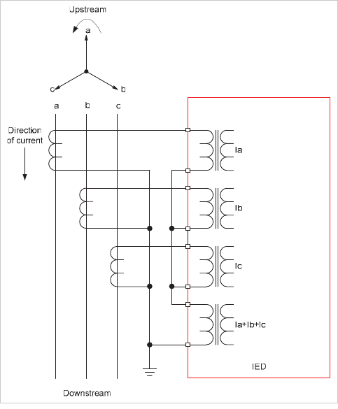
The overall protection function is illustrated in Figure 19.4.
Figure 19.4: Number of starts limitation
© 2011 Alstom Grid. Single copies of this document may be filed or printed for personal non-commercial use and must include this
copyright notice but may not be copied or displayed for commercial purposes without the prior written permission of Alstom Grid.
Network Protection & Automation Guide
19-6
In this example, the maximum number of starts within the
Supervising Time has been reached, therefore the Inhibit Start
Time is initiated. The remaining time is greater than the
Inhibit Start Time, so the start inhibition remains for a duration
equal to the supervising time minus the
t
n
.
19.5 SHORT-CIRCUIT PROTECTION
Motor short-circuit protection is often provided to cater for
major stator winding faults and terminal flashovers. Because
of the relatively greater amount of insulation between phase
windings, faults between phases seldom occur. As the stator
windings are completely enclosed in grounded metal the fault
would very quickly involve earth, which would then operate the
instantaneous earth fault protection. A single definite time
overcurrent relay element is all that is required for this
purpose, set to about 125% of motor starting current. The time
delay is required to prevent spurious operation due to CT spill
currents, and is typically set at 100ms. If the motor is fed from
a fused contactor, co-ordination is required with the fuse, and
this will probably involve use of a long time delay for the relay
element. Since the object of the protection is to provide rapid
fault clearance to minimise damage caused by the fault, the
protection is effectively worthless in these circumstances. It is
therefore only provided on motors fed via circuit breakers.
Differential (unit) protection may be provided on larger HV
motors fed via circuit breakers to protect against phase-phase
and phase-earth faults, particularly where the power system is
resistance-earthed. The differential protection can be made
quite sensitive allowing early detection of faults, thus damage
to the motor can be minimised. The normal definite time
overcurrent protection would not be sufficiently sensitive, and
sensitive earth fault protection may not be provided. The user
may wish to avoid the detailed calculations required of
capacitance current in order to set sensitive non-directional
earth fault overcurrent protection correctly on HV systems
(Chapter 9) or there may be no provision for a VT to allow
application of directional sensitive earth fault protection. There
is still a lower limit to the setting that can be applied, due to
spill currents from CT saturation during starting, while on
some motors, neutral current has been found to flow during
starting, even with balanced supply voltages, that would cause
the differential protection to operate. For details on the
application of differential protection, refer to Chapter 10.
However, non-directional earth fault overcurrent protection
will normally be cheaper in cases where adequate sensitivity
can be provided.
19.6 EARTH FAULT PROTECTION
One of the most common faults to occur on a motor is a stator
winding fault. Whatever the initial form of the fault (phase-
phase, etc.) or the cause (cyclic overheating, etc.), the
presence of the surrounding metallic frame and casing will
ensure that it rapidly develops into a fault involving earth.
Therefore, provision of earth fault protection is very important.
The type and sensitivity of protection provided depends largely
on the system earthing, so the various types will be dealt with
in turn. It is common, however, to provide both instantaneous
and time-delayed relay elements to cater for major and slowly
developing faults.
19.6.1 Solidly-Earthed System
Most LV systems fall into this category, for reasons of
personnel safety. Two types of earth fault protection are
commonly found – depending on the sensitivity required.
For applications where a sensitivity of > 20% of motor
continuous rated current is acceptable, conventional earth
fault protection using the residual CT connection of Figure
19.5 can be used. A lower limit is imposed on the setting by
possible load unbalance and/or (for HV systems) system
capacitive currents.
Figure 19.5: Residual CT connection for earth fault protection
Care must be taken to ensure that the relay does not operate
from the spill current resulting from unequal CT saturation
during motor starting, where the high currents involved will
almost certainly saturate the motor CT’s. It is common to use
a stabilising resistor in series with the relay, with the value
being calculated using the formula:
© 2011 Alstom Grid. Single copies of this document may be filed or printed for personal non-commercial use and must include this
copyright notice but may not be copied or displayed for commercial purposes without the prior written permission of Alstom Grid.
Chapter 19 AC Motor Protection
19-7
rlct
st
stab
RkRR
I
I
R
0
Equation 19.2
where:
st
I = starting current referred to CT secondary
0
I = relay earth fault setting (A)
stab
R =stabilising resistor value (ohms)
ct
R =dc resistance of CT secondary (ohms)
l
R =CT single lead resistance (ohms)
r
R = relay resistance (ohms)
k = CT connection factor (1 for star point at CT, 2 for star
point at relay).
The effect of the stabilising resistor is to increase the effective
setting of the relay under these conditions, and hence delay
tripping. When a stabilising resistor is used, the tripping
characteristic should normally be instantaneous. An
alternative technique, avoiding the use of a stabilising resistor
is to use a definite time delay characteristic. The time delay
used will normally have to be found by trial and error, as it
must be long enough to prevent maloperation during a motor
start, but short enough to provide effective protection in case
of a fault.
Co-ordination with other devices must also be considered. A
common means of supplying a motor is via a fused contactor.
The contactor itself is not capable of breaking fault current
beyond a certain value, which will normally be below the
maximum system fault current – reliance is placed on the fuse
in these circumstances. As a trip command from the relay
instructs the contactor to open, care must be taken to ensure
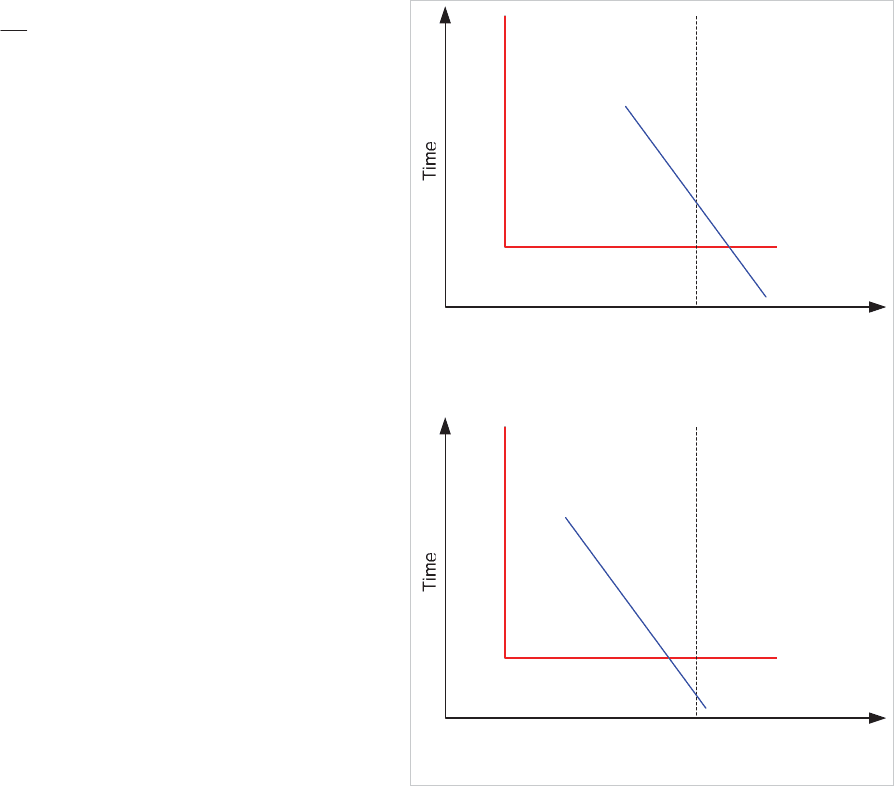
that this does not occur until the fuse has had time to operate.
Figure 19.6(a) illustrates incorrect grading of the relay with the
fuse, the relay operating first for a range of fault currents in
excess of the contactor breaking capacity. Figure 19.6(b)
illustrates correct grading. To achieve this, it may require the
use of an intentional definite time delay in the relay.
(a) Incorrect
Current
Contact
breaking
capacity
Earth Fault relay
Fuse
(b) Correct
Current
Contact
breaking
capacity
Earth Fault relay
Fuse
Figure 19.6: Grading of relay with fused contactor
If a more sensitive relay setting is required, it is necessary to
use a core-balance CT (CBCT). This is a ring type CT, through
which all phases of the supply to the motor are passed, plus
the neutral on a four-wire system. The turns ratio of the CT is
no longer related to the normal line current expected to flow,
so can be chosen to optimise the pick-up current required.
Magnetising current requirements are also reduced, with only
a single CT core to be magnetised instead of three, thus
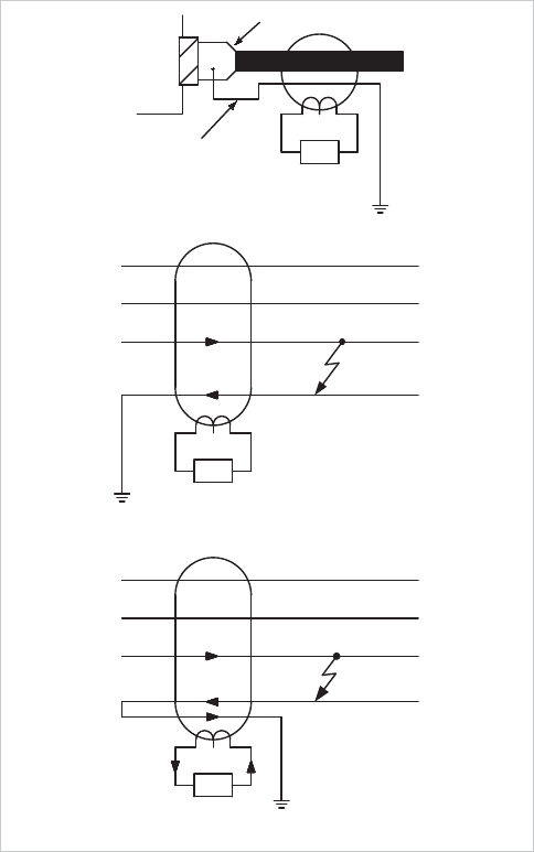
enabling low settings to be used. Figure 19.7 illustrates the
application of a core-balance CT, including the routing of the
cable sheath to ensure correct operation in case of core-sheath
cable faults.
© 2011 Alstom Grid. Single copies of this document may be filed or printed for personal non-commercial use and must include this
copyright notice but may not be copied or displayed for commercial purposes without the prior written permission of Alstom Grid.
Network Protection & Automation Guide
19-8
SEF
Cable gland /sheath
ground connection
Cable gland
Cable box
SEF
No operation
(b) Incorrect wiring
Operation
SEF
(c) Correct wiring
(a) Connection
Figure 19.7: Application of core-balance CT
19.6.2 Resistance-Earthed Systems
These are commonly found on HV systems, where the
intention is to limit damage caused by earth faults through
limiting the earth-fault current that can flow. Two methods of
resistance earthing are commonly used:
19.6.2.1 Low resistance earthing
In this method, the value of resistance is chosen to limit the
fault current to a few hundred amps – values of 200A-400A
being typical. With a residual connection of line CT’s, the
minimum sensitivity possible is about 10% of CT rated primary
current, due to the possibility of CT saturation during starting.
For a core-balance CT, the sensitivity that is possible using a
simple non-directional earth fault relay element is limited to
three times the steady-state charging current of the feeder.
The setting should not be greater than about 30% of the
minimum earth fault current expected. Other than this, the
considerations in respect of settings and time delays are as for
solidly earthed systems.
19.6.2.2 High resistance earthing
In some HV systems, high resistance earthing is used to limit
the earth fault current to a few amps. In this case, the system
capacitive charging current will normally prevent conventional
sensitive earth fault protection being applied, as the magnitude
of the charging current will be comparable with the earth fault
current in the event of a fault. The solution is to use a sensitive
directional earth fault relay. A core balance CT is used in
conjunction with a VT measuring the residual voltage of the
system, with a relay characteristic angle setting of +45ºC (see
Chapter 9 for details). The VT must be suitable for the relay
and therefore the relay manufacturer should be consulted over
suitable types – some relays require that the VT must be able
to carry residual flux and this rules out use of a 3-limb, 3-
phase VT. A setting of 125% of the single phase capacitive
charging current for the whole system is possible using this
method. The time delay used is not critical but must be fast
enough to disconnect equipment rapidly in the event of a
second earth fault occurring immediately after the first.
Minimal damage is caused by the first fault, but the second
effectively removes the current limiting resistance from the
fault path leading to very large fault currents.
An alternative technique using residual voltage detection is
also possible, and is described in the next section.
19.6.3 Insulated Earth System
Earth fault detection presents problems on these systems since
no earth fault current flows for a single earth fault. However,
detection is still essential as overvoltages occur on sound
phases and it is necessary to locate and clear the fault before a
second occurs. Two methods are possible:
x detection of the resulting unbalance in system charging
currents
x residual overvoltage.
19.6.3.1 System charging current unbalance
Sensitive earth fault protection using a core-balance CT is
required for this scheme. The principle is the same as already
detailed, except that the voltage is phase shifted by +90ºC
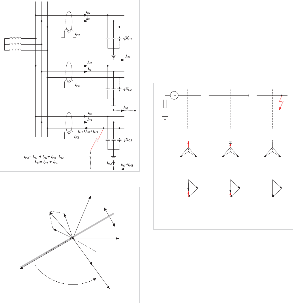
instead of -90ºC. To illustrate this, Figure 19.8 shows the
current distribution in an Insulated system subjected to a C-
phase to earth fault and Figure 19.9 the relay vector diagram
for this condition. The residual current detected by the relay is
the sum of the charging currents flowing in the healthy part of
the system plus the healthy phase charging currents on the
faulted feeder – i.e. three times the per phase charging current
of the healthy part of the system. A relay setting of 30% of this
value can be used to provide protection without the risk of a
trip due to healthy system capacitive charging currents. As
© 2011 Alstom Grid. Single copies of this document may be filed or printed for personal non-commercial use and must include this
copyright notice but may not be copied or displayed for commercial purposes without the prior written permission of Alstom Grid.
Chapter 19 AC Motor Protection
19-9
there is no earth fault current, it is also possible to set the relay
at site after deliberately applying earth faults at various parts of
the system and measuring the resulting residual currents.
If it is possible to set the relay to a value between the charging
current on the feeder being protected and the charging current
for the rest of the system, the directional facility is not required
and the VT can be dispensed with.
The comments made in section 19.6.1 regarding grading with
fused contactors also apply.
Figure 19.8: Current distribution in insulated-earth system for phase-
earth fault
An RCA setting of +90° shifts
the MTA to here
V
cpf
V
bpf
V
bf
Operate
Restrain
V
af
I
b1
V
apf
I
R1
I
a1
V
res
(=-3V
o
)
I
R
3
=
-
(
I
H
1
+
I
H
2
)
Figure 19.9: Relay vector diagram
19.6.3.2 Residual voltage method
A single earth fault results in a rise in the voltage between
system neutral and earth, which may be detected by a relay
measuring the residual voltage of the system (normally zero for
a perfectly balanced, healthy system). Thus, no CTs are
required, and the technique may be useful where provision of
an extensive number of core-balance CTs is impossible or
difficult, due to physical constraints or on cost grounds. The
VTs used must be suitable for the duty, thus 3-limb, 3-phase
VTs are not suitable, and the relay usually has alarm and trip
settings, each with adjustable time delays. The setting voltage
must be calculated from knowledge of system earthing and
impedances, an example for a resistance-earthed system is
shown in Figure 19.10.
Grading of the relays must be carried out with care, as the
residual voltage will be detected by all relays in the affected
section of the system. Grading has to be carried out with this
in mind, and will generally be on a time basis for providing
alarms (1
st
stage), with a high set definite time trip second
stage to provide backup.
Z
S
A - G
L
Z
Z
E
N
E
SRF
S
G,F
R
G,F
S
G,F
R
S
V
RES
V
A-G
V
C-G
V
B-G
V
RES
V
C-G
u
SO E
RES
S1 SO L1 L O E
Z3Z
V3E
2Z Z 2Z Z 3Z
V
C-G
V
B-G
V
RES
V
A-G
V
B-G
V
B-G
V
C-G
V
B-G
V
C-G
V
A-G
V
B-G
V
C-G
V
A-G
Figure 19.10: Residual voltage earth-fault protection for resistance-
earthed system
19.6.4 Petersen Coil Earthed System
Earthing of a HV power system using a reactor equal to the
system shunt capacitance is known as Petersen Coil (or
resonant coil) earthing. With this method, a single earth fault
results in zero earth fault current flowing (for perfect balance
between the earthing inductance and system shunt
capacitance), and hence the system can be run in this state for
a substantial period of time while the fault is located and
© 2011 Alstom Grid. Single copies of this document may be filed or printed for personal non-commercial use and must include this
copyright notice but may not be copied or displayed for commercial purposes without the prior written permission of Alstom Grid.
Network Protection & Automation Guide
19-10
corrected. The detailed theory and protection method is
explained in Section 9.19.
19.7 NEGATIVE PHASE SEQUENCE
PROTECTION
Negative phase sequence current is generated from any
unbalanced voltage condition, such as unbalanced loading,
loss of a single phase, or single-phase faults. The latter will
normally be detected by earth-fault protection, however, a
fault location in a motor winding may not result in the earth
fault protection operating unless it is of the sensitive variety.
The actual value of the negative sequence current depends on
the degree of unbalance in the supply voltage and the ratio of
the negative to the positive sequence impedance of the
machine. The degree of unbalance depends on many factors,
but the negative sequence impedance is more easily
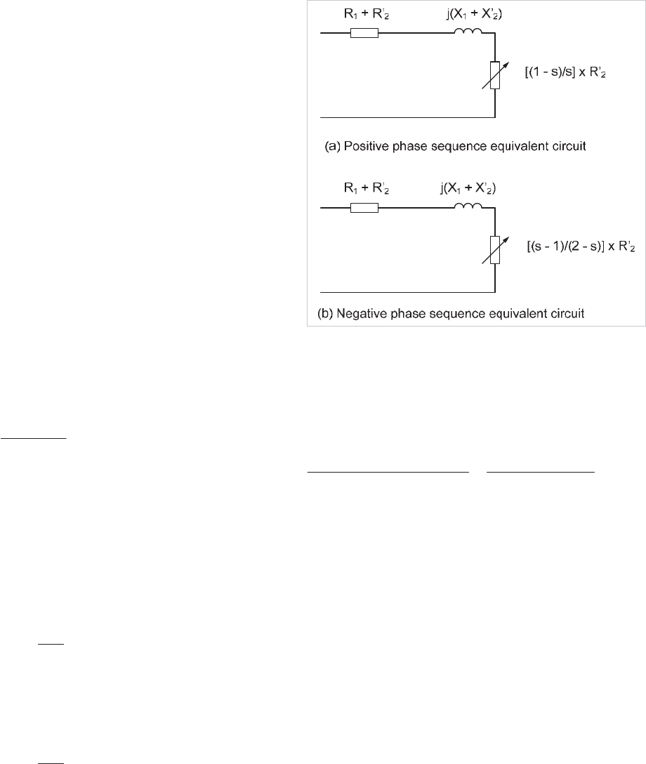
determined. Considering the classical induction motor
equivalent circuit with magnetising impedance neglected of
Figure 19.11:
Motor positive sequence impedance at slip s:
50
2
21
2
21
2
.
'
pp
pp
XX
s
RR
»
»
¼
º
«
«
¬
ª
¸
¸
¹
·
¨
¨
©
§
Hence, at standstill (s=1.0), impedance
>@
50
2
21
2
21
.
'
pp
'
pp
XXRR
The motor negative sequence impedance at slip s
50
2
21
2
2
1
.
'
nn
'
n
n
XX
S
R
R
»
»
¼
º
«
«
¬
ª
¸
¸
¹
·
¨
¨
©
§
and, at normal running speed, the impedance
50
2
21
2
2
1
2
.
'
nn
'
n
n
XX
R
R
»
»
¼
º
«
«
¬
ª
¸
¸
¹
·
¨
¨
©
§
where:
x suffix p indicates positive sequence quantities
and
x suffix n indicates negative sequence quantities
Figure 19.11: Induction motor equivalent circuits
The resistance can be neglected as it is small compared with
the reactance. Thus the negative sequence reactance at
running speed is approximately equal to the positive sequence
reactance at standstill. An alternative more meaningful way of
expressing this is:
currentrated
currentstarting
impedance.seqnegative
impedance.seqpositive
A typical LV motor starting current is 6 x full load current
(FLC). Therefore, a 5% negative sequence voltage (due to, say,
unbalanced loads on the system) would produce a 30%
negative sequence current in the machine, leading to excessive
heating. For the same motor, negative sequence voltages in
excess of 17% will result in a negative sequence current larger
than rated full load current.
Negative sequence current is at twice supply frequency. Skin
effect in the rotor means that the heating effect in the rotor of
a given negative sequence current is larger than the same
positive sequence current. Thus, negative sequence current
may result in rapid heating of the motor. Larger motors are
more susceptible in this respect, as the rotor resistance of such
machines tends to be higher. Protection against negative
sequence currents is therefore essential.
Modern motor protection relays have a negative sequence
current measurement capability, in order to provide such
protection. The level of negative sequence unbalance depends
largely upon the type of fault. For loss of a single phase at
start, the negative sequence current will be 50% of the normal
starting current. It is more difficult to provide an estimate of
the negative sequence current if loss of a phase occurs while
running. This is because the impact on the motor may vary
© 2011 Alstom Grid. Single copies of this document may be filed or printed for personal non-commercial use and must include this
copyright notice but may not be copied or displayed for commercial purposes without the prior written permission of Alstom Grid.
