ALSTOM T&D. Network Protection And Automation Guide (NPAG)
Подождите немного. Документ загружается.

Chapter 18 Industrial and Commercial Power System Protection
18-11
motors which are running down under these conditions, very
high inrush currents may result, producing stresses which
could be of sufficient magnitude to cause mechanical damage,
as well as a severe dip in the alternative supply voltage.
Two methods of automatic transfer are used:
x in-phase transfer system
x residual voltage system
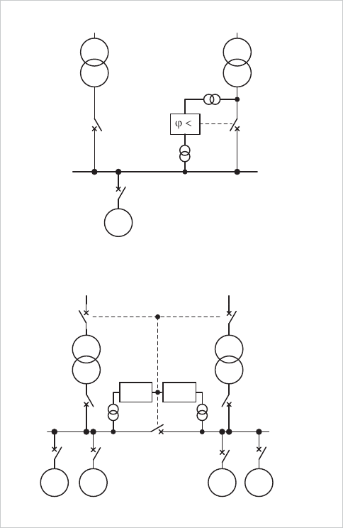
The in-phase transfer method is shown in Figure 18.11(a).
Normal and st
andby feeders from the same power source are
used.
Phase angle measurement is used to sense the relative phase
angle between the standby feeder voltage and the motor
busbar voltage. When the voltages are approximately in
phase, or just prior to this condition through prediction, a high-
speed circuit breaker is used to complete the transfer. This
method is restricted to large high inertia drives where the
gradual run down characteristic upon loss of normal feeder
supply can be predicted accurately.
(a) In phase transfer method
M
High speed
CB
angle
Phase
relay
feeder
Preferred Standby
feeder
(b) Residual voltage method
M
Feeder
No.1
Feeder
No.2
M MM
U
rsd
< U
rsd
<
Figure 18.11: Auto-transfer systems
Figure 18.11(b) shows the residual voltage method, which is
more common, especially in the petrochemical industry.
Two feeders are used, supplying two busbar sections
connected by a normally open bus section breaker. Each
feeder is capable of carrying the total busbar load. Each bus
section voltage is monitored and loss of supply on either
section causes the relevant incomer CB to open. Provided
there are no protection operations to indicate the presence of a
busbar fault, the bus section breaker is closed automatically to
restore the supply to the unpowered section of busbar after the
residual voltage generated by the motors running down on
that section has fallen to a an acceptable level. This is
between 25% and 40%, of nominal voltage, dependent on the
characteristics of the power system. The choice of residual
voltage setting will influence the re-acceleration current after
the bus section breaker closes. For example, a setting of 25%
may be expected to result in an inrush current of around 125%
of the starting current at full voltage. Alternatively, a time
delay could be used as a substitute for residual voltage
measurement, which would be set with knowledge of the plant
to ensure that the residual voltage would have decayed
sufficiently before transfer is initiated.
The protection relay settings for the switchboard must take
account of the total load current and the voltage dip during the
re-acceleration period in order to avoid spurious tripping
during this time. This time can be several seconds where large
inertia HV drives are involved.
18.10 VOLTAGE AND PHASE REVERSAL
PROTECTION
Voltage relays have been widely used in industrial power
supply systems. The principle purposes are to detect
undervoltage and/or overvoltage conditions at switchboards to
disconnect supplies before damage can be caused from these
conditions or to provide interlocking checks. Prolonged
overvoltage may cause damage to voltage-sensitive equipment
(e.g. electronics), while undervoltage may cause excessive
current to be drawn by motor loads. Motors are provided with
thermal overload protection to prevent damage with excessive
current, but undervoltage protection is commonly applied to
disconnect motors after a prolonged voltage dip. With a
voltage dip caused by a source system fault, a group of motors
could decelerate to such a degree that their aggregate re-
acceleration currents might keep the recovery voltage
depressed to a level where the machines might stall. Modern
numerical motor protection relays typically incorporate voltage
protection functions, thus removing the need for discrete
undervoltage relays for this purpose (see Chapter 19). Older
installations may still utilise discrete undervoltage relays, but
the setting criteria remain the same.
© 2011 Alstom Grid. Single copies of this document may be filed or printed for personal non-commercial use and must include this
copyright notice but may not be copied or displayed for commercial purposes without the prior written permission of Alstom Grid.
Network Protection & Automation Guide
18-12
Reverse phase sequence voltage protection should be applied
where it may be dangerous for a motor to be started with
rotation in the opposite direction to that intended. Incorrect
rotation due to reverse phase sequence might be set up
following some error after power system maintenance or
repairs, e.g. to a supply cable. Older motor control boards
might have been fitted with discrete relays to detect this
condition. Modern motor protection relays may incorporate
this function. If reverse phase sequence is detected, motor
starting can be blocked. If reverse phase sequence voltage
protection is not provided, the high-set negative phase
sequence current protection in the relay would quickly detect
the condition once the starting device is closed – but initial
reverse rotation of the motor could not be prevented.
18.11 POWER FACTOR CORRECTION AND
PROTECTION OF CAPACITORS
Loads such as induction motors draw significant reactive
power from the supply system, and a poor overall power factor
may result. The flow of reactive power increases the voltage-
drops through series reactances such as transformers and
reactors, it uses up some of the current carrying capacity of
power system plant and it increases the resistive losses in the
power system.
To offset the losses and restrictions in plant capacity they incur
and to assist with voltage regulation, Utilities usually apply
tariff penalties to large industrial or commercial customers for
running their plant at excessively low power factor. The
customer is thereby induced to improve the power factor of his
system and it may be cost-effective to install fixed or variable
power factor correction equipment to raise or regulate the
plant power factor to an acceptable level.
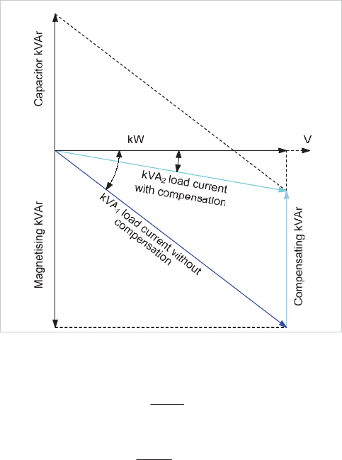
Shunt capacitors are often used to improve power factor. The
basis for compensation is shown in Figure 18.12, where
<
1
represents the uncorrected power factor angle and
<
2
the
angle relating to the desired power factor, after correction.
M
1
M
2
Figure 18.12: Power factor correction principle
The following may be deduced from this vector diagram:
Uncorrected power factor =
1
1
cos
M
kVA
kW
Corrected power factor =
2
2
cos
M
kVA
kW
Reduction in kVA = kVA
1
- kVA
2
If the kW load and uncorrected power factors are known, then
the capacitor rating in kvar to achieve a given degree of
correction may be calculated from:
Capacitor kVAr =
21
tantan
M
M
ukW
A spreadsheet can easily be constructed to calculate the
required amount of compensation to achieve a desired power
factor.
18.11.1 Capacitor Control
Where the plant load or the plant power factor varies
considerably, it is necessary to control the power factor
correction, since over-correction will result in excessive system
voltage and unnecessary losses. In a few industrial systems,
capacitors are switched in manually when required, but
automatic controllers are standard practice. A controller
provides automatic power factor correction, by comparing the
running power factor with the target value. Based on the
available groupings, an appropriate amount of capacitance is
switched in or out to maintain an optimum average power
factor. The controller is fitted with a ‘loss of voltage’ relay
element to ensure that all selected capacitors are disconnected
instantaneously if there is a supply voltage interruption. When
© 2011 Alstom Grid. Single copies of this document may be filed or printed for personal non-commercial use and must include this
copyright notice but may not be copied or displayed for commercial purposes without the prior written permission of Alstom Grid.
Chapter 18
Industrial and Commercial Power System Protection
18-13
the supply voltage is restored, the capacitors are reconnected
progressively as the plant starts up. To ensure that capacitor
groups degrade at roughly the same rate, the controller usually
rotates selection or randomly selects groups of the same size in
order to even out the connected time. The provision of
overvoltage protection to trip the capacitor bank is also
desirable in some applications. This would be to prevent a
severe system overvoltage if the power factor correction (PFC)
controller fails to take fast corrective action.
The design of PFC installations must recognise that many
industrial loads generate harmonic voltages, with the result
that the PFC capacitors may sink significant harmonic
currents. A harmonic study may be necessary to determine
the capacitor thermal ratings or whether series filters are
required.
18.11.2 Motor P.F. Correction
When dealing with power factor correction of motor loads,
group correction is not always the most economical method.
Some industrial consumers apply capacitors to selected motor
substations rather than applying all of the correction at the
main incoming substation busbars. Sometimes, power factor
correction may even be applied to individual motors, resulting
in optimum power factor being obtained under all conditions of
aggregate motor load. In some instances, better motor
starting may also result, from the improvement in the voltage
regulation due to the capacitor. Motor capacitors are often
six-terminal units, and a capacitor may be conveniently
connected directly across each motor phase winding.
Capacitor sizing is important, such that a leading power factor
does not occur under any load condition. If excess capacitance
is applied to a motor, it may be possible for self-excitation to
occur when the motor is switched off or suffers a supply
failure. This can result in the production of a high voltage or in
mechanical damage if there is a sudden restoration of supply.
Since most star/delta or auto-transformer starters other than
the ‘Korndorffer’ types involve a transitional break in supply, it
is generally recommended that the capacitor rating should not
exceed 85% of the motor magnetising reactive power.
18.11.3 Capacitor Protection
When considering protection for capacitors, allowance should
be made for the transient inrush current occurring on switch-
on, since this can reach peak values of around 20 times
normal current. Switchgear for use with capacitors is usually
de-rated considerably to allow for this. Inrush currents may be
limited by a resistor in series with each capacitor or bank of
capacitors.
Protection equipment is required to prevent rupture of the
capacitor due to an internal fault and also to protect the cables
and associated equipment from damage in case of a capacitor
failure. If fuse protection is contemplated for a three-phase
capacitor, HRC fuses should be employed with a current rating
of not less than 1.5 times the rated capacitor current.
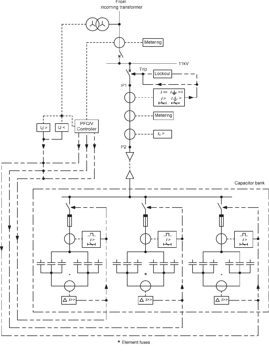
Medium voltage capacitor banks can be protected by the
scheme shown in Figure 18.14. Since harmonics increase
capacitor current, the relay will respond more correctly if it
does not have in-built tuning for harmonic rejection.
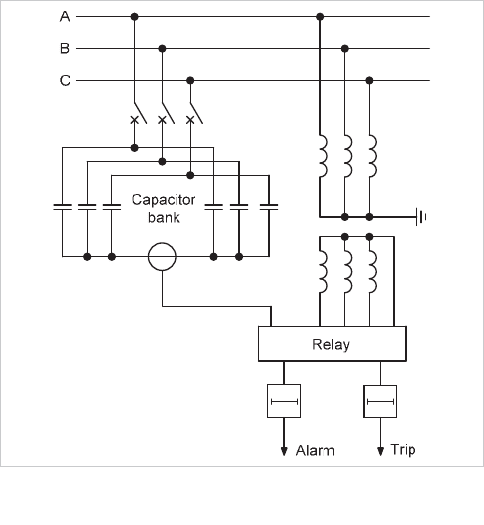
Double star capacitor banks are employed at medium voltage.
As shown in Figure 18.13, a current transformer in the inter
star-point connection can be used to drive a protection relay to
detect the out-of-balance currents that will flow when
capacitor elements become short-circuited or open-circuited.
The relay will have adjustable current settings, and it might
contain a bias circuit, fed from an external voltage transformer,
that can be adjusted to compensate for steady-state spill
current in the inter star-point connection.
Figure 18.13: Protection of double star capacitor banks
Some industrial loads such as arc furnaces involve large
inductive components and correction is often applied using
very large high voltage capacitors in various configurations.
Another high voltage capacitor configuration is the ‘split phase’
arrangement where the elements making up each phase of the
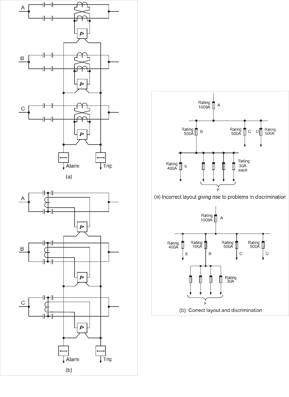
capacitor are split into two parallel paths. Figure 18.15 shows
two possible connection methods for the relay. A differential
relay can be applied with a current transformer for each
parallel branch. The relay compares the current in the split
phases, using sensitive current settings but also adjustable
compensation for the unbalance currents arising from initial
capacitor mismatch.
© 2011 Alstom Grid. Single copies of this document may be filed or printed for personal non-commercial use and must include this
copyright notice but may not be copied or displayed for commercial purposes without the prior written permission of Alstom Grid.
Network Protection & Automation Guide
18-14
Figure 18.14: Protection of capacitor banks
© 2011 Alstom Grid. Single copies of this document may be filed or printed for personal non-commercial use and must include this
copyright notice but may not be copied or displayed for commercial purposes without the prior written permission of Alstom Grid.
Chapter 18
Industrial and Commercial Power System Protection
18-15
Figure 18.15: Differential protection of split phase capacitor banks
18.12 EXAMPLES
In this section, examples of the topics dealt with in the Chapter
are considered.
18.12.1 Fuse Co-ordination
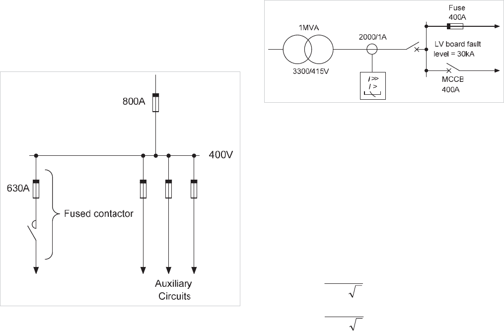
An example of the application of fuses is based on the
arrangement in Figure 18.16(a). This shows an unsatisfactory
scheme with commonly encountered shortcomings. It can be
seen that fuses B, C and D will discriminate with fuse A, but
the 400A sub-circuit fuse E may not discriminate, with the
500A sub-circuit fuse D at higher levels of fault current.
Figure 18.16: Fuse protection: effect of layout on discrimination
The solution, shown in Figure 18.16(b), is to feed the 400A
circuit
E
direct from the busbars. The sub-circuit fuse
D
may
now have its rating reduced from 500A to a value, of say
100A, appropriate to the remaining sub-circuit. This
arrangement now provides a discriminating fuse distribution
scheme satisfactory for an industrial system.
However, there are industrial applications where
© 2011 Alstom Grid. Single copies of this document may be filed or printed for personal non-commercial use and must include this
copyright notice but may not be copied or displayed for commercial purposes without the prior written permission of Alstom Grid.
Network Protection & Automation Guide
18-16
discrimination is a secondary factor. In the application shown
in Figure 18.17, a contactor having a fault rating of 20kA
controls the load in one sub-circuit. A fuse rating of 630A is
selected for the minor fuse in the contactor circuit to give
protection within the through-fault capacity of the contactor.
Figure 18.17: Example of back-up protection
The major fuse of 800A is chosen, as the minimum rating that
is greater than the total load current on the switchboard.
Discrimination between the two fuses is not obtained, as the
pre-arcing I
2
t of the 800A fuse is less than the total I
2
t of the
630A fuse. Therefore, the major fuse will blow as well as the
minor one, for most faults so that all other loads fed from the
switchboard will be lost. This may be acceptable in some
cases. In most cases, however, loss of the complete
switchboard for a fault on a single outgoing circuit will not be
acceptable, and the design will have to be revised.
18.12.2 Grading of Fuses/MCCBs/Overcurrent Relays
An example of an application involving a moulded case circuit
breaker, fuse and a protection relay is shown in Figure 18.18.
A 1MVA 3.3kV/400V transformer feeds the LV board via a
circuit breaker, which is equipped with an Alstom MiCOM
P14x numerical relay having a setting range of 8-400% of
rated current and fed from 2000/1A CTs.
Figure 18.18: Network diagram for protection co-ordination example -
fuse/MCCB/relay
Discrimination is required between the relay and both the fuse
and MCCB up to the 40kA fault rating of the board. To begin
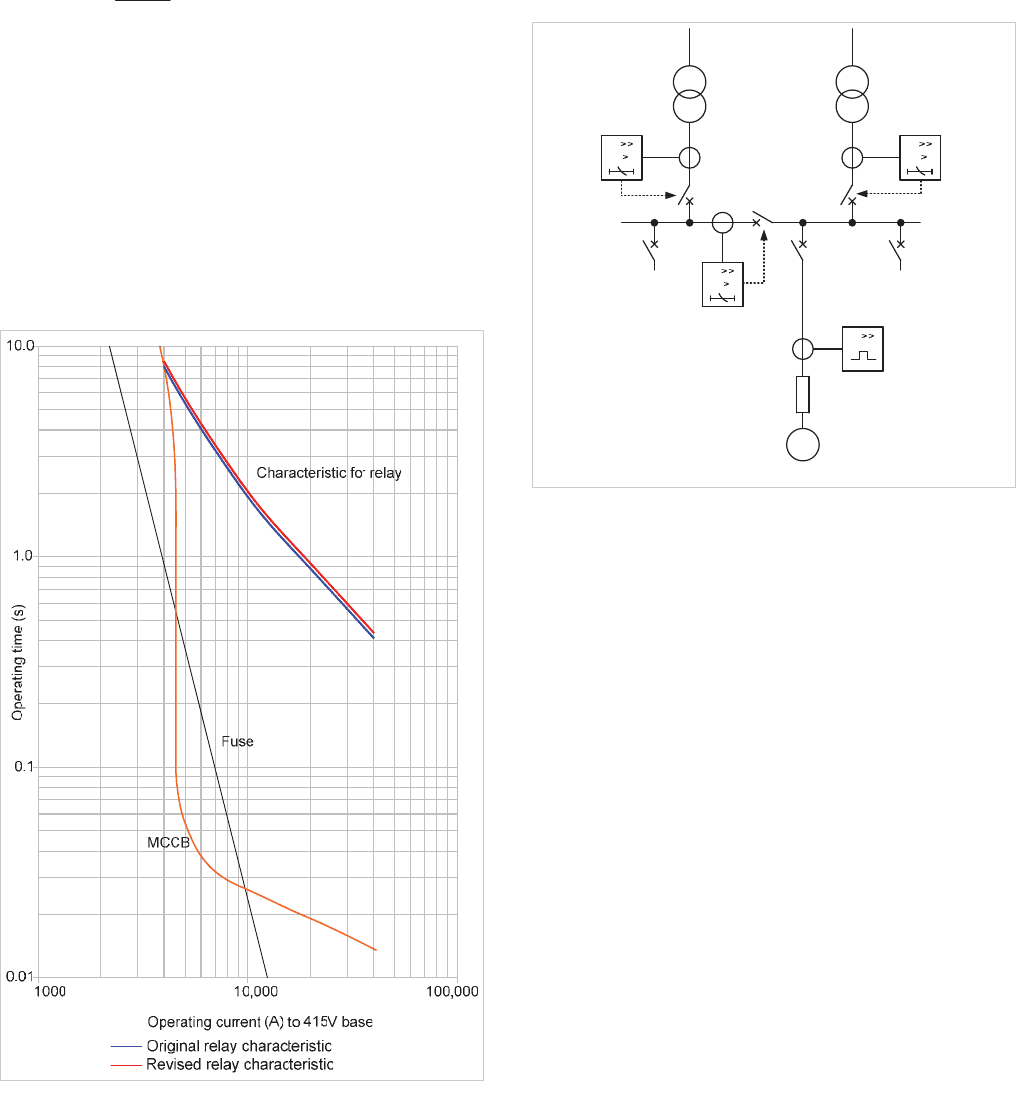
with, the time/current characteristics of both the 400A fuse
and the MCCB are plotted in Figure 18.19.
18.12.2.1 Determination of relay current setting
The relay current setting chosen must not be less than the full
load current level and must have enough margin to allow the
relay to reset with full load current flowing. The latter may be
determined from the transformer rating:
A
kV
kVA
1443
34.0
1000
3
FLC
u
u
With the CT ratio of 2000/1A and a relay reset ratio of 95% of
the nominal current setting, a current setting of at least 80%
would be satisfactory, to avoid tripping and/or failure to reset
with the transformer carrying full load current. However,
choice of a value at the lower end of this current setting range
would move the relay characteristic towards that of the MCCB
and discrimination may be lost at low fault currents. It is
therefore prudent to select initially a relay current setting of
100%.
18.12.2.2 Relay characteristic and time multiplier selection
An EI characteristic is selected for the relay to ensure
discrimination with the fuse (see Chapter 9 for details). From
Figure 18.19, it may be seen that at the fault level of 40kA the
fuse will operate in less than 0.01s and the MCCB operates in
approximately 0.014s. Using a fixed grading margin of 0.4s,
the required relay operating time becomes 0.4 + 0.014 =
0.414s. With a CT ratio of 2000/1A, a relay current setting of
100%, and a relay TMS setting of 1.0, the extremely inverse
curve gives a relay operating time of 0.2s at a fault current of
40kA. This is too fast to give adequate discrimination and
indicates that the EI curve is too severe for this application.
Turning to the VI relay characteristic, the relay operation time
is found to be 0.71s at a TMS of 1.0. To obtain the required
© 2011 Alstom Grid. Single copies of this document may be filed or printed for personal non-commercial use and must include this
copyright notice but may not be copied or displayed for commercial purposes without the prior written permission of Alstom Grid.
Chapter 18
Industrial and Commercial Power System Protection
18-17
relay operating time of 0.414s:
TMS setting =
583.0
71.0
414.0
Use a TMS of 0.6, nearest available setting.
The use of a different form of inverse time characteristic makes
it advisable to check discrimination at the lower current levels
also at this stage. At a fault current of 4kA, the relay will
operate in 8.1s, which does not give discrimination with the
MCCB. A relay operation time of 8.3s is required. To
overcome this, the relay characteristic needs to be moved
away from the MCCB characteristic, a change that may be
achieved by using a TMS of 0.625. The revised relay
characteristic is also shown in Figure 18.19.
Figure 18.19: Grading curves for Fuse/MCCB/relay grading example
18.12.3 Protection of a Dual-Fed Substation
As an example of how numerical protection relays can be used
in an industrial system, consider the typical large industrial
substation of Figure 18.20. Two 1.6MVA, 11/0.4kV
transformers feeding a busbar whose bus-section CB is
normally open. The LV system is solidly earthed. The largest
outgoing feeder is to a motor rated 160kW, 193kVA, and a
starting current of 7 x FLC.
I
I
Relay C
1
R
e
l
a
y
C
2
I
I
1.6 MVA
11/0.4kV
Z=6.25%
I
I
Relay B
M
I
Relay A
Motor cable
160kW
NO
A1
50kA rms
A2 0.4kV
Trip
Trip
Trip
2500/1
2500/1
2500/1
300/1
Figure 18.20: Relay grading example for dual-fed switchboard
The transformer impedance is to IEC standards. The LV
switchgear and bus bars are fault rated at 50kA rms. To
simplify the analysis, only the phase-fault LV protection is
considered.
18.12.3.1 General considerations
Analysis of many substations configured as in Figure 18.20
shows that the maximum fault level and feeder load current is
obtained with the bus-section circuit breaker closed and one of
the infeeding CBs open. This applies so long as the
switchboard has a significant amount of motor load. The
contribution of motor load to the fault level at the switchboard
is usually larger than that from a single infeeding transformer,
as the transformer restricts the amount of fault current infeed
from the primary side. The three-phase break fault level at the
switchboard under these conditions is assumed to be 40kA
rms.
Relays C are not required to have directional characteristics
(see Section 9.14.3) as all three circuit breakers are only closed
momentarily during transfer from a single infeeding
transformer to two infeeding transformers configuration. This
transfer is normally an automated sequence, and the chance of
a fault occurring during the short period (of the order of 1s)
when all three CBs are closed is taken to be negligibly small.
Similarly, although this configuration gives the largest fault
level at the switchboard, it is not considered from either a
switchboard fault rating or protection viewpoint.
It is assumed that modern numerical relays are used. For
© 2011 Alstom Grid. Single copies of this document may be filed or printed for personal non-commercial use and must include this
copyright notice but may not be copied or displayed for commercial purposes without the prior written permission of Alstom Grid.
Network Protection & Automation Guide
18-18
simplicity, a fixed grading margin of 0.3s is used.
18.12.3.2 Motor protection relay settings
From the motor characteristics given, the overcurrent relay
settings (Relay A) can be found using the guidelines set out in
Chapter 19 as:
Thermal element:
x current setting: 300A
x time constant: 20 mins
Instantaneous element:
x current setting: 2.32kA
These are the only settings relevant to the up
stream relays.
18.12.3.3 Relay B settings
Relay B settings are derived from consideration of the loading
and fault levels with the bus-section breaker between busbars
A1 and A2 closed. No information is given about the load split
between the two busbars, but it can be assumed in the
absence of definitive information that each busbar is capable of
supplying the total load of 1.6MVA. With fixed tap
transformers, the bus voltage may fall to 95% of nominal under
these conditions, leading to a load current of 2430A. The
IDMT current setting must be greater than this, to avoid relay
operation on normal load currents and (ideally) with aggregate
starting/re-acceleration currents. If the entire load on the
busbar was motor load, an aggregate starting current in excess
of 13kA would occur, but a current setting of this order would
be excessively high and lead to grading problems further
upstream. It is unlikely that the entire load is motor load
(though this does occur, especially where a supply voltage of
690V is chosen for motors – an increasingly common practice)
or that all motors are started simultaneously (but simultaneous
re-acceleration may well occur). What is essential is that relay
B does not issue a trip command under these circumstances –
i.e. the relay current/time characteristic is in excess of the
current/time characteristic of the worst-case starting/re-
acceleration condition. It is therefore assumed that 50% of the
total bus load is motor load, with an average starting current
of 600% of full load current (= 6930A), and that re-acceleration
takes 3s. A current setting of 3000A is therefore initially used.
The SI characteristic is used for grading the relay, as co-
ordination with fuses is not required. The TMS is required to
be set to grade with the thermal protection of relay A under
‘cold’ conditions, as this gives the longest operation time of
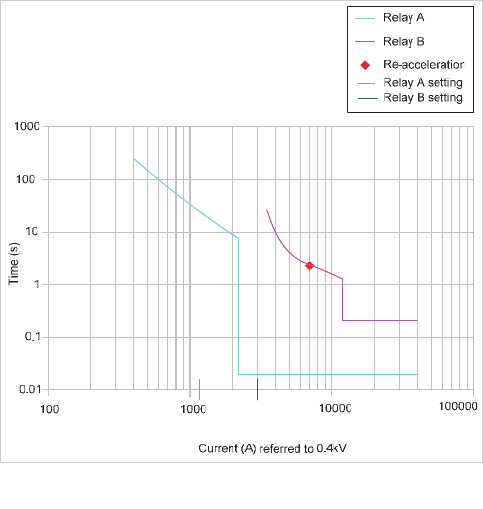
Relay A, and the re-acceleration conditions. A TMS value of
0.41 is found to provide satisfactory grading, being dictated by
the motor starting/re-acceleration transient. Adjustment of
both current and TMS settings may be required depending on
the exact re-acceleration conditions. Note that lower current
and TMS settings could be used if motor starting/re-
acceleration did not need to be considered.
The high-set setting needs to be above the full load current
and motor starting/re-acceleration transient current, but less
than the fault current by a suitable margin. A setting of
12.5kA is initially selected. A time delay of 0.3s has to used to
ensure grading with relay A at high fault current levels; both
relays A and B may see a current in excess of 25kA for faults
on the cable side of the CB feeding the 160kW motor. The
relay curves are shown in Figure 18.21.
Figure 18.21: Grading of relays A and B
18.12.3.4 Relays C settings
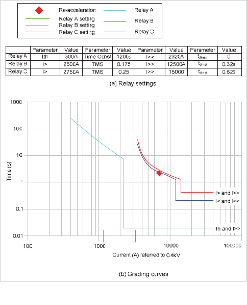
The setting of the IDMT element of relays C
1
and C
2
has to be
suitable for protecting the busbar while grading with relay B.
The limiting condition is grading with relay B, as this gives the
longest operation time for relays C.
The current setting has to be above that for relay B to achieve
full co-ordination, and a value of 3250A is suitable. The TMS
setting using the SI characteristic is chosen to grade with that
of relay B at a current of 12.5kA (relay B instantaneous
setting), and is found to be 0.45. The high-set element must
grade with that of relay B, so a time delay of 0.62sec is
required. The current setting must be higher than that of relay
B, so use a value of 15kA. The final relay grading curves and
settings are shown in Figure 18.22.
© 2011 Alstom Grid. Single copies of this document may be filed or printed for personal non-commercial use and must include this
copyright notice but may not be copied or displayed for commercial purposes without the prior written permission of Alstom Grid.
Chapter 18
Industrial and Commercial Power System Protection
18-19
Figure 18.22: Final relay grading curves
18.12.3.5 Comments on grading
While the above grading may appear satisfactory, the
protection on the primary side of the transformer has not been
considered. IDMT protection at this point will have to grade
with relays C and with the through-fault short-time withstand
curves of the transformer and cabling. This may result in
excessively long operation times. Even if the operation time at
the 11kV level is satisfactory, there is probably a Utility infeed
to consider, which will involve a further set of relays and
another stage of time grading, and the fault clearance time at
the Utility infeed will almost certainly be excessive. One
solution is to accept a total loss of supply to the 0.4kV bus
under conditions of a single infeed and bus section CB closed.
This is achieved by setting relays C such that grading with relay
B does not occur at all current levels, or omitting relay B from
the protection scheme. The argument for this is that network
operation policy is to ensure loss of supply to both sections of
the switchboard does not occur for single contingencies. As
single infeed operation is not normal, a contingency (whether
fault or maintenance) has already occurred, so that a further
fault causing total loss of supply to the switchboard through
tripping of one of relays B is a second contingency. Total loss
of supply is therefore acceptable. The alternative is to accept a
lack of discrimination at some point on the system, as already
noted in Chapter 9. Another solution is to employ partial
differential protection to remove the need for Relay A, but this
is seldom used. The strategy adopted will depend on the
individual circumstances.
18.13 REFERENCES
[18.1] Overcurrent Relay Co-ordination for Double Ended
Substations. George R Horcher. IEEE. Vol. 1A-14 No.
6 1978.
© 2011 Alstom Grid. Single copies of this document may be filed or printed for personal non-commercial use and must include this
copyright notice but may not be copied or displayed for commercial purposes without the prior written permission of Alstom Grid.
© 2011 Alstom Grid. Single copies of this document may be filed or printed for personal non-commercial use and must include this
copyright notice but may not be copied or displayed for commercial purposes without the prior written permission of Alstom Grid.
