ALSTOM T&D. Network Protection And Automation Guide (NPAG)
Подождите немного. Документ загружается.

Chapter 20 System Integrity Protection Schemes
20-5
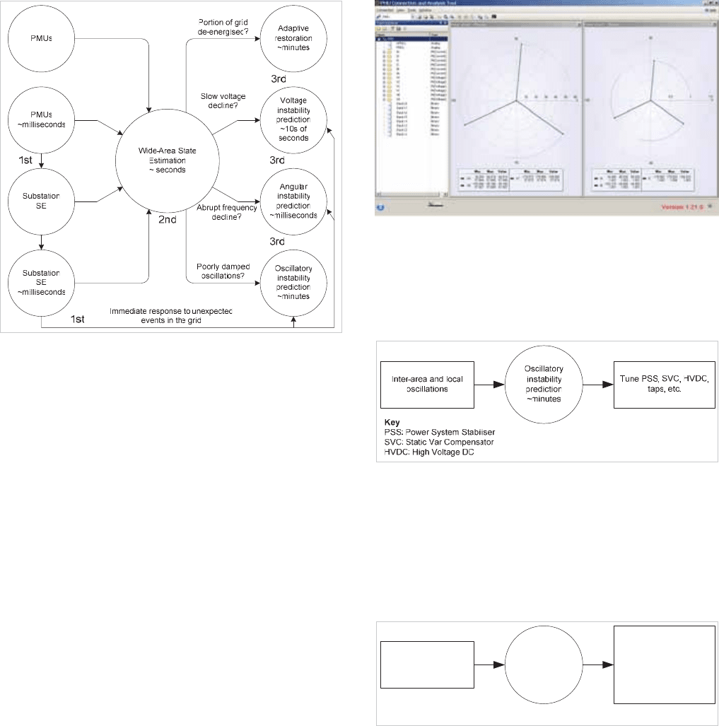
Figure 20.4: WAMPAC opportunities
Figure 20.4 shows applications based on the use of
synchrophasors and state estimation (SE) for oscillatory
stability, voltage stability, transient stability (or angular
instability prediction), and system restoration.
The technology can also offer event triggering based on
overcurrent, under/overvoltage, under/over-frequency and
under/over-rate of change of frequency.
20.3.1.1 Synchrophasors for Oscillatory Stability
Synchrophasors can be used for oscillatory stability detection
designed to detect slower inter-area system oscillations. These
are characterised by power oscillations between two areas of
generation, running at slightly different speeds and following
small system perturbations such as load switching or tap
changes. If there is insufficient system damping, these
oscillations do not die away and can escalate leading to
potential out-of-step conditions if no pre-emptive action is
taken. If the phasor measurement units feature frequency
tracking that can accurately measure and track small changes
in signal frequencies, this can provide an accurate
measurement for the fast detection of small signal oscillations
to initiate damping actions.
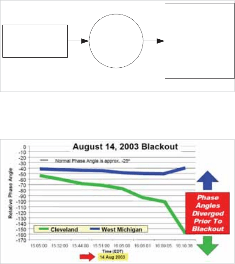
Figure 20.5: PMU data viewed in a simple visualisation tool
Synchronised measurements allow the comparison of the
phase of the oscillatory modes to determine the parts of the
system that are oscillating with respect to each other, and
enable stabilising actions to be initiated as shown in Figure
20.6.
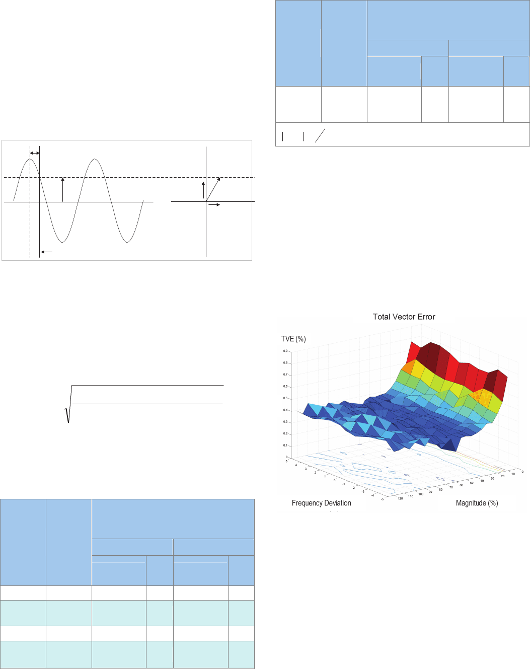
Figure 20.6: Oscillatory instability prediction
20.3.1.2 Synchrophasors for Voltage Stability
Synchrophasors can be used to predict voltage instability. By
comparing voltage and power transfers on the line against
specific stability margins, operators can be alerted to slow
voltage declines and take remedial actions such as switching in
reactors as shown in Figure 20.7.
Voltage
instability
prediction
~10s of
seconds
Slow voltage decline
or load level?
Capacitor switching
Reactor switching
SVC setting
Undervoltage shedding
Remedial actions
Fast unit runback
Key
SVC: Static Var Compensator
Figure 20.7: Voltage instability prediction
20.3.1.3 Synchrophasors for Transient Stability
Synchrophasors can be used to defend transient stability by
predicting angular instability. By being measured in real-time
rather than estimated, generator and bus-phase angles can be
compared and stability threats can be presented to an operator
for remedial action such as controlled islanding as shown in
Figure 20.8.
© 2011 Alstom Grid. Single copies of this document may be filed or printed for personal non-commercial use and must include this
copyright notice but may not be copied or displayed for commercial purposes without the prior written permission of Alstom Grid.
Network Protection & Automation Guide
20-6
Angular
instability
prediction
~milliseconds
Frequency decline
Controlled islanding
Generator tripping
Dynamic braking
Underfrequency.
shedding
Fast load shedding
FACTS, HVDC controls
Remedial actions
Special protection
Fast unit runback
Key
FACTS: Flexible AC Transmission System
HVDC: High Voltage DC
Figure 20.8: Angle instability prediction
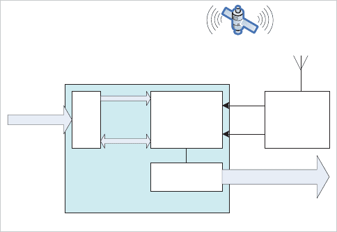
Figure 20.9 shows the relative phase angles from two parts of
the North American grid taken on August 14th 2003.
Figure 20.9: Phase angle divergence prior to blackout
The phase angles from the two parts of the system can be seen
diverging. A major blackout followed. This is the type of event
that the synchrophasor technology can help prevent. But what
exactly is a synchrophasor?
20.3.2 Synchronised Phasor Measurements
A phasor is a representation of a sinusoidal quantity,
representing the sinusoid as a vector rotating on the complex
plane, defined in terms of amplitude and phase. As steady
state power system quantities are sinusoids, it follows that
they can be represented by phasors. When augmented by an
accurate time synchronisation signal, time synchronised
phasors, known as synchrophasors can be produced. The
potential benefits of synchrophasor technology have long been
recognised, but it is only since enabling technologies have
developed that their effective application became reality.
In 1893, Charles Proteus Steinmetz presented a paper on a
simplified mathematical description of the waveforms of
alternating electricity. Steinmetz called his representation a
phasor, and phasor notation became widely used in the field of
electrical power systems (see section 3.4.1). The time
synchronisation of phasors in what were to become known as
phasor measurement units evolved and in 1988 the first
phasor measurement units based on Steinmetz’s technique,
were developed. The first commercial phasor measurement
unit was launched in 1992.
The deployment of phasor measurement units into electrical
power systems, however, was limited initially as two main
issues could not be addressed:
x Accuracy of time synchronisation
x Cost effective, high-speed, communications
With the global positioning satellite system, the ability to time
synchronise anywhere in the world to an
accuracy of better
than a micro-second is achievable. Developments in the
telecommunication markets have brought fast Ethernet to the
substation, and with these developments, the hurdles are
overcome, and the potential of synchrophasors can be
exploited to the maximum.
20.3.3 Synchrophasor Definition
A phasor is a vector representation on the complex plane of a
sinusoidal quantity such as an alternating current.
A synchrophasor is a phasor calculated from sampled values
that are referenced to a common timing signal. The timing
signal is global, meaning that a synchrophasor measured
anywhere in the world will be referenced to the same time
signal. This enables synchrophasors to be communicated for
collation and comparison. This is the fundamental concept
behind wide-area special protection schemes.
The IEEE 1344 standard for synchrophasors was published in
1995. It was reaffirmed in 2001, but in 2005 it was
superseded by IEEE C37.118. This recognised the
developments that would facilitate the effective application of
synchrophasors to electrical power systems. IEEE C37.118
describes the standards for measurement of synchrophasors,
the method of quantifying the measurements, as well as the
testing and certification requirements for verifying accuracy. It
also prescribes the data transmission format and protocol for
synchrophasor communication.
The standard prescribes that all measurements are referenced
to an accurate one pulse per second (1pps) signal. Generally it
is anticipated that this will be derived from the global
positioning satellite system, but it can be from any external
source provided the accuracy is in accordance with the
requirements.
Phasor representation defines the complex exponential as a
point or vector on the complex plane according to the
equation:
TT
T
sinjcose
j
The IEEE C37.118 standard specifies that the angle is zero
degrees when the maximum of the signal to be measured
coincides with the leading edge of GPS 1pps pulse. It follows
that it will be –/2 radians (-90 degrees) if the positive zero
crossing coincides with the 1pps pulse, +/2 radians (+90
© 2011 Alstom Grid. Single copies of this document may be filed or printed for personal non-commercial use and must include this
copyright notice but may not be copied or displayed for commercial purposes without the prior written permission of Alstom Grid.
Chapter 20 System Integrity Protection Schemes
20-7
degrees) if the negative zero crossing coincides with the 1pps
pulse, and π radians (180 degrees) when the reverse polarity
peak of the signal to be measured coincides with the 1pps
pulse.
The relationship of time domain and frequency domain signals
relative to the 1pps signal is further described in Figure 20.10,
where
)(nX
r
and )(nX
i
are the RMS real and imaginary
filtered components at a particular instance and θ is the phase
angle as per the IEEE C37.118 standard definition.
1 PPS
Peak
θ
ms
θ
Xi(n)
Xr(n)
Figure 20.10: Time and frequency domain representation of
synchrophasors
The measured angle θ is valid in the range of –π to +π
radians.
A primary requirement for synchrophasors is the accuracy of
the measured phasor. The IEEE C37.118 standard defines the
total permitted vector error (TVE) for the static condition at
nominal frequency as:
22
22
ir
XX
X)n(XX)n(X
TVE
iirr
Where
X
r
(n) and X
i
(n) are the measured real and imaginary
components and
X
r
and X
i
are the reference values.
Levels of accuracy are specified for the permissible total vector
error as shown in Table 20.1 .
Range of influence quantity change with respect
to reference and maximum allowable TVE (in %)
for each compliance level
Level 0 Level 1
Influence
quantity
Reference
Condition
Range
TVE
(%)
Range
TVE
(%)
Signal frequency
F
nominal
+/- 0.5Hz 1 +/- 5Hz 1
Signal
magnitude
100% rated 80% -120% rated 1 10% -120% rated 1
Phase angle 0 radians +/-π radians 1 +/-π radians 1
Harmonic
distortion
<0.2%
(THD)
1%, any harmonic
up to 50th
1
1%, any harmonic
up to 50th
1
Range of influence quantity change with respect
to reference and maximum allowable TVE (in %)
for each compliance level
Level 0 Level 1
Influence
quantity
Reference
Condition
Range
TVE
(%)
Range
TVE
(%)
Out-of-band
interfering signal
at freq f
i
*
<0.2% of input
signal
magnitude
1% of input signal
magnitude
1
1% of input signal
magnitude
1
*
2
0
s
i
F
ff
, where
F
s
= phasor reporting rate and
f
0
=
F
nominal
Table 20.1: Influencing quantities and allowable error limits for
compliance levels 0 – 1.
Devices offering compliance level 1 perform better in SIPS
schemes, whereas level 0 devices are intended more for
measurement purposes.
This measurement accuracy will vary with the magnitude and
frequency of the input signal and may be depicted graphically
as shown in Figure 20.11. The graph depicts a device with a
total vector error typically less than 0.4% (y-axis), consistent for
system frequency excursions off-nominal (z-axis), and
maintained for all except very low current magnitudes (x-axis).
Figure 20.11: Graphical representation of synchrophasor total vector
error
20.3.4 Synchrophasor Communication
As well as the generation of synchrophasors, the IEEE C37.118
standard also defines how the synchrophasor values are to be
communicated.
Whilst the standard does not mandate that Ethernet
communications are used for synchrophasor transmission, it is
Ethernet that often enables wide-area phasor measurement
technology, and that is reflected in this section. Some
knowledge of Ethernet communications is assumed here, but if
needed, a more detailed discussion on substation
© 2011 Alstom Grid. Single copies of this document may be filed or printed for personal non-commercial use and must include this
copyright notice but may not be copied or displayed for commercial purposes without the prior written permission of Alstom Grid.

Network Protection & Automation Guide
20-8
communications, including Ethernet, is presented in chapter
24: ‘The Digital Substation’.
Four message types associated with synchrophasor
communications are described in the standard:
x Data
x Configuration
x Header
x Command
All message types have a similar frame structure to package
the information.
The “Configuration”, “Header” and
“Command” types are used to set up the communications and
are used infrequently. The “Data” type is used for the real-
time transfer of synchrophasor values, and that will have the
largest impact on the communications system.
According to the standard, synchrophasor signals are
encapsulated into data packets, or frames, for transmission
across, say, an Ethernet network. An example of a typical data
frame is shown in Table 20.2.
Field function Field size (bytes)
Message synchronisation 2
Frame size definition 2
PMU ID code* 2
Real time timing information 8
Status information 2
Phasor data values Typically 48
System frequency measurement 2
Rate of change of system frequency 2
Digital data values 2
Frame checksum 2
Total Typically 72
Table 20.2: Synchrophasor data frame format
* The PMU ID code is set to uniquely associate the
synchrophasor values to the PMU responsible for producing
them.
The rate at which the frames are sent is defined.
x For 50Hz operation the frame repetition rate can be set
to 10, 25 or 50 frames per second
x For 60Hz operation the frame repetition rate can be set
to 10, 12, 15, 20, 30, or 60 frames per second.
The faster the rate of frame repetition, the shorter the latency
in responding to a developing system condition, allowing fa
ster
SIPS and state estimation reaction.
Clearly the more times per second that the data is sent, the
greater the impact on the Ethernet communications.
20.3.4.1 Mapping Synchrophasors to Ethernet
When mapped to Ethernet the synchrophasor phasor data
frames can use either transmission control protocol (TCP) or
user datagram protocol (UDP) according to preference. TCP is
a connection-oriented protocol. It manages message
acknowledgement, re-transmission and time out. As such it
can be considered to be reliable and ordered, but carrying
overheads. UDP is a simpler protocol that broadcasts
messages from the transmitter without checking the state of
the receiver. As such it can be considered less reliable and not
ordered, but lean. The choice will come down to the specific
requirements of the application.
The TCP or UDP mapped messages are written to and read
from using standard internet protocol (IP) input-output
functions. These functions apply a numerical identifier for the
data structures of the terminals of the communications. The
terminal is referred to as a port and the numerical identifier is
called the port number. The port number should be set to
align with the recipient phasor data concentrator (see section
20.3.7).
Other settings that apply as the phasor message is mapped to
the Ethernet layer are the IP address, subnet mask, and
gateway address.
20.3.4.2 Communication Bandwidth Requirements
It can be useful to understand how much loading the addition
of a phasor measurement unit can have on a communications
system. A typical frame length of 72 bytes has already been
mentioned. For a typical application with a frame length of 72
bytes and a repetition rate of 60 per second, the minimum
bandwidth requirement for these raw frames is, therefore,
4320 bytes per second.
Ethernet conforms to the OSI (Open System Interconnect) 7
layer model (covered in chapter 24). Some layers require extra
information to be added and so, in addition to the raw data
frames, there is an overhead associated with the OSI 7-layer
model.
For TCP/IP mapping the overhead is:
x TCP 24 bytes per frame
x IP 20 bytes per frame
x MAC 18 bytes per frame
So the TCP/IP overhead is 62 bytes of data per frame.
For UDP/IP mapping the overhead is:
x Source port 2 bytes
x Destination Port 2 bytes
x UDP length 2 bytes
© 2011 Alstom Grid. Single copies of this document may be filed or printed for personal non-commercial use and must include this
copyright notice but may not be copied or displayed for commercial purposes without the prior written permission of Alstom Grid.
Chapter 20 System Integrity Protection Schemes
20-9
x UDP checksum 2 bytes
x IP 20 bytes per frame
So the UDP/IP overhead is 28 bytes of data per frame.
As the C37.118 frame contains 72 bytes, the total number of
bytes per frame is 134 for TCP and 100 for
UDP.
With 8 bits per byte, the resulting bandwidth of the maximum
frame rate is thus:
x 1072 * 50 = 53.6kbps for a maximum frame rate of 50
frames per second (TCP)
x 1072 * 60 = 64.32kbps for a
maximum frame rate of
60 frames per second (TCP)
x 800 * 50 = 40kbps for a maximum frame rate of 50
frames per second (UDP)
x 800 * 60 = 48kbps for a maximum frame rate of 60
frames per second (UDP)
These figures
are not absolute, but they can be of benefit in
planning network requirements when installing and operating
phasor measurement units.
20.3.5 Phasor Measurement Units
Synchrophasors are generated in phasor measurement units.
A typical phasor measurement unit architecture is shown in
Figure 20.12.
Ethernet
processor
GPS
Receiver
Protection and
measurement
processors
Data frames over
serial or Ethernet
(TCP/UDP)
A/D
Digitised
samples
Analogue
electrical
signals
1 PPS
IRIG-B
IEEE C37.118 data
PMU
Figure 20.12: Typical Phasor measurement unit architecture
Electrical signals to be converted into synchrophasors are
presented at the analogue inputs. They are sampled and
converted into numerical values in an analogue to digital
converter (A/D). The sampling is controlled by the
measurement processor which is synchronised to the GPS
system by a 1pps signal from a time synchronisation unit. The
numerical values representing the digitised samples are passed
to the measurement processor. The measurement processor
determines the amplitude and phase quantities required for the
synchrophasors according to their displacement from the 1pps
signal. The measurement processor also calculates the derived
quantities that are required to be presented as synchrophasors.
These include sequence components, frequency, and rate-of-
change of frequency, etc.
An IRIG-B signal from the time synchronisation unit allows the
measurement processor to accurately time-stamp the
synchrophasor values before passing them to the Ethernet
processor. The Ethernet processor frames the synchrophasor
values according to IEEE C37.118 before transmitting over
either TCP/IP or UDP/IP.
20.3.5.1 Physical Deployment of Phasor
Measurement Units
There is no need to install phasor measurement units at every
bus on the system as this will not necessarily contribute to
more efficient system operation. Indeed, too many phasor
measurement units could cause congestion on the
communications system, making data less manageable.
Phasor measurement units should be connected so that inter-
area oscillations and other critical dynamics will be correctly
monitored. They should be deployed on the network at critical
buses to ensure that a sufficient picture of the system
dynamics is available to the control centre to enable decisions
to be made. System visualisation using synchrophasors from
various parts of the system can show, for example, the
angular, frequency and voltage differences between groups of
generators. To do this, synchrophasors from various locations
need to be brought together, and one method of achieving this
is by means of phasor data concentrators, which is covered in
section 20.3.7.
20.3.6 Time Synchronisation
Phasor measurement units require accurate time
synchronisation.
IEEE-1588 describes a high-precision time protocol that can
achieve sub-microsecond accuracy for time synchronisation to
be used in measurement systems. It is an Ethernet protocol
that can be connected to a local area network (LAN). Timing
is derived from the global positioning satellite (GPS) system.
Since the synchronism is delivered by the Ethernet LAN, only
one GPS receiver is required to synchronise all devices on the
LAN. This offers potential cost benefits when compared to
using dedicated time synchronisation devices, especially as the
PMUs are typically connected to the Ethernet for the
transmission of synchrophasors. Given the criticality of
delivering the time synchronisation signal, however, it may be
more conservative to apply dedicated time synchronisation
devices into the substation using connections that are separate
to the LAN. A typical time synchronisation device might
© 2011 Alstom Grid. Single copies of this document may be filed or printed for personal non-commercial use and must include this
copyright notice but may not be copied or displayed for commercial purposes without the prior written permission of Alstom Grid.
Network Protection & Automation Guide
20-10
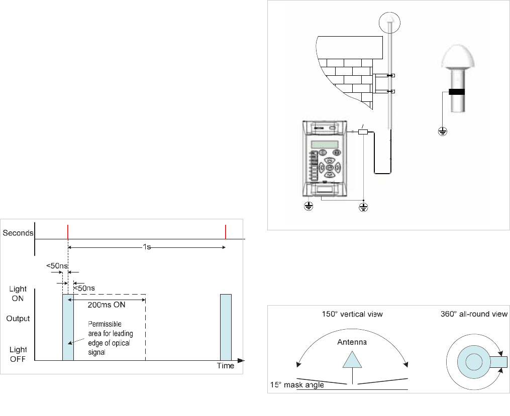
provide a one-pulse-per-second (1pps) signal, derived from
the GPS signals, in order to provide precise alignment of the
synchrophasors. To combat the effects of electrical
interference in the substation environment, the 1pps signal is
generally presented as a fibre-optic signal. The accuracy is
typically better than 0.1s. Although the 1pps signal is very
accurate (Figure 20.13), the pulse on it only signifies that
another second has passed (or is about to start). In order that
the phasor measurement unit can provide an accurate time
stamp for the synchrophasors, it is necessary to provide an
additional ‘real’ time signal. This is achieved with an IRIG-B
output, which delivers coordinated universal time (UTC) for
very accurate time stamping. It is quite likely that the time
synchronisation device will feature multiple outputs and be
capable of synchronising multiple PMUs and merging units,
providing substation-wide timing information.
Figure 20.13: 1pps accuracy
The GPS system consists of more than 20 satellites rotating in
orbit above the earth. The satellites are not in geo-stationary
orbit, and so the constellation that can be ‘seen’ is constantly
changing. In general, up to 7 satellites can be ‘seen’ at any
time. When GPS time synchronising receivers are energised,
they need to initialise their timing algorithms. Generally, this
requires that at least 4 satellites are in view for a short while.
In order to receive the signals from the GPS satellites, an
antenna is required. This needs to be mounted externally. A
mounting pole is generally used as shown Figure 20.14.
Mounting pole / mast
is to be earthed to
ma in building earth
Note
Earth cable to be <=10m
Earth cable to be 10mm
Lightning
arrester
See note
See detail
See note
See note
Figure 20.14: Antenna connection details
It is vital that the receiving antenna has the best possible
mounting location to maintain reception with as many
satellites as possible, thus the ideal mounting is shown in
Figure 20.15.
Figure 20.15: GPS antenna required line of sight
The antenna should be mounted so that it is above the roofline
of the building to which it is attached, ensuring that there is a
360º horizontal view and a 150º vertical view of the sky (a
masking angle of 15º with respect to the horizon is the
maximum that should be permitted). Ideally there should be
no obstructions in view such as metal structures or buildings.
If the masking angle is greater than 15º with respect to the
horizon (i.e. if is a large obstruction) the antenna must be re-
sited or mounted on a longer antenna pole.
Due to the requirement for ensuring such a clear view of the
GPS constellation, the antenna is likely to be the highest
component in the vicinity. As such it is exposed to lightning,
and suitable protection is required. A lightning arrestor is
recommended for protection.
20.3.7 Phasor Data Concentrators
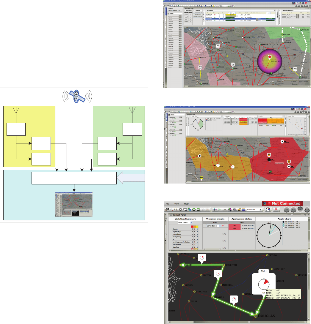
As shown in Figure 20.16, a phasor network consists of phasor
measurement units (PMU) dispersed throughout the electricity
system and connected to an energy management system via
© 2011 Alstom Grid. Single copies of this document may be filed or printed for personal non-commercial use and must include this
copyright notice but may not be copied or displayed for commercial purposes without the prior written permission of Alstom Grid.
Chapter 20 System Integrity Protection Schemes
20-11
phasor data concentrators (PDC). Phasor data concentrators
are devices which collect data from a number of phasor
measurement units. They convert such data into a single data
stream for onward transmission. Phasor measurement units
are connected to a phasor data concentrator at either the
substation or the control centre level.
Phasor data concentrators connect to supervisory control and
data acquisition (SCADA) systems and/or energy management
systems (EMS) at the central control facility to provide the
synchrophasor information for the wide-area applications.
PMU
PDC
GPS
Receiver
GPS
Receiver
PMU
Visualisation
Software
PMU
PMU
Substation A Substation B
From other
substations
Figure 20.16: PMU and PDC architecture
The complete network requires rapid transfer of data within
the frequency of sampling of the synchrophasor data.
The phasor data concentrator correlates the data, and controls
and monitors the phasor measurement units. It also serves to
archive the data, which is essential in the event that post-
disturbance analysis might be undertaken in order to
determine the root causes of cascade events. At the central
control facility, the SCADA/EMS system presents system-wide
data on all generators and substations in the system with
frequent regular updates. These updates provide for a
visualisation of the system which facilitates response-based
schemes.
20.3.8 System Visualisation
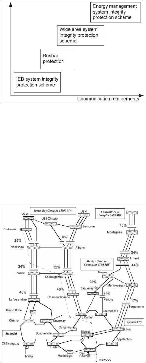
System visualisation enhances wide-area schemes. Figure
20.17, Figure 20.18, and Figure 20.19, show visualisations of
electrical networks as presented on an advanced energy
management system.
Figure 20.17: Stability state: annunciating voltage contours, weak
elements and possible remedial actions
Figure 20.18: Visualisation of inter-area oscillations: frequency,
severity and damping
Figure 20.19: Angular separation across transmission lines: alerts to
dispatchers
The figures show how phasor measurement units are providing
EMS software with synchrophasor values and how virtual
phase-meters connected to the lines give a clear picture of the
real-time phase differences between buses. If the angular
displacement exceeds a preset value, dispatchers are informed
of the violation and the options available to them for remedial
action.
System visualisation of real-time data realised thanks to wide-
© 2011 Alstom Grid. Single copies of this document may be filed or printed for personal non-commercial use and must include this
copyright notice but may not be copied or displayed for commercial purposes without the prior written permission of Alstom Grid.
Network Protection & Automation Guide
20-12
area technology provides power system operators greater
awareness, and hence more precise control of the system.
Underpinning this wide-area technology is the capability to
accurately time synchronise the phasor measurement units.
20.4 NON-SYNCHRONISED SYSTEM
INTEGRITY PROTECTION SCHEMES
The system integrity protection schemes described in the
previous section require highly accurate time synchronisation
and fast communications infrastructure. One might be
tempted to consider that system integrity protection can only
be afforded where these facilities are available. This is not,
however, the case.
The numerical busbar protection outlined in chapter 15 can be
considered as a distributed protection scheme as information is
gathered from peripheral units at various points on the system
for transmission to a central unit where protection monitoring
and control is managed. This shows how distributed
intelligence can work, and by increasing the geographical
spread of other suitable devices, wide-area schemes are the
next logical step.
Recognising however that sometimes information is available
only from a single point in the system, system integrity
protection schemes have been developed that require neither
communications, nor accurate time synchronisation.
By taking signal inputs from single points in the power system,
and by using special filters and techniques such as fuzzy logic,
predictive out-of-step or loss of synchronism conditions can be
detected and consequently acted upon to maintain system
stability. Similar techniques can be used to detect and act on
changes to system topology such as loss of power corridor.
By adding in busbar protection and relabeling the horizontal
axis in Figure 20.2 , the communication requirement of system
integrity protection can be highlighted, as shown in Figure
20.20.
Local Centralised
Figure 20.20: Communications requirements for system integrity
protection schemes.
This shows ‘local’ IED system integrity protection schemes that
do not require any communications, and these form the
subject of the rest of this chapter.
20.4.1 Single-point special protection
In countries where large sources of power generation are
geographically far from the principal loads, so-called
transmission corridors of power provide the routes for the
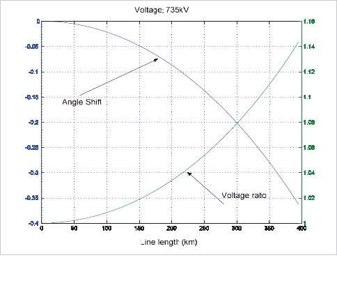
transmission of that power. One example of this is the Hydro-
Québec network in Canada as shown in Figure 20.21.
Figure 20.21: Hydro-Quebec 735kV series-compensated transmission
system (reproduced courtesy of Hydro-Quebec)
Reliability of transmission of power on such systems can be
achieved by the addition of series compensation and shunt
reactors, but these bring added complexity. Protection against
system disturbances may be provided to some extent by
© 2011 Alstom Grid. Single copies of this document may be filed or printed for personal non-commercial use and must include this
copyright notice but may not be copied or displayed for commercial purposes without the prior written permission of Alstom Grid.
Chapter 20 System Integrity Protection Schemes
20-13
frequency relays or voltage relays set to initiate actions such as
load-shedding on under-frequency conditions, but these may
not be sufficient in themselves for all applications and
sophisticated system integrity protection schemes have been
developed to complement them. Two particular examples that
do not require communications are described in sections
entitled 20.4.2 System Topology Changes and 20.4.3 System
Synchronism S
tability. The former describes an example of an
event-based system integrity protection scheme looking for
changes in system topology. The latter describes an example of
a response-based system integrity protection scheme looking
for system instability.
Both of these system integrity protection schemes are able to
anticipate system-threatening conditions using local variables
only. They are based on Kalman filters and fuzzy-logic multi-
criteria algorithms. These system integrity protection schemes
are applicable to large power systems prone to transient and
dynamic instabilities.
20.4.2 System Topology Changes
Detecting topology changes such as open line conditions
allows timely initiation of system defence plans for severe
contingencies such as a loss of transmission corridor. In the
absence of communications, signalling an open line condition
from a remote terminal is not possible and so, detecting a loss
of corridor caused by a remote terminal action using only
locally available signals can enable system stabilising actions
to be initiated.
20.4.2.1 Open Line Detection
Open line detection, like any other protection, needs to be
secure, reliable, and sufficiently fast.
To be secure, the detector should not operate in cases of low or
zero power transfer on the monitored line, distortion on line
voltages and currents during faults, fast variations in the
power flow, reversal of the power flow, power swings, sub-
synchronous resonances resulting from the parallel
combination of shunt reactors and series capacitors, nor
should it operate in the presence of harmonics.
To be reliable, the detector should detect line opening at the
remote end, line closing at the local end when already open at
the remote end, and line closing or opening with a shunt
reactor connected.
The typical speed required for open line detection operation is
two cycles or less.
As with many other aspects of electrical power systems, open
line operation can be characterised by both transient and
steady state conditions. Observation of the transient state
aspects and steady state aspects of open line conditions
reveals that transient events generally are associated with line
opening, whilst steady state phenomena are more closely
linked to closed lines.
An open line condition is very similar to a closed line which has
no active power transfer. If the relationship of critical
measured variables such as the voltage and the reactive power
are observed when the active power of a connected line
disappears, certain characteristics become apparent. Figure
20.22 shows that, for a given line length, an operating point
(consisting of the angle shift and the voltage ratio between its
ends) can be found so that, as seen from the sending end,
both active and reactive powers disappear.
Angle shift for zero Ps and Qs (degrees)
Voltage ratio zero Ps and Qs
Figure 20.22: Voltage ratio and angle trajectories vary with line length
for sending end active (Ps) and reactive (Qs) powers both at zero.
Although this critical operating point can be calculated, it is
very sensitive: For short lines, say 30km, the typical
sensitivities are 45% MW per degree of angle shift and 25%
MVAr per unit of voltage ratio.
It is therefore difficult to accurately detect this condition based
on power or current measurement alone, and thus it cannot
form a reliable basis for detecting open lines.
Studying the transient state aspects of opening a line provides
a better basis for open line detection. Observing the rate of
change of active and reactive power for various system events
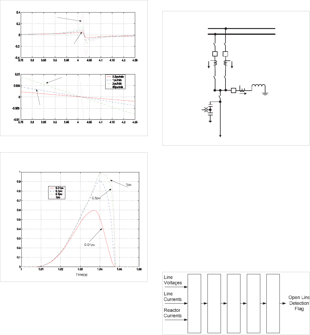
produces interesting results. The rate of change of power
(dP/dt, or DeltaP) can be studied for various system events
and two in particular are illustrated in Figure 20.23 and Figure
20.24.
© 2011 Alstom Grid. Single copies of this document may be filed or printed for personal non-commercial use and must include this
copyright notice but may not be copied or displayed for commercial purposes without the prior written permission of Alstom Grid.
Network Protection & Automation Guide
20-14
DeltaP
P Ramp
Time(s)
2pu/min
1pu/min
60pu/min
0.5pu/min
Figure 20.23: Rate of change of power (DeltaP) filter response to
power flow reversal
DeltaP
Figure 20.24: Rate of change of power (DeltaP) at breaker opening
Figure 20.23 shows power transfer ramping from a positive
direction to a negative direction, thus passing through zero
without apparently any significant effect. As the power ramp
crosses zero, however, it can be seen that DeltaP reaches a
maximum value a few cycles later. Although the maximum
value of DeltaP varies according to the power slope, the
maximum is reached at nearly the same time.
Figure 20.24 shows the effect on DeltaP of suddenly opening a
line at various values of surge impedance loading. In all cases,
when the line is opened, DeltaP increases sharply from its zero
steady-state value to its maximum value.
It is apparent that observing DeltaP provides the capability for
fast reliable detection of line opening.
20.4.2.2 Implementing Open Line Detection
D
D
D
SUBSTATION
BUSBARS
CVT
LINE BREAKERS
SHUNT REACTOR
v
ICT1
v
ICT2
IREACTOR
CT1 CT2
LINE
CT3
LINE
DISCONNECTOR
Figure 20.25: Connections for open line detection.
Figure 20.25 shows typical inputs used by an open line
detection algorithm. The inputs are taken from a capacitive
voltage transformer (CVT) and three sets of current
transformers (CT1, CT2 associated with the circuit breakers
and CT3 associated with the shunt reactor).
The functional diagram of the open line detection is shown in
Figure 20.26. It consists of five principal elements.
x Anti-alias filtering
x Kalman filtering
x Pre-processing
x Fuzzy logic
x Output logic
Fuzzy Logic Engine
Output logic
Anti-alias filter
Kalman filters
Open Line Detection Pre-
processor
Figure 20.26: Open-line detection functional block diagram
Anti-aliasing filters limit the bandwidth of the input signals
before high speed data acquisition converts the input signals
into numeric values for provision to the principal filtering unit.
The signals are filtered to extract the fundamental phasor
components.
These vectors are used as the inputs into a Kalman Filter. A
Kalman Filter is used since it can extract the fundamental
© 2011 Alstom Grid. Single copies of this document may be filed or printed for personal non-commercial use and must include this
copyright notice but may not be copied or displayed for commercial purposes without the prior written permission of Alstom Grid.
