Xin Q. Diesel Engine System Design
Подождите немного. Документ загружается.

710 Diesel engine system design
© Woodhead Publishing Limited, 2011
heat generated per unit volume of the lubricant is proportional to the product
of oil viscosity and the square of bearing shear rate. Thinner oil lms generate
a higher shear rate and a larger amount of viscous heat. In a component-level
analysis, the energy equation may be introduced along with the true mass-
conserving cavitation condition to conduct a coupled thermohydrodynamic
lubrication analysis in order to predict the oil temperature and the viscosity
variation. However, for engine system-level estimation, a fast and simpli ed
approach is preferred to estimate the operating oil temperature in the bearing.
Spearot et al. (1989) found that the effective temperature of the oil in the
bearing is generally higher than that in the sump. To estimate the bearing
operating oil temperature, an empirical formula was provided as a function
of sump oil temperature, oil viscosity, minimum oil lm thickness, engine
rotational speed, and brake torque.
10.6.2 Engine bearing friction calculation
Assuming the journal has no eccentricity within the bearing and the
circumferential clearance (2p) is full of lubricant, ignoring cavitation, the
viscous shear friction force acting on the bearing can be calculated by using
the law of viscous shear force as follows:
F
vA
h
rL
c
Nr
fB
F
fB
F
vc
vA
vc
vA
o
vB
rL
vB
rL
B
B
vB
Nr
vB
Nr
B
Nr
B
Nr
fB,fB
=
=
ª
m
vA
m
vA
pm
rN
pm
rN
BB
pm
BB
rN
BB
rN
pm
rN
BB
rN
p
vB
p
vB
pm
vB
pm
vB
22
rN22rN
vB
22
vB
◊22◊
vB
◊
vB
22
vB
◊
vB
pm
22
pm
rN
pm
rN22rN
pm
rN
BB
pm
BB
22
BB
pm
BB
rN
BB
rN
pm
rN
BB
rN22rN
BB
rN
pm
rN
BB
rN
vB
pm
vB
22
vB
pm
vB
4
22
Nr
22
Nr
pm
22
pm
LLL
c
B
B
10.33
where N
B
is the journal relative rotational speed (rev/s) and c
B
is the radial
clearance. Equation 10.33 is sometimes called the Petroff equation. Obviously,
equation 10.33 is an over-simpli cation that does not allow for any load.
Therefore, it can only be used for trend estimates (e.g., serving as a foundation
for the level-1 system friction model) or low-load engine operating conditions.
When the lubricant viscosity is low or the load is high, the Petroff equation
can dramatically underestimate friction losses (Taylor, 1997).
The bearing friction torque is given by
J
f,B
= F
f,B
r
B
10.34
The friction power loss in the bearing is given by
WN
J
fB
WN
fB
WN
Bf
J
Bf
J
Bf
B
,,
fB,,fB
Bf,,Bf
WN =WN
10.35
In the hydrodynamic lubrication regime, the bearing friction force does not
vary signi cantly with bearing load. The friction coef cient is given by
f
Nr
L
cF
r
c
N
fr
f
fr
f
iB
vB
Nr
vB
Nr
BB
Nr
BB
Nr
L
BB
L
Bn
cF
Bn
cF
B
B
r
B
r
B
vB
N
vB
N
,
iB,iB
,
=
ª
Ê
Ë
Á
Ê
Á
Ê
Ë
Á
Ë
ˆ
¯
˜
ˆ
˜
ˆ
¯
˜
¯
4
2
22
Nr
22
Nr
2
pm
vB
pm
vB
22
pm
22
p
m
vB
m
vB
FFF
rL
nB
FFF
nB
FFF
BB
rL
BB
rL
,
nB,nB
2
Ê
Ë
Á
Ê
Á
Ê
Ë
Á
Ë
ˆ
¯
˜
ˆ
˜
ˆ
¯
˜
¯
10.36
Diesel-Xin-10.indd 710 5/5/11 12:00:36 PM
711Friction and lubrication in diesel engine system design
© Woodhead Publishing Limited, 2011
The rst part of equation 10.36 indicates the friction coef cient is dependent
on bearing size and clearance. The second part of equation 10.36 is in the
form of the duty parameter used in the Stribeck diagram. When the duty
parameter decreases to the mixed lubrication regime, the bearing friction
coef cient increases rapidly due to the surface asperity contacts.
For constant-loaded bearings with a large eccentricity, a more sophisticated
calculation of the hydrodynamic lubrication friction force acting on the bearing
is given by the short bearing theory developed by Dubois and Ocvirk in 1953
(Cameron, 1966) as follows, assuming a 2p lm (i.e., a full circumference
oil lm):
F
Nr
L
c
cF
r
fB
F
fB
F
vB
Nr
vB
Nr
BB
Nr
BB
Nr
L
BB
L
BB
BB
BB
cF
BB
cF
nB
cF
nB
cF
B
r
B
r
B
fB,fB
,
nB,nB
si
n
=
BB
–
BB
+
4
1
BB
1
BB
2
22
Nr
22
Nr
2
pm
vB
pm
vB
22
pm
22
e
BB
e
BB
cF
e
cF
BB
e
BB
cF
BB
cF
e
cF
BB
cF
j
n
j
n
10.37
where e
B
is the dimensionless bearing eccentricity and e
B
= 1 – (h
o,min
/c
B
),
where h
o,min
is the minimum oil lm thickness. F
n,B
is the bearing load, and
j
B
is the attitude angle between the load line and the line connecting the
journal and bearing centers. The attitude angle is given by
j
pe
pe
e
B
B
B
=
pe
–
pe
ta
n
-
Ê
Ë
Á
Ê
Á
Ê
Ë
Á
Ë
ˆ
¯
˜
ˆ
˜
ˆ
¯
˜
¯
1
2
1
pe
1
pe
4
10.38
The rst term in 10.37, the ‘shear term’, represents the shearing force of the
oil lm in the entire 2p circumference (without considering the cavitation
impact). The second term in equation 10.37, the ‘hydrodynamic pressure
term’, is a circumferential pressure gradient
(/
/)
hp
(/hp(/
)(hp)(
A
ol
hp
ol
hp
(/hp(/
ol
(/hp(/
)(hp)(
ol
)(hp)(
ub
A
c
c
hp2hp
hp
ol
hp2hp
ol
hp
∂∂
/)∂∂/)
hp∂∂hp
ol
∂∂
ol
hp
ol
hp∂∂hp
ol
hp
ub
∂∂
ub
Ú
A
Ú
A
j
/)
j
/)
d
AdA
term
of the hydrodynamic lubrication, re ecting the work done on the oil lm
due to the pressure gradient created by the journal rotation and the load. The
‘hydrodynamic pressure term’ can be either positive or negative, depending on
the minimum oil lm thickness position and the lubricating oil lm pressure
distribution shape along the circumferential direction. The second term is
small or negligible compared to the rst shear term for engine bearings
(Martin, 1985; Taraza et al., 2007). Note that the short-bearing theory
provides a good approximation to the full solution of the two-dimensional
Reynolds equation if the ratio of the axial length of the bearing to the journal
diameter is less than approximately 0.7; however, it is inaccurate at large
eccentricities (Dowson et al., 1996).
For dynamically variable-loaded bearings (e.g., the connecting rod big-
end bearing, the crankshaft main bearing, and the camshaft bearing), a third
term, the ‘translation or squeeze term’, is added as follows to the bearing
friction force, which corresponds to the work done on the oil lm due to the
translation motion of the journal center with respect to the bearing center,
Diesel-Xin-10.indd 711 5/5/11 12:00:37 PM
712 Diesel engine system design
© Woodhead Publishing Limited, 2011
F
Nr
L
c
cF
r
fB
F
fB
F
vB
Nr
vB
Nr
BB
Nr
BB
Nr
L
BB
L
BB
BB
BB
cF
BB
cF
nB
cF
nB
cF
B
r
B
r
B
fB,fB
si
n
=
+
+
,
nB,nB
4
1
BB
1
BB
2
22
Nr
22
Nr
2
pm
vB
pm
vB
22
pm
22
e
BB
e
BB
cF
e
cF
BB
e
BB
cF
BB
cF
e
cF
BB
cF
j
n
j
n
-
BB
-
BB
+
,
vF
Nr
Nr
L
c
c
nB
,nB,
vF
nB
vF
BB
Nr
BB
Nr
vB
Nr
vB
Nr
BB
Nr
BB
Nr
L
BB
L
BB
BB
2
4
1
BB
1
BB
0
22
Nr
22
Nr
2
p
j
pm
vB
pm
vB
22
pm
22
e
BB
e
BB
co
s
ª
-
BB
-
BB
BB
BBBB
nB
B
B
F
nB
F
nB
r
B
r
B
e
BB
e
BB
j
,
nB,nB
2
si
n
j
n
j
10.39
where j
0
is the angle between the load direction and a velocity vector v of
the journal center (Martin, 1985). The third term is important for the ‘squeeze
lm’ bearings with little relative rotation where the dynamic squeeze lm
effect is dominant over the hydrodynamic wedge effect. Martin (1993)
illustrated that the power loss in engine bearings is due mainly to shear
friction, and the contribution due to the squeeze lm effect is relatively small
(Fig. 10.20). For the engine system-level simpli ed friction calculations, the
quasi-steady-state approach suggested by Taraza et al. (2000) can be used
by ignoring the third dynamic term in equation 10.39 to assume that at each
instantaneous moment within an engine cycle the load acting on the journal
is a quasi-steady constant load.
In order to solve the eccentricity e
B
in equation 10.39, the lubricant force
which balances the load can be approximated by using the short-bearing
theory on a 180° load-carrying lm (Cameron, 1981). The eccentricity e
B
in
equation 10.39 can be solved by balancing the load with the hydrodynamic
lubricant force in the following equation (Taraza et al., 2000, 2007; Taylor,
1993a),
F
Nr
L
c
r
r
L
nB
F
nB
F
vB
L
vB
L
B
B
r
B
r
B
r
B
r
B
B
,
nB,nB
2
2
22
2
22
2
pm
Nr
pm
Nr
BB
pm
BB
Nr
BB
Nr
pm
Nr
BB
Nr
vB
pm
vB
pe
Ê
Ë
Ê
Ë
Ê
Ê
Á
Ê
Ë
Á
Ë
Ê
Ë
Ê
Á
Ê
Ë
Ê
ˆ
¯
ˆ
¯
ˆ
ˆ
˜
ˆ
¯
˜
¯
ˆ
¯
ˆ
˜
ˆ
¯
ˆ
Ê
22
Ê
22
Ë
Ê
Ë
Ê
Ê
Á
Ê
Ë
Á
Ë
Ê
Ë
Ê
Á
Ê
Ë
Ê
ˆ
22
ˆ
22
¯
ˆ
¯
ˆ
ˆ
˜
ˆ
¯
˜
¯
ˆ
¯
ˆ
˜
ˆ
¯
ˆ
+
2
32
3
100
1
()
B
()
B
1
()
1
e
()
e
-
()
-
222
()
222
pe
32
pe
32
B
+
10.40
0 120 240 360 480 600 720
Crank angle, a (deg)
Average values
Shear
Total
Squeeze
Power loss, H(W)
250
200
150
100
50
0
10.20 Power loss – big-end bearing example of a 1300 cc engine
(from Martin, 1993).
Diesel-Xin-10.indd 712 5/5/11 12:00:38 PM
713Friction and lubrication in diesel engine system design
© Woodhead Publishing Limited, 2011
where e
B
can be solved by an iterative method when other parameters in
equation 10.39 are known. Taraza et al. (2007) developed a fast method
to solve e
B
by approximating e
B
as a function of bearing aspect ratio and
the Sommerfeld number. Then, a quasi-steady-state approximation of the
instantaneous friction force for a dynamically loaded bearing can be calculated
using equation 10.39.
It should be noted that the above analytical equations usually overestimate
the friction force because the cavitation effects are not properly included. In
reality, the lubricating oil lm ruptures to striated oil streams mixed with air/
vapor bubbles on the bearing surface when cavitation happens. The presence
of the air/vapor bubbles signi cantly reduces the viscous shear friction force
in the cavitated region, for example, by half. A proper correction coef cient/
factor to account for this cavitation effect on friction reduction can be included
in the equations. A precise determination of the correction factor remains very
challenging because it involves the most sophisticated cavitation modeling
and because the nature of the oil lm rupture varies dynamically and also
changes from one component (e.g., the rotating bearing) to another (e.g., the
sliding piston skirt or piston ring). The load is carried by the bearing lubricant
force developed in the converging part of the clearance space (e.g., from the
maximum to the minimum oil lm thickness or 0–p in the so-called p l m
extent). In the diverging region (e.g., p–2p in a 2p lm) the lubricating oil
lm cavitates due to the negative pressure. The oil lm ruptures into many
streams separated by air, gas, or vapor pockets even when the oil still ows
circumferentially. The viscous shear friction in the cavitated region is lower
than when it is fully lled with lubricant. The effect of cavitation or oil lm
rupture on friction reduction can be modeled by introducing a factor C
cav
as
FC
Nr
L
c
cF
r
fB
FC
fB
FC
ca
v
vB
Nr
vB
Nr
BB
Nr
BB
Nr
L
BB
L
BB
BB
BB
cF
BB
cF
nB
cF
nB
cF
B
r
B
r
fB,fB
s
FC FC
BB
–
BB
+
,
nB,nB
FCªFC
4
1
BB
1
BB
2
22
Nr
22
Nr
2
pm
vB
pm
vB
22
pm
22
e
BB
e
BB
cF
e
cF
BB
e
BB
cF
BB
cF
e
cF
BB
cF
in
iini
j
in
j
in
B
Ê
Ë
Á
Ê
Á
Ê
Ë
Á
Ë
ˆ
¯
˜
ˆ
˜
ˆ
¯
˜
¯
10.41
According to Martin (1985, Fig. 10.21), for the steady-state 2p lm example,
the friction force in the cavitated region (p–2p) can be assumed to be
proportional to 1/(1 + e
B
), i.e., C
cav,p–2p
= C
0
/(1 + e
B
), where C
0
is a constant
less than 1 + e
B
. C
cav,0–p
= 1 can be assumed for the non-cavitated region
(0–p). Therefore, the overall C
cav
for the entire 2p lm in equation 10.41
can be approximately averaged as:
CC
ca
CC
ca
CC
v
CC
v
CC
B
B
B
CC =CC
+
+
=
+
05
CC05CC
1
1
1
2
22
+22 +
0
CC.CC
CC05CC.CC05CC
e
e
e
Ê
CC
Ê
CC
Ë
CC
Ë
CC
CC
Ê
CC
Ë
CC
Ê
CC
Ê
Á
Ê
CC
Ê
CC
Á
CC
Ê
CC
Ë
Á
Ë
CC
Ë
CC
Á
CC
Ë
CC
CC
Ê
CC
Ë
CC
Ê
CC
Á
CC
Ê
CC
Ë
CC
Ê
CC
ˆ
¯
¯
ˆ
¯
ˆ
ˆ
˜
ˆ
¯
˜
¯
¯
˜
¯
ˆ
¯
ˆ
˜
ˆ
¯
ˆ
(w
((w(
hen
=
)
C
0
)1 )
10.42
Note that the cavitation factor C
cav
for the striated region can be very complex
and dependent upon the severity of cavitation. C
cav
may vary dynamically
Diesel-Xin-10.indd 713 5/5/11 12:00:39 PM
714 Diesel engine system design
© Woodhead Publishing Limited, 2011
with a changing eccentricity, squeeze velocity, journal speed, and oil feed.
Research on C
cav
will help improve the quality of friction prediction in engine
system design. If a more conservative prediction on the friction is wanted,
C
cav
can simply be taken as 1.
Dowson et al. (1996) provided a detailed discussion on a more complex
calculation of the bearing friction power in Booker’s mobility method. Engine
bearing friction modeling is also provided by Zweiri et al. (2000). More
sophisticated calculation formulae on engine bearing friction are summarized
by Martin (1985).
10.6.3 Piston-assembly bearing friction characteristics
The connecting rod small-end and big-end bearings constitute the bearings in
the piston assembly. They operate in a harsh environment under high dynamic
loads and relatively low journal velocities (e.g., Zhang et al., 2004). Their
friction torques are important for the accuracy of piston-assembly dynamics
calculation. The piston pin friction force directly affects the piston skirt tilting
motion. Their friction torques need to be included in the moment balance of
the piston assembly dynamics equations. Their bearing friction torques can
p
ef
2
si
ef
si
ef
ef
n
ef
¢
ef
¢
ef
W
efWef
p
e
3
2
1–
1
(1
+)
e
+)
e
p
e
3
2
1–
c
b
a
0 1.0
Eccentricity ratio (e)
Dimensionless power loss (H¢)
150
100
50
0
e
f
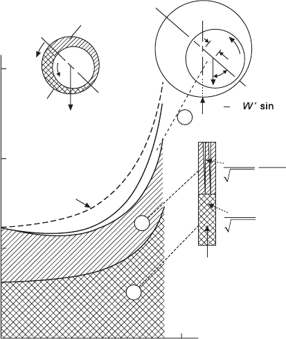
q = 2p
q = 0.2p
q = p
q = p
q = 0
Ruptured
fi l m
Full width
fi l m
2p Film
shear
h
max
h
min
q
F
10.21 Schematic diagram showing power loss components for steady
load conditions (from Martin, 1985).
Diesel-Xin-10.indd 714 5/5/11 12:00:40 PM
715Friction and lubrication in diesel engine system design
© Woodhead Publishing Limited, 2011
be calculated by either a simplied approach using an equivalent boundary
friction coefcient multiplied by the acting load and bearing radius, or a
more sophisticated approach to include the hydrodynamic lubrication friction
equations introduced in the previous section.
Suhara et al. (1997) measured piston pin boss bearing friction of a semi-
oating press-t piston pin in an automobile gasoline engine. They found the
piston pin bearing friction force increased with the cylinder pressure in the
second half of the compression stroke, the expansion stroke, and the rst half
of the exhaust stroke. They observed there was a spike in the friction force
occurring at full load immediately after the ring TDC where the cylinder
pressure was the highest. Another much smaller spike occurred at 90° crank
angle after the ring TDC when the connecting rod changed direction. The
friction force spikes indicated the boundary lubrication characteristics of the
piston in those regions. Suhara et al. (1997) found the piston pin friction
was in the range of 6.5% (at half load) to 16% (at full load) of the friction
mean effective pressure (FMEP) of the piston skirt and rings, and was not
negligible. Their ndings are very similar to the analytical simulation ndings
when the boundary friction is assumed for the piston pin in the simulation
(Xin, 1999). The piston pin and the small-end of the connecting rod only
rock slightly back and forth. The piston pin friction force can be calculated
by multiplying the pin load with an equivalent friction coefcient.
A very interesting Stribeck diagram was published by Suhara et al.
(1997) for the piston pin bearing. They observed that the coefcient of
friction decreases as the duty parameter decreases during the second half
of the compression stroke, indicating a hydrodynamic lubrication operation.
The coefcient of friction sharply increases as the duty parameter further
decreases during the rst half of the expansion stroke, indicating the piston
pin bearing operates in the mixed lubrication regime. Suhara et al. (1997)
believed that the rising, high friction coefcient with the duty parameter in
the second half of the expansion stroke was caused by a very thin oil lm
which did not thicken with the increasing duty parameter. This suggested
insufcient supply of lubricant oil in that region. They pointed out that
design improvement to reduce friction should be emphasized for both the
boundary lubrication regime in the rst half of the expansion stroke and the
oil starvation regime in the second half of the expansion stroke.
A small reduction in surface roughness may greatly reduce the piston pin
friction, as indicated by Suhara et al. (1997) in their extensive experimental
investigation on various design effects on piston pin friction. Improving the pin
boss bearing material also has a large effect on friction reduction. Reducing
bearing clearance of the piston pin boss, for example for noise reduction,
may incur a friction increase in the boundary lubrication regime due to more
severe asperity contacts, especially at full load under high cylinder pressures.
Excessively reducing piston pin length and wall thickness, for the reason of
Diesel-Xin-10.indd 715 5/5/11 12:00:40 PM
716 Diesel engine system design
© Woodhead Publishing Limited, 2011
weight reduction, may cause a large increase in unit loading and pin boss
bearing deformation. This can lead to an increase in boundary friction and
wear, unless other design measures are taken for counterbalance (e.g., use
a better bearing material, reduce surface roughness, improve oil feed).
10.7 Valvetrain lubrication and friction
10.7.1 System design considerations for valvetrain friction
While the valvetrain can be classied as a part of the mechanical systems in the
engine just like the piston and the bearings, it is also one of the four essential
constituents to form the air system for a modern diesel engine. The other
three constituents are the manifolds, the turbocharger, and the EGR system.
The central functions of the valvetrain are to deliver the gas ow into the
engine with high volumetric efciency and to achieve certain special functions
such as engine brake or advanced combustion via air ow management.
The source of friction comes from its functional requirements and design
arrangement. Valvetrain friction has distinct characteristics compared with
its tribological counterparts such as the piston skirt, the piston rings, and the
bearings. While valvetrain friction is relatively small compared to the pistons
and the rings (except at low speeds), the cam–follower interface is the most
challenging tribological interface in the engine due to boundary lubrication.
Failure to manage valvetrain friction can cause widespread durability issues.
Understanding and analyzing valvetrain friction and lubrication are of vital
importance to an engine system engineer.
There are two types of valvetrains: the conventional valvetrain (i.e., the
pushrod or the overhead types) and the advanced VVA system. Discussion
of the friction losses of VVA is outside the scope of this book. In the
conventional valvetrain, the poppet valve has proven to be the best. Other
types of valving such as sleeve or rotary valves suffer from poor lubrication,
bad sealing, high friction, and high oil consumption. The pushrod valvetrain
has been the preferred choice for heavy-duty low-speed engines due to its
many virtues such as good characteristics of lubrication (e.g., abundant
oil availability, freely rotating tappet), wear, and packaging. The main
disadvantage of the pushrod valvetrain is its low stiffness and excessively
high vibration at high speeds. Therefore, high-speed engines tend to use the
much stiffer overhead-cam (OHC) valvetrain despite the challenges in design
and lubrication, especially for the pivoted follower. They operate in more
arduous and hotter environments and are located in the cylinder head with
less lubricant naturally available. There are two types of OHC valvetrains,
namely direct acting and pivoted follower. Different congurations have
their own unique characteristics of stiffness, valevtrain dynamics, spring
force, lubrication and wear. For example, the direct acting OHC has to use
Diesel-Xin-10.indd 716 5/5/11 12:00:40 PM
717Friction and lubrication in diesel engine system design
© Woodhead Publishing Limited, 2011
a very large cam lobe to achieve very fast valve lift, requiring the use of
large camshaft bearings and resulting in higher bearing friction. The choice
of valvetrain conguration is very complex and is a system-level design
topic related to performance, durability, packaging, and cost. Friction is a
key attribute in valvetrain performance.
Valvetrain friction occurs mainly at the cam–follower interface. Rocker
arm, camshaft bearings, seals, valve guide and follower–bore also contribute
to the friction. There are two types of followers, at-faced and roller. The
roller follower has much lower friction than the at-faced follower, and
modern pushrod valvetrains usually use roller followers to reduce friction
and sustain the high cam stress required (Chapter 2). The at-faced follower
has been universally used in the direct acting OHC, while the roller follower
has been widely used in many pivoted follower OHC valvetrains. The rocker
arm can either have a shaft (journal bearing) contact or rolling contact at
the pivot. This choice affects the rocker friction signicantly.
At low engine speeds, the source of valvetrain friction is the spring
force, which reaches its highest level at the cranking speed and at the cam
nose when the engine valve is fully open. The spring force is determined to
control valve oating and valvetrain separation. At high engine speeds, the
valvetrain inertia effect starts to grow to offset the spring force. The inertia
force can become so high that the cam force may reach the highest level
at the cam ank rather than at the cam nose. At high load conditions, the
cylinder pressure is very high and the gas loading acting at the exhaust valve
opening (EVO) is also high. This gas loading may produce the highest cam
force at the EVO within an engine cycle. Similarly, at the high speed no-fuel
motoring condition, the recompression pressure can be very high due to the
high exhaust manifold pressure, and it can cause a very high cam force at
the intake valve opening.
The cam–follower contact has proven to operate in the most arduous
tribological conditions within the internal combustion engine. Due to the
high cam force and the relatively slow rotating velocity at the interface,
the cam–follower is a concentrated contact and had been believed for a
long time to operate in the boundary lubrication regime. As pointed out by
Taylor (1991), this traditional view may well have delayed the widespread
application of the thin-lm lubrication theory to this interface. Taylor (1993b)
cited Müller’s research work (Müller, 1966) on two cam designs dating back
to the 1960s, where one cam had lower Hertzian stress and lower oil lm
thickness at the cam nose, and the other cam had higher Hertzian stress and
higher oil lm thickness. The test result showed that the rst cam suffered
scufng followed by pitting while the second cam performed satisfactorily.
This example shows that some elements of elastohydrodynamic lubrication
occur at the cam–follower interface so that the design changes affecting the
oil lm thickness may play an important role. Moreover, it has been found
Diesel-Xin-10.indd 717 5/5/11 12:00:40 PM
718 Diesel engine system design
© Woodhead Publishing Limited, 2011
that the majority of the cam ank region is covered by a relatively thick
oil lm except for the narrow cam nose region under elastohydrodynamic
lubrication (Taylor, 1994). Only around the cam nose does the oil lm
thickness become very thin, and the additive package of a lubricant may
provide effective protection via the boundary reaction lm. Therefore, the
overall lubrication mode should be better described as mixed lubrication,
as suggested by Taylor (1991). Unfortunately, the outcome of that research
from the 1960s was lost and research on valvetrain lubrication has lagged
behind the bearings and the piston assemblies in general. Since the 1980s,
research into applying the elastohydrodynamic lubrication principles to
valvetrain problems has started to become more active.
Oil lm thickness at the cam–follower interface can be changed by design.
The oil lm thickness at several critical locations is related to durability and
wear, for example, at the cam nose and the opening ramp. Cam–follower friction
can be better predicted with the mixed lubrication theory. On the durability
side, cam stress is not the only dominant parameter to judge the durability of
wear. Lubrication plays an equally vital role, and different oil lm thickness
may alter the corresponding allowable stress limit. The modern view of the
valvetrain design criteria emphasizes the equal importance of using both the
traditional design criteria derived from the view of the boundary lubrication
(i.e., the maximum Hertzian contact stress, ash temperatures, lubricant
additives, and material specications) and the mixed/elastohydrodynamic
lubrication principles to improve the minimum oil lm thickness for a
reliable cam–follower interface design with minimum friction and wear. In
fact, the modern mixed/elastohydrodynamic lubrication theory may help
improve the design criteria used in the traditional view. For example, the
more accurate calculation of the friction force by using the modern mixed
lubrication theory directly improves the accuracy of the prediction of ash
temperature and cam surface temperature (to be detailed later).
The following are the three central tasks for the engine system engineer
in valvetrain friction/lubrication work:
∑ minimizing valvetrain loading through air system optimization
∑ optimizing the cam prole/size to promote lubrication
∑ optimizing the tribological interfaces (e.g., selecting the roller and
material, optimizing surface topography, predicting oil lm thickness
and friction losses).
The cam–follower interface is also subject to wear due to surface asperity
contacts and high ash temperature. Wear modeling is related to valvetrain
loading optimization, hence is an important part of system durability and
reliability. These topics are discussed in Chapter 2 (see also Colgan and Bell,
1989). This section focuses on cam lubrication and friction.
Diesel-Xin-10.indd 718 5/5/11 12:00:40 PM
719Friction and lubrication in diesel engine system design
© Woodhead Publishing Limited, 2011
10.7.2 Characteristics of valvetrain friction
Valvetrain friction is usually the second highest mechanical friction in the
engine after the piston assembly. Among the friction losses of the various
engine components, the valvetrain may account for 40% of the total friction
at low speeds and 10% at high speeds. As a comparison, the piston assembly
and the bearings may account for approximately 35% of the total friction at
low speeds and 50% at high speeds. The crankshaft bearings may account for
5% at low speeds and 15% at high speeds. The water pump, the oil pump, and
the alternator may account for 20% at low speeds and 25% at high speeds.
Reducing valvetrain friction is important because a friction reduction at low
speeds has a large impact on fuel economy for many vehicles running in
part-load driving cycles (e.g., especially in urban city driving).
Valvetrain lubrication and friction are characterized by the following three
aspects:
1. Different types of friction interfaces operating in different lubrication
regimes exist for various valvetrain components. They respond differently
to the changes in design and operating parameters.
2. Different friction interfaces have different characteristics of instantaneous
dynamic loading and relative velocities within an engine cycle.
3. The relative proportions of each friction interface determine the overall
behavior of the entire valvetrain friction.
The following friction interfaces exist in the valvetrain:
∑ cam–follower (mainly in the severe mixed or boundary lubrication
regime, or precisely speaking, boundary lubrication dominates near the
cam nose, while elastohydrodynamic lubrication dominates on the cam
anks)
∑ roller pin–bearing of a roller follower
∑ rocker–fulcrum (either a shaft or ball joint; usually in boundary
lubrication)
∑ camshaft journal–bearing (mainly in hydrodynamic lubrication)
∑ camshaft seals (in boundary lubrication)
∑ follower–bore (in hydrodynamic lubrication)
∑ valve–guide (in hydrodynamic lubrication)
∑ valve stem seals (in boundary lubrication)
∑ other miscellaneous, low friction interfaces (e.g., rocker–bridge or
rocker–valve stem tip, pushrod sockets).
In hydrodynamic lubrication, the friction is mainly viscous shear and it is
proportional to sliding velocity and lubricant viscosity. In elastohydrodynamic
lubrication, the surface asperities deform and the lubricant viscosity changes
drastically with the lubricating oil lm pressure. Because the contact geometry
Diesel-Xin-10.indd 719 5/5/11 12:00:40 PM