Xin Q. Diesel Engine System Design
Подождите немного. Документ загружается.

680 Diesel engine system design
© Woodhead Publishing Limited, 2011
10.4 Piston-assembly lubrication dynamics
10.4.1 Friction characteristics and piston assembly design
From the perspective of multi-body dynamics modeling, the piston assembly
includes the piston skirt, the rings, the piston pin (SAE J2612, 2002), and
the connecting rod. The discussion in this section focuses on the lubrication
dynamics of the piston body and the skirt. The piston rings will be discussed
in Section 10.5. The piston pin bearing, the connecting rod big-end bearing,
and the crankshaft main bearing are discussed in Section 10.6.
The piston in modern diesel engines needs to have strong thermo-mechanical
strength to withstand the peak cylinder pressure and the temperature. It also
needs to have low friction and wear, low piston slap noise, good control on
skirt distortion, proper cooling and lubrication, and light weight (for high-
speed operation), and match with the combustion chamber shape. Piston rings
seal the in-cylinder gas with little blow-by, transfer heat from the piston to
the cylinder liner, and control the lube oil consumption. Low-friction piston
assembly design is very important for fuel consumption. Both analytical and
experimental methods play critical roles in piston tribological design.
Piston slap has been identied as the main cause of the cylinder liner
cavitation in heavy-duty diesel engines due to the high impact energy of the
slap. Piston slap noise can also be the most prominent mechanical noise during
warm-up. Mechanical noises emitted from the engine surface are caused by
the impact between the components and the resulting vibration. They become
louder as the engine speed increases. In piston tribological design, the piston
skirt friction power, the dynamic minimum lubricating oil lm thickness, and
the cold piston slap kinetic energy (or noise) are the three most important
performance parameters that should be optimized simultaneously.
While undergoing a primary reciprocating motion inside the cylinder, the
piston is pushed laterally by the alternating side thrust force from the thrust
side to the anti-thrust side, and vice versa, several times within the skirt-
to-bore clearance during an engine cycle. The side thrust force is generated
by the reaction force from the connecting rod small end, which is a force
generally not in the piston’s sliding direction, to resist the combined gas and
inertia forces. The lateral (transverse) motion is accompanied by a small
tilting motion around the piston pin due to the moments acting on the piston
from various forces. These secondary motions cause the piston to slap on
the cylinder bore at skirt top and bottom, accompanied by a sliding motion
changing from mixed lubrication at the TDC or the BDC to hydrodynamic
lubrication at the mid-stroke. Piston-assembly dynamics is an area related to
piston skirt secondary motions (lateral and tilting) and their associated piston
slap, friction, and wear. Its research started in the 1960s, evolving from the
single-body dynamics without lubrication to the more complex multi-body
dynamics coupled with elastohydrodynamic lubrication models.
Diesel-Xin-10.indd 680 5/5/11 12:00:28 PM
681Friction and lubrication in diesel engine system design
© Woodhead Publishing Limited, 2011
The piston secondary motions not only affect the piston slap noise (to be
detailed in Chapter 11), but also affect the piston ring operation and wear.
In order to achieve low blow-by and oil consumption, the piston lateral
movement and titling need to be minimized to provide a good platform for
the piston rings to operate (Wacker et al., 1978). Large piston tilting may
cause the rails of the oil control ring to move away from the cylinder wall
so that the ring loses its oil control ability. The piston secondary motions
also affect the diesel cylinder bore polishing which is caused by the top land
carbon deposit (Guertler, 1986). Moreover, the piston secondary motions
affect piston skirt friction, and this topic is detailed below.
Piston skirt lubrication and friction are affected by the skirt-to-bore clearance
and the oil lm thickness distribution on the skirt which is related directly to
the side thrust and the piston secondary motions. The piston-assembly friction
of diesel engines can account for 40–55% of the total engine mechanical
friction (Richardson, 2000), with the piston skirt contributing about 15–20%,
the piston rings 15–20%, and the connecting rod 10–14%.
Piston skirt friction characteristics have been researched extensively. Feuga
and Bury (1984) measured the friction force and power loss of a gasoline
piston–ring–liner assembly at various engine speeds and loads, and with
different lubricant oil grades. They found that the piston-assembly FMEP
(including the rings) increased with engine speed and load. At higher loads the
frictional loss in the expansion stroke was higher than that in other strokes,
and this characteristic was especially prominent at low speeds. Wakabayashi
et al. (2003) found from measurement that the effect of gasoline engine load
on the piston skirt friction during the expansion stroke was small. Nakayama
et al. (1997) measured the piston skirt friction force of a gasoline engine and
found that the piston skirt could operate in the mixed lubrication regime in
the expansion stroke, and the friction force in the rst half of the expansion
stroke could be reduced by changing the piston pin offset from the thrust
side to the anti-thrust side.
Many design parameters affect piston-assembly dynamics. For example, the
secondary movement can be reduced or diminished by using smaller clearance,
piston pin offset or optimized skirt prole. An early comprehensive summary of
the design guidelines was given by Winship (1967). He pointed out that a thin
thickness of the major thrust side of the upper skirt was especially important
for noise control, and a shorter skirt length (measured from the piston pin
centerline) affected piston tilting, blow-by, and oil consumption. Oetting et al.
(1984) illustrated that a reduced reciprocating mass and a long connecting rod
(i.e., reduced crank–conrod ratio) reduced the piston side thrust and achieved
low piston slap noise. Uras and Patterson (1987) measured piston friction and
found that friction did not increase with increased piston weight.
Mansouri and Wong (2004) used numerical simulation for a natural gas
engine to nd that the piston skirt friction power was inversely proportional
Diesel-Xin-10.indd 681 5/5/11 12:00:28 PM
682 Diesel engine system design
© Woodhead Publishing Limited, 2011
to the oil lm thickness and approximately directly proportional to the surface
waviness. The ‘waviness’ refers to the circumferential machining tracks of
saw-tooth shape for oil retention on the surface to prevent scufng. It is two
orders of magnitude higher than the surface ‘roughness’. They also found
that a atter skirt prole and a less rigid skirt could reduce the proportion of
the boundary lubrication relative to the hydrodynamic lubrication friction. It
should be noted that signicant boundary lubrication scraping may occur during
the expansion stroke, especially for the skirts having large waviness.
Crankshaft offset is another important parameter extensively investigated by
many researchers (Haddad and Tjan, 1995; Nakayama et al., 2000; Wakabayashi
et al., 2003; Shin et al., 2004). Crankshaft offset may reduce the piston side
thrust and skirt tilting; and it may reduce piston friction during the expansion
stroke if the friction occurs in the boundary or mixed lubrication regime. In
fact, as long as the piston skirt is designed to stay within the hydrodynamic
lubrication regime, any side thrust change basically would not affect the skirt
friction appreciably. Crankshaft offset has a strong interaction with piston pin
offset and piston pin vertical position. Crankshaft offset may either promote
or destroy the hydrodynamic lubrication on the skirt, resulting in different
conclusions on piston skirt friction accordingly.
Piston skirt prole design was addressed using an experimental method
by Yagi and Yamagata (1982). They used a composite material (epoxy resin)
to cover the piston skirt surface and run the engine to naturally wear off the
material at highly stressed areas. Finally the smoothly curved, barrel-shape
piston skirt prole dened by the composite material remaining after the
marking test was adopted as the nal optimized cold prole. With this method,
different proles to minimize wear and scufng at the thrust and anti-thrust
sides can come out of a real engine test. It should be noted that the prole
produced by such a marking method minimizes the wear and scufng only for
a given piston design (e.g., with a given pin offset). Different piston designs
may produce different resulting proles. This method cannot identify which
design gives the desirable minimum piston tilting. Piston dynamics simulation
is able to complement that aspect and is an important tool in piston design.
Teraguchi et al. (2001) conducted experimental work on a small diesel
engine and found that a forced oil supply remarkably reduced the skirt friction
force by 20% in the expansion stroke on the thrust side and the latter half of
the exhaust stroke, without a signicant penalty on oil consumption. They
found that the effectiveness was equivalent to the friction reduction achieved
by using a MoS
2
coated skirt.
10.4.2 History of piston-assembly lubrication dynamics
Although piston slap can be modeled effectively with multi-body dynamics
to calculate the side thrust and the titling moment without using a skirt
Diesel-Xin-10.indd 682 5/5/11 12:00:28 PM
683Friction and lubrication in diesel engine system design
© Woodhead Publishing Limited, 2011
lubrication model, such a model cannot be used to predict skirt friction
accurately because in reality the skirt operates mainly in the hydrodynamic
lubrication regime and hence the oil lm thickness simulation becomes critical.
Dry contact modeling with Coulomb friction yields unrealistically high skirt
friction force compared to the normal engine operation with lubrication.
Piston-assembly dynamics modeling without lubrication will be discussed
in more detail in Chapter 11 for the topic of piston slap noise.
Unlike the piston ring lubrication which can be reasonably simplied as
a one-dimensional problem of lubricating oil lm pressure distribution only
along the axial direction because the ring can be regarded circumferentially
uniform, the piston skirt lubrication must be modeled as a two-dimensional
problem for oil lm pressure distribution. The lubrication modeling for
the piston skirt with the rigid-body assumption and the numerical solution
of the two-dimensional Reynolds equation was conducted by Knoll and
Peeken (1982), Li and Ezzat (1983), Zhu et al. (1992), Chittenden and
Priest (1993), Nakada et al. (1997), and Livanos and Kyrtatos (2006). Oil
starvation and cavitation modeling is important for predicting the piston
secondary motions. Keribar and Dursunkaya (1992a) showed in simulation
that the piston secondary motions under fully ooded and partially ooded
skirt lubrication were signicantly different.
Piston thermal deformation was simulated with a nite element model by
Li (1982). Piston skirt elastic deformation was simulated by Kimura et al.
(1999). The piston skirt experiences signicant deformations caused by thermal
expansion, mechanical loading, and lubricating oil lm pressure, especially
for the thinner, more exible light-duty or articulated piston skirts. Typical
skirt deformations are of the same order of magnitude as, or larger than,
the skirt-to-bore clearances. Elastohydrodynamic lubrication for the piston
skirt has been modeled by Oh et al. (1987), Blair et al. (1990), Goenka and
Meernik (1992), Keribar and Dursunkaya (1992a, 1992b), Dursunkaya and
Keribar (1992), Keribar et al. (1993), Zhu et al. (1993), Dursunkaya et al.
(1993, 1994), Wong et al. (1994), Knoll et al. (1996), Scholz and Bargende
(2000), Offner et al. (2001), and Shah et al. (2007).
Goenka and Meernik (1992) compared three lubrication models with
experimental data. The three models are: (1) a simple model considering only
the ‘squeeze effect’ and the lateral motion by ignoring the ‘wedge effect’
and the tilting motion; (2) a rigid-body hydrodynamic lubrication model
by ignoring the thermal expansion and the compliance; and (3) a mixed-
elastohydrodynamic lubrication (DEHD) model. They concluded that both the
rigid-body and DEHD models could predict piston skirt friction reasonably
well, while the simple model was only acceptable for trend predictions.
The DEHD model was recommended for more accurate analysis used in
component design. Dursunkaya et al. (1993) pointed out that, compared to
the elastohydrodynamic lubrication simulation, the rigid skirt hydrodynamic
Diesel-Xin-10.indd 683 5/5/11 12:00:28 PM
684 Diesel engine system design
© Woodhead Publishing Limited, 2011
lubrication model could yield large discrepancies in the boundary friction.
Knoll et al. (1996) used a nite element method to present small differences
in piston secondary motions between the rigid and the elastic skirt simulation
results for a diesel engine. Carden et al. (2006) concluded that a relatively
simple model could be used to provide credible predictions of piston assembly
friction loss even if the model did not have the advanced features such as
elastohydrodynamic lubrication, nite element, and bore distortion.
Sophisticated piston skirt lubrication dynamics modeling can be conducted
with commercial software packages, such as Ricardo’s PISDYN (Keribar
et al., 1993; Carden et al., 2006) and AVL’s GLIDE. The simulation of
deformable-piston dynamics coupled with elastohydrodynamic lubrication
can also be conducted with commercial nite-element software packages, as
performed by several authors mentioned above (Knoll et al., 1996; Scholz
and Bargende, 2000; Offner et al., 2001).
10.4.3 Formulation of piston-assembly lubrication
dynamics
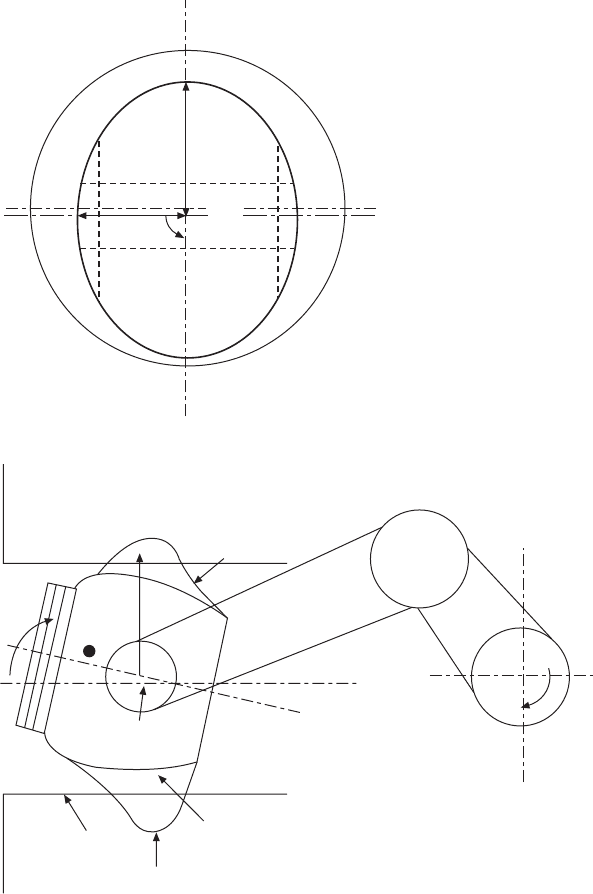
An analytical model of piston lubrication dynamics is shown in Fig. 10.6.
The following design and operating parameters affect the piston dynamics:
(1) piston mass (including the piston pin); (2) connecting rod mass; (3) piston
tilting moment of inertia; (4) connecting rod rotating moment of inertia; (5)
piston skirt-to-bore clearance; (6) piston center of gravity positions (lateral
and vertical); (7) piston pin positions (lateral and vertical); (8) piston skirt
length; (9) piston skirt lubrication wetted arc angle; (10) piston skirt axial
prole and ovality; (11) lubricant oil viscosity; and (12) engine speed and
load. The outputs of the model include the piston primary motion (i.e., the
reciprocating sliding motion) and the piston skirt secondary motions (i.e., the
lateral and tilting motions within the skirt-to-bore clearance), the lubricating
oil lm thickness and the pressure distribution on the piston skirt, the friction
forces in the hydrodynamic lubrication regime and the metal-to-metal contact
scraping regime.
The analytical model includes piston assembly multi-phase multi-body
dynamics coupled with piston skirt lubrication. The side thrust (the lateral
force acting on the piston pin) results from the cylinder gas pressure and the
inertia forces, and induces the piston lateral motion. Piston tilting is caused
by the moments acting on the piston skirt from various forces (i.e., the side
thrust, the vertical force acting on the piston pin, the cylinder pressure,
the lubricating oil lm forces (also called lubricant forces), the friction
forces between the skirt and the rings, and the piston pin friction force).
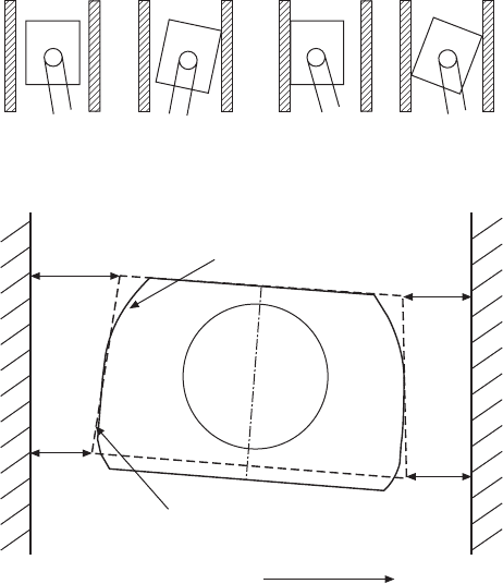
The multi-phase used in the dynamic modeling includes a normal phase
without scraping, a single-corner or single-location scraping phase, and a
two-corner or multi-location scraping phase (Fig. 10.7). The scraping refers
Diesel-Xin-10.indd 684 5/5/11 12:00:28 PM
© Woodhead Publishing Limited, 2011
10.6 Illustration of piston-assembly lubrication dynamics model.
Thrust side
Piston
Oil film
pressure
Crank pin
Cylinder bore
Oval piston in cylindrical
bore (top view)
Crankshaft
Connecting rod
Bore centerline
Piston
centerline
C.G.
Cylinder bore
P
lub,max
oil film
pressure
Barrel skirt
profile
Piston
pin
Lateral eccentricity
from bore centerline
(positive direction)
Piston
pin
Piston
skirt
b
a
The degree of ovality = 2(a-b)
h
o
j
0
0
Anti-thrust side
Tilting angle (positive direction)
Diesel-Xin-10.indd 685 5/5/11 12:00:28 PM
686 Diesel engine system design
© Woodhead Publishing Limited, 2011
to the boundary lubrication. In each phase, the dynamics equations can be
formulated for each component of the piston assembly (i.e., the piston skirt
and the connecting rod) and the crankshaft based on the force balance using
Newton’s second law F = ma for the lateral and vertical motions and the
moment balance for the rotation. More details about the dynamic equations
in piston-assembly dynamics modeling are provided in Shiao and Moskwa
(1993) and Xin (1999).
The multi-body dynamics modeling approach is much more accurate than
the commonly used ‘point mass’ simplication of the connecting rod for
piston side thrust calculations. The ‘point mass’ method treats the connecting
rod as two point masses concentrated at the small end and the big end,
respectively, rather than as a rigid body. An example of the importance of
accurate formulation of the piston skirt side thrust calculation is given in Fig.
10.8. It shows that the error due to the simplied ‘point mass’ approximation
can be as great as 20%.
The transition between different phases of the motion is handled by rigid-
body impact dynamics based on the impulse and momentum balances. For
Normal phase Scraping phase 1 Scraping phase 2
Illustration of three phases of piston motion in the thrust plane
Corner 4
Corner 1
h4
h3
Real cold skirt profile
h1
h2
Piston skirt
Piston pin
Corner 3
Cylinder bore
Corner velocity positive direction
Corner 2
Simplified conic skirt shape for cold piston
slap simulation without effective lubrication
10.7 Multi-phase dynamics model of the piston and definition of
piston skirt corners.
Diesel-Xin-10.indd 686 5/5/11 12:00:28 PM

687Friction and lubrication in diesel engine system design
© Woodhead Publishing Limited, 2011
example, when the oil lm thickness becomes lower than a certain threshold
value, piston-to-liner impact is assumed to occur with a non-zero piston
lateral impact velocity. Rebound occurs after each impact, and a coef cient
of restitution is assumed for calculating the piston lateral velocity after the
rebound. When the piston impact velocity becomes suf ciently small after
a series of impact and rebound events and if there is still a non-zero normal
force pushing the piston against the bore, a scraping motion is assumed to
occur with boundary lubrication. When the normal force vanishes as the
piston side thrust changes, the piston may leave the scraping phase and
switch to a normal phase. Such a sophisticated high- delity model may not
only predict the friction during the scraping phases, but also simulate the
transient piston slap behavior before the scraping occurs.
The lubrication model is based on the viscous uid Reynolds equation.
The equation can be solved with the nite-difference numerical method for
the lubricating oil lm pressure distribution after the piston skirt secondary
motions are computed at each time step. The three-dimensional oil pressure
distribution is then integrated over the skirt surface to obtain the lubricant
force and moment, which are used in the piston dynamics model at each
time step. The Reynolds equation governing the lubricating oil lm pressure
on the piston skirt is given as (Xin, 1999):
∂
∂
∂
∂
Ê
Ë
Ê
Ë
Ê
Ê
Á
Ê
Ë
Á
Ë
Ê
Ë
Ê
Á
Ê
Ë
Ê
ˆ
¯
ˆ
¯
ˆ
ˆ
˜
ˆ
¯
˜
¯
ˆ
¯
ˆ
˜
ˆ
¯
ˆ
∂
∂
∂
∂
Ê
Ë
Ê
Ë
Ê
Ê
Á
Ê
Ë
Á
Ë
Ê
Ë
Ê
Á
Ê
Ë
Ê
Ë
Á
Ë
ˆ
¯
ˆ
¯
ˆ
ˆ
˜
ˆ
¯
˜
¯
ˆ
¯
ˆ
˜
ˆ
¯
ˆ
y
∂y∂
h
p
∂p∂
y
∂y∂
r
h
p
∂p∂
o
lu
b
P
r
P
r
o
lu
b
3
2
3
1
+
∂
∂
¯
¯
¯
˜
¯
¯
˜
¯
Ë
Ë
∂
∂
Ë
Á
Ë
Ë
Á
Ë
h h
o
o
2
2
=
jj
∂
jj
∂
Ë
jj
Ë
Ë
Á
Ë
jj
Ë
Á
Ë
o
jj
o
–
61
+61 +
2
mm
61
mm
61
61
mm
61
+61 +
mm
+61 +
2
mm
2
mm
vP
mm
61
mm
61
vP
61
mm
61
o
61
o
61
61
mm
61
o
61
mm
61
v
o
61
mm
61v61
mm
61
mm
vP
mm
v
mm
vP
mm
61
mm
61
vP
61
mm
61v61
mm
61
vP
61
mm
61
h
61
h
61
y
mm
y
mm
h
t
∂
61
∂
61
∂
mm
∂
mm
61
mm
61
∂
61
mm
61
y∂y
mm
y
mm
∂
mm
y
mm
∂
∂
10.24
where y represents the axial direction of the piston skirt, j represents the
circumferential direction of the skirt, r
P
is the piston radius, h
o
is the oil
lm thickness, p
lub
is the lubricating oil lm pressure, m
v
is the dynamic
oil viscosity, v
P
is the piston sliding velocity, and t is time. Equation 10.24
shows that the oil lm pressure, the gradient of the oil lm pressure and
hence the viscous shear friction force all increase linearly with piston sliding
velocity and oil viscosity.
0 180 360 540 720
Multi-body dynamics
‘Point mass’ approximation
Crank angle (degree)
Side load on piston (N)
4000
2000
0
–2000
–4000
–6000
–8000
10.8 Piston side thrust calculated with different methods (1800 rpm,
70% load).
Diesel-Xin-10.indd 687 5/5/11 12:00:29 PM
688 Diesel engine system design
© Woodhead Publishing Limited, 2011
The viscous shear friction force is calculated by integrating the viscous
shear stress over the lubricated area on the piston skirt. The viscous friction
force increases with the skirt length and the piston diameter, and decreases
when the skirt-to-bore clearance increases. The hydrodynamic friction
force can be calculated as the summation of the viscous shear term and the
hydrodynamic pressure term, ignoring the translation or squeeze term. The
total piston skirt friction force is equal to the sum of the hydrodynamic
friction force and the boundary lubrication friction force if any, given as:
FF
F
v
h
h
fs
FF
fs
FF
kirt
FF
kirt
FF
fs
FF
fs
FF
kirt
hf
F
hf
F
skir
tb
v
P
o
o
,,
fs,,fs
kirt,,kirt
fs,,fs
hf,,hf
FF =FF
FF FF
fs
fs
FF
fs
FF FF
fs
FF
kirt
kirt
hf
hf
+
hf
+
hf
=
+
,,,,,,
fs,,fs,,fs,,fs
kirt,,kirt,,kirt,,kirt
,
tb,tb
m
222
∂
∂
Ê
Ë
Ê
Ë
Ê
Ê
Á
Ê
Ë
Á
Ë
Ê
Ë
Ê
Á
Ê
Ë
Ê
ˆ
¯
ˆ
¯
ˆ
ˆ
˜
ˆ
¯
˜
¯
ˆ
¯
ˆ
˜
ˆ
¯
ˆ
ÚÚ
Ú
p
∂p∂
y
∂y∂
Af
Ú
Af
Ú
pA
lu
b
cf
Ú
cf
Ú
Af
cf
Af
Ú
Af
Ú
cf
Ú
Af
Ú
ri
cfricf
ba
pA
ba
pA
sp
pA
sp
pA
erity
pA
erity
pA
A
Ú
A
Ú
c
c
d+
Afd+Af
Af
cf
Afd+Af
cf
Af
d
pAdpA
,
ri,ri
10.25
where p
asperity
is the asperity contact pressure used in the load-carrying asperity
models of the mixed lubrication. For more comprehensive coverage about
the squeeze term in the friction power of bearings, the reader is referred to
Martin (1985) and Taylor (1993a). Note that on the cavitation side of the skirt,
although the friction is usually reduced by a certain extent due to the air/
vapor pockets in the ruptured lubricant lm streams, the viscous shear friction
force is still signi cant and cannot be completely neglected. The piston skirt
friction power is equal to the friction force multiplied by the piston sliding
velocity. The calculation of the friction torques at the piston pin bearing and
the conrod big-end bearing can often be simpli ed by multiplying the resultant
force with an assumed friction coef cient and the bearing radius.
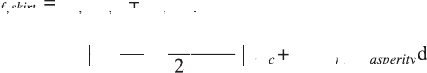
Lubrication boundary conditions are important for the prediction of the
lubricating oil lm thickness and the pressure distribution on the piston
skirt. The boundary conditions include fully ooded or partially ooded on
the skirt surface, and also include a lubricant cavitation condition once a
negative lubricating oil lm pressure is calculated. The cavitation conditions
usually include the non-mass-conserving half-Sommerfeld boundary condition
and the mass-conservation Reynolds or Jakobsson–Floberg–Olsson (JFO)
boundary condition. The comparison between different cavitation boundary
conditions for the piston skirt lubrication is provided in Fig. 10.9. It shows
that the half-Sommerfeld condition generally gives more conservative results
in the minimum oil lm thickness, i.e., smaller oil lm thickness than that
given by the Reynolds condition. However, it seems the Reynolds cavitation
boundary condition is still the most appropriate cavitation condition for
piston skirt lubrication. More sophisticated lubrication modeling such as the
elastohydrodynamic lubrication, including the effects of bore distortion and
skirt deformation as well as the more complex models of lubricant viscosity,
may be used but the computing time will increase exponentially.
The piston skirt lubrication model can simulate both a cylindrical skirt
and a non-cylindrical skirt, e.g., a barrel shape in the axial direction with
Diesel-Xin-10.indd 688 5/5/11 12:00:29 PM
689Friction and lubrication in diesel engine system design
© Woodhead Publishing Limited, 2011
Lubricating oil film
pressure (Pa)
Lubricating oil film
pressure (Pa)
2,100,000
1,800,000
1,500,000
1,200,000
900,000
600,000
300,000
0
1,800,000
1,500,000
1,200,000
900,000
600,000
300,000
0
Thrust side
0°
0°
q
q
720°
720°
Pressure-time map on the thrust line (j = 90°)
with the Reynolds cavitation condition
Pressure-time map on the thrust line
(j = 90°) with the half-Sommerfeld condition
Thrust side
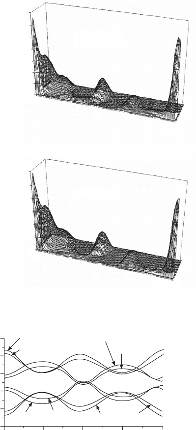
Skirt-to-bore clearance (mm)
0.1
0.08
0.06
0.04
0.02
0
0 180 360 540 720
Crank angle (degree)
h1 (S)
h1 (R)
h3 (S)
h3 (R)
h2 (S)
h2 (R)
h4 (S)
h4 (R)
Trajectories of piston secondary motions (the
half-Sommerfeld condition and the Reynolds
condition)
10.9 Comparison between half-Sommerfeld and Reynolds boundary
conditions of cavitation for piston skirt lubrication dynamics
(2000 rpm 70% load).
R = Reynolds condition
S = half-Sommerfield
condition
Crank angle (degree)
Crank angle (degree)
Skirt bottom
Skirt bottom
Skirt top
Skirt top
Diesel-Xin-10.indd 689 5/5/11 12:00:30 PM