Xin Q. Diesel Engine System Design
Подождите немного. Документ загружается.

660 Diesel engine system design
© Woodhead Publishing Limited, 2011
fundamental aspects: (1) lubrication regimes and friction types; (2) surface
topography; and (3) lubricant property. There are basically two approaches to
calculate the friction force on the lubricated engine components: (1) for the
constantly loaded viscous friction or Coulomb friction under a non-zero normal
load, a coefcient of friction multiplied by the normal load can be used; and
(2) for the dynamically unloaded viscous friction, the viscous shear friction
force needs to be calculated using equation 10.8, where the lubricating oil
lm thickness can be estimated using the component clearance or solved by
an empirical equation or the Reynolds equation. The level-1 friction model,
which ignores the instantaneous dynamically loaded or unloaded details,
uses the rst approach (a Coulomb-like method) as an approximation. The
level-2 and level-3 friction models should use the second approach of the
true viscous friction model because the instantaneous dynamic loading needs
to be calculated by using engine dynamics models.
As reviewed by Spikes (1997), there are ve stages of rough surface effect
as the lubricating oil lm thins:
∑ Stage 1: The surface roughness has no effect on the oil lm thickness.
Wear coefficient decreases
Stage 5:
asperity
contact only
Stage 4: load
shared by fluid
pressure and
asperity
Stage 3:
Thin film,
little asperity
contact
Stage 2:
Thick film,
no asperity
contact
Stage 1:
Thick film, no
impact due to
roughness
Engine bearings
Piston skirt
Piston rings
Boundary
Mixed
Load
Viscosity ¥speed
Film thickness/
roughness ratio (l),
or duty parameter
Elastohydrodynamic
Valvetrain (cam)
Hydrodynamic lubrication
Friction coefficient (in log scale)
1.0
0.1
0.01
0.001
10.3 The Stribeck diagram with lubrication regimes of engine
tribological components.
Diesel-Xin-10.indd 660 5/5/11 12:00:21 PM

661Friction and lubrication in diesel engine system design
© Woodhead Publishing Limited, 2011
∑ Stage 2: The surface roughness in uences the oil lm thickness, but
there is no surface asperity contact.
∑ Stage 3: Some asperity contact occurs, but the load is mainly carried by
the uid lubrication pressure.
∑ Stage 4: The load is shared by both the uid pressure and the asperity
contact.
∑ Stage 5: All the load is carried by the asperities.
The lubrication regimes are described by the well-known Stribeck diagram,
where the ‘coef cient of friction’ is de ned as the ratio of the total friction
force to the normal load (Fig. 10.3),
f
F
F
fr
f
fr
f
i
f
F
f
F
n
F
n
F
10.11
Note that equation 10.11 has the same form as Coulomb friction in appearance.
When F
n
= 0 and the viscous shear force F
f
≠ 0, f
fri
= ∞, where equation
10.11 becomes invalid for unloaded viscous friction. Mayo Hersey showed
approximately one century ago that the friction due to viscous shear was a
unique function of the product of viscosity and bearing rotational speed then
divided by the average load (i.e., the Hersey number or the duty number) for
a loaded lubricated contact (Dowson, 1998). Such a curve with the friction
coef cient plotted against the Hersey number is commonly known as the
‘Stribeck diagram’. The friction coef cient is a critical parameter related to
the lubrication regime. Usually, the lubrication regime is characterized by
a duty parameter
S
v
F
ub
v
n
F
n
F
=
m
10.12
where µ
v
is the dynamic viscosity of the lubricant oil, v is the relative
sliding velocity of the two surfaces, and
F
n
F
n
F
is the unit normal loading force
per length. There are three lubrication regimes, namely (1) hydrodynamic
lubrication (including elastohydrodynamic lubrication; e.g., the piston skirt
and the engine bearings); (2) mixed lubrication (e.g., the piston rings); and
(3) boundary lubrication (e.g., the cam–tappet interface). The behavior of the
coef cient of friction is different in each lubrication regime. The coef cient
of friction can be expressed as (Heywood, 1988):
f
fri
= C
b
f
fri,b
+ (1 – C
b
)f
fri,h
10.13
where f
fri,b
is the friction coef cient of the boundary lubrication involving
metal-to-metal contact. The coef cient f
fri,b
is affected by the surface nish and
the properties of the materials in contact. The coef cient f
fri,h
is the friction
Diesel-Xin-10.indd 661 5/5/11 12:00:22 PM

662 Diesel engine system design
© Woodhead Publishing Limited, 2011
coef cient of the hydrodynamic lubrication (modeled in detail in 10.15), and
C
b
is the metal-to-metal contact constant, varying between 0 and 1.
In the hydrodynamic lubrication regime, the friction force from the shearing
of the viscous lubricant between the surfaces is inversely proportional to the
lubricating oil lm thickness, given by (for a Newtonian uid)
F
Av
h
fv
F
fv
F
vc
Av
vc
Av
o
fv,fv
=
m
10.14
where A
c
is the lubricated contact area and h
o
is the oil lm thickness. A
thinner oil lm may develop a higher uid lm pressure and thus carry
higher loads. As the applied load increases, the oil lm thickness becomes
thinner and the coef cient of friction decreases, but the oil lm shear
gradient increases. The normal load increases by a greater percentage than
the percentage drop of the friction coef cient. Therefore, the friction force
increases as a net result. The oil lm thickness has a spatial distribution on
the component surface and exhibits a certain pattern with respect to crank
angle for the engine components. For instance, the minimum oil lm thickness
on a piston ring usually behaves like a half-sine wave as
h
o
(f) = C
1
+ C
2
|sin(f – C
3
)|
where f is crank angle, C
1
and C
2
are constants (C
1
is usually below 1
micron), and C
3
is a shift (C
3
≈ 10° crank angle). The actual thickness reaches
a minimum value a little after the TDC and the BDC and has the largest
value at the mid-stroke (shown by Arcoumanis et al., 1997).
Both the theoretical lubricating oil lm thickness (assuming smooth
surfaces) and the friction force increase proportionally with
m
vn
vF
vn
vF
vn
vF
vn
vF
vn
/
vn
/
vn
vF/vF
vn
vF
vn
/
vn
vF
vn
(Spikes,
1997) in the isothermal hydrodynamic lubrication. When
m
vn
vF
vn
vF
vn
/
vn
/
vn
vF/vF
vn
vF
vn
/
vn
vF
vn
increases,
the coef cient of friction basically increases in a linear fashion if using the
logarithmic scale on both axes (Fig. 10.3). The friction force is the viscous
drag of the oil lm for conformal contacts. The coef cient of friction in the
uid lm hydrodynamic lubrication regime typically ranges from 0.0005 to
0.005. In the elastohydrodynamic lubrication, the contact is more concentrated
than the hydrodynamic lubrication and the oil lm is thinner, resulting in
elastic distortion of the surfaces. As pointed out by Spikes (1997), for the
elastohydrodynamic lubrication in non-conformal contacts (e.g., in gears or
roller bearings), the oil lm thickness varies only marginally with the load
so that m
v
v is in fact a better duty parameter than
m
vn
vF
vn
vF
vn
/
vn
/
vn
vF/vF
vn
vF
vn
/
vn
vF
vn
. In this case, the
coef cient of friction slightly decreases with an increasing m
v
v, as shown in
Fig. 10.3.
When the duty parameter
m
vn
vF
vn
vF
vn
/
vn
/
vn
vF/vF
vn
vF
vn
/
vn
vF
vn
becomes smaller, the uid lm becomes
thinner and consequently the coef cient of friction decreases to a minimum
value. At this point, metal-to-metal surface asperity contact and wear start
Diesel-Xin-10.indd 662 5/5/11 12:00:22 PM

663Friction and lubrication in diesel engine system design
© Woodhead Publishing Limited, 2011
to occur. The low value of
m
vn
vF
vn
vF
vn
/
vn
/
vn
vF/vF
vn
vF
vn
/
vn
vF
vn
makes the hydrodynamic lubricating oil
lm pressure insuf cient to support the load by itself, and the load must
be carried by the asperity contact as well. From this point, the lubrication
enters the mixed lubrication regime. The coef cient of friction increases as
m
vn
vF
vn
vF
vn
/
vn
/
vn
vF/vF
vn
vF
vn
/
vn
vF
vn
reduces. In the mixed lubrication regime, the total friction consists
of the contributions from both the hydrodynamic element and the asperity
contact. The asperity contact can be modeled by the average shear stress
model developed by Patir and Cheng (1979).
Finally, a further reduction in
m
vn
vF
vn
vF
vn
/
vn
/
vn
vF/vF
vn
vF
vn
/
vn
vF
vn
makes the oil lm thickness much
smaller than the height of the surface asperities. This brings the lubrication
into the boundary lubrication regime where the metal-to-metal contact
dominates and there is no hydrodynamic lubrication pressure. In the boundary
lubrication, the physical and chemical actions of the thin oil lms attached to
the surfaces determine the tribological performance. The surface actions that
determine the behavior of the boundary lubricant include the following: the
physically adsorbed layers of the lubricant, the chemically adsorbed layers,
and the oil lms formed by chemical reactions. Friction modi er additives in
the lubricant have a major in uence by modifying the shear strength of the
boundary lubricant lm. When the load or the sliding speed at the contact
interface area is high, signi cantly high contact temperatures may occur. The
lubricating oil lm formed by the physical and chemical adsorption layers
cease to be effective above a certain temperature threshold. However, some
additives such as sulfur, zinc, and phosphorus in the lubricant may help to
maintain effective boundary lubrication. Special boundary lubricant can be
effective in the most arduous operating conditions in the engine. Therefore,
the friction is affected by the solid materials and the lubricant additives in the
boundary lubrication. The coef cient of friction is essentially independent of
oil viscosity, load, speed, and apparent area of the contact. The properties of
the bulk lubricant such as viscosity are of minor importance. The coef cient
of friction in the boundary lubrication is equal to the shear strength of the
material (or more realistically, the shear strength of the oil lm on the
surface) divided by the yield pressure of the material (Rosenberg, 1982).
The coef cient of friction in the boundary lubrication is basically a constant,
typically at 0.08–0.12. The mixed and boundary lubrication regimes are
responsible for the wear on the engine components.
The Stribeck diagram re ects the fundamental tribological characteristics
of a friction pair with a given geometry. For example, in the hydrodynamic
lubrication regime, different geometries (e.g., pro le, contact area, bearing
aspect ratio, clearance) will have different curves in the diagram. It can
be used to look up the coef cient of friction based on the duty parameter.
The Stribeck diagram is the foundation of the level-1 and level-2 engine
friction models used in engine system design. It can be obtained either
experimentally or numerically. When solved numerically, the friction shear
Diesel-Xin-10.indd 663 5/5/11 12:00:22 PM
664 Diesel engine system design
© Woodhead Publishing Limited, 2011
force of the hydrodynamic or elastohydrodynamic lubrication is calculated
by solving the Reynolds equation for the lubricating oil lm thickness and
the pressure distributions (e.g., by a level-3 friction model). The numerical
result is dependent on certain theoretical assumptions or simpli cations, such
as the ‘lubrication approximation’ introduced by Reynolds, surface roughness,
elastic deformation of the surfaces, lubricant properties (e.g., Newtonian or
non-Newtonian), oil starvation, or partially ooded lubrication. Generating
the Stribeck curves numerically for different component geometries with a
level-3 model can facilitate the friction calculations with the level-2 model.
Stanley et al. (1999) used the Reynolds equation to solve for different Stribeck
curves for different piston ring geometries.
The coef cient of friction in the hydrodynamic lubrication can be
expressed in the following form based on empirical experimental evidence
(Fig. 10.3):
fC
SC
v
pL
fr
fC
fr
fC
fC
ih
fC
lu
b
C
SC
C
SC
v
pL
l
pL
C
,
fC
,
fC
fC
ih
fC
,
fC
ih
fC
fC =fC
fC fC
SC= SC
00
SC
00
SC
lu
00
lu
SC
lu
SC
00
SC
lu
SC
b
00
b
SC
b
SC
00
SC
b
SC
00
SC SC
00
SC SC
SC
lu
SC SC
lu
SC
00
SC
lu
SC SC
lu
SC
SC
b
SC SC
b
SC
00
SC
b
SC SC
b
SC
SC= SC
00
SC= SC
1
SC
1
SC
1
m
Ê
Ë
Ê
Ë
Ê
Ê
Á
Ê
Ë
Á
Ë
Ê
Ë
Ê
Á
Ê
Ë
Ê
ˆ
¯
ˆ
¯
ˆ
ˆ
˜
ˆ
¯
˜
¯
ˆ
¯
ˆ
˜
ˆ
¯
ˆ
10.15
where C
0
and C
1
are the constants varying widely with component geometry
(e.g., C
1
= 0.3 ~ 1, often C
1
≈ 0.5 for the piston skirt and the piston rings
for approximate analysis), p
l
is the loading pressure acting on the sliding
component, L is the width of the component in the direction of motion (e.g.,
the thickness of the piston ring or the length of the piston skirt), and p
l
L
is the load per unit transverse length. McGeehan (1978) provided detailed
discussions on the coef cient of friction. By substituting Newton’s law of
viscosity (10.14) in the following
f
F
F
vA
h
pL
L
pLLpL
vL
L
vLLvL
h
pL
L
pLLpL
fr
f
fr
f
ih
fh
F
fh
F
n
F
n
F
o
pL
l
pL
v
o
pL
l
pL
,
ih,ih
fh,fh
F
F
=
=
pL
pL
L
L
pLLpL
pLLpL
=
mm
vA
mm
vA
vc
mm
vc
vA
vc
vA
mm
vA
vc
vA
¢
¢
¢
¢
m
v
ol
v
hp
ol
hp
ol
10.16
where L¢ is the transverse length, and by equating 10.15 and 10.16, the
lubricating oil lm thickness can be derived with the following parametric
dependency:
h
v
C
v
pL
p
L
C
v
p
o
v
v
pL
l
pL
C
l
C
L
C
L
v
l
=
C
C
=
–
m
m
m
0
0
1
1
1
Ê
Ë
Ê
Ë
Ê
Ê
Á
Ê
Ë
Á
Ë
Ê
Ë
Ê
Á
Ê
Ë
Ê
ˆ
¯
ˆ
¯
ˆ
ˆ
˜
ˆ
¯
˜
¯
ˆ
¯
ˆ
˜
ˆ
¯
ˆ
Ê
Ë
Ê
Ë
Ê
Ê
Á
Ê
Ë
Á
Ë
Ê
Ë
Ê
Á
Ê
Ë
Ê
ˆ
¯
ˆ
¯
ˆ
ˆ
˜
ˆ
¯
˜
¯
ˆ
¯
ˆ
˜
ˆ
¯
ˆ
CCC
1
10.17
Multiplying the coef cient of friction in equation 10.15 by the normal load,
the friction force can be obtained as follows:
FC
v
pL
pL
LC
pLLCpL
Lv
p
fh
FC
fh
FC
v
pL
l
pL
C
lv
pL
lv
pL
LC
lv
LC
pLLCpL
lv
pLLCpL
Lv
lv
Lv
C
l
fh,fh
FC =FC
(
pL (pL
(
(
v
(
v
v
(
v
(
FC (FC
LC) LC
LC
lv
LC) LC
lv
LC
LC= LC
LC
lv
LC= LC
lv
LC
()
Lv()Lv
lv
()
lv
Lv
lv
Lv()Lv
lv
Lv
(
p(p
00
pL
00
pL
lv00lv
pL
lv
pL
00
pL
lv
pL
LC
lv
LC
00
LC
lv
LC
pLLCpL
lv
pLLCpL
00
pLLCpL
lv
pLLCpL
00
pL
00
pL
00
(
00
(
pL (pL
00
pL (pL
(
00
(
(
00
(
pL
(
pL
00
pL
(
pL
(
00
(
lv
)
lv00lv
)
lv
LC
lv
LC) LC
lv
LC
00
LC
lv
LC) LC
lv
LC
LC
lv
LC= LC
lv
LC
00
LC
lv
LC= LC
lv
LC
1
1
m
(
m
(
m
lv
m
lv
Lv()Lv
m
Lv()Lv
lv
()
lv
m
lv
()
lv
Lv
lv
Lv()Lv
lv
Lv
m
Lv
lv
Lv()Lv
lv
Lv
Ê
(
Ê
(
Ë
00
Ë
00
(
00
(
Ë
(
00
(
(
Ê
(
Ë
(
Ê
(
(
00
(
Ê
(
00
(
Ë
(
00
(
Ê
(
00
(
Ê
Á
Ê
(
Ê
(
Á
(
Ê
(
Ë
Á
Ë
00
Ë
00
Á
00
Ë
00
(
00
(
Ë
(
00
(
Á
(
00
(
Ë
(
00
(
(
Ê
(
Ë
(
Ê
(
Á
(
Ê
(
Ë
(
Ê
(
(
00
(
Ê
(
00
(
Ë
(
00
(
Ê
(
00
(
Á
(
00
(
Ê
(
00
(
Ë
(
00
(
Ê
(
00
(
ˆ
(
ˆ
(
¯
00
¯
00
(
00
(
¯
(
00
(
(
ˆ
(
¯
(
ˆ
(
(
00
(
ˆ
(
00
(
¯
(
00
(
ˆ
(
00
(
ˆ
˜
ˆ
(
ˆ
(
˜
(
ˆ
(
¯
˜
¯
00
¯
00
˜
00
¯
00
(
00
(
¯
(
00
(
˜
(
00
(
¯
(
00
(
(
ˆ
(
¯
(
ˆ
(
˜
(
ˆ
(
¯
(
ˆ
(
(
00
(
ˆ
(
00
(
¯
(
00
(
ˆ
(
00
(
˜
(
00
(
ˆ
(
00
(
¯
(
00
(
ˆ
(
00
(
¢¢
LC
¢¢
LC
Lv
¢¢
Lv
)
¢¢
)
LC) LC
¢¢
LC) LC
LLL
C
)
1
1
-
10.18
The friction power is given by the following:
Diesel-Xin-10.indd 664 5/5/11 12:00:24 PM
665Friction and lubrication in diesel engine system design
© Woodhead Publishing Limited, 2011
WF
vC
Lv
pL
fh
WF
fh
WF
fh
WF
fh
WF
v
Lv
v
Lv
CC
Lv
CC
Lv
pL
l
pL
C
,,
fh,,fh
fh,,fh
WF =WF
WF WF
vC vC
fh
fh
WF
fh
WF WF
fh
WF
vC= vC
()
pL()pL
pL
l
pL()pL
l
pL
0
11
CC11CC
11
Lv
11
Lv
CC
11
CC
Lv
CC
Lv
11
Lv
CC
Lv
CC11CC
11
CC11CC
1
¢
Lv
¢
Lv
+-
11+-11
CC11CC+-CC11CC
()
11
()
+-
()
11
()
pL()pL
11
pL()pL
+-
pL()pL
11
pL()pL
11
11
11+-11
11
11
CC11CC
11
CC11CC+-CC11CC
11
CC11CC
m
Lv
m
Lv
Lv
CC
Lv
m
Lv
CC
Lv
10.19
Equation 10.19 indicates that the friction power is proportional to
p
l
C
1
1
-
.
However, note that equation 10.19 is only applicable for the loaded surfaces
(e.g., the piston rings) and not applicable to the unloaded viscous friction
where p
l
is zero (e.g., the unloaded side of the piston skirt, and the journal
bearings at certain moments during an engine cycle). Note that the friction
power of the entire journal bearing is in fact insensitive to load.
Stanley et al. (1999) and Taraza et al. (2000) found that C
0
and C
1
are
essentially independent of the piston ring thickness but very sensitive to the
curvature of the ring face pro le. Moreover, partially ooded lubrication
changes C
0
and C
1
, giving a higher friction coef cient than that in the fully
ooded ideal case. The effect of partially ooded lubrication can be modeled
by reducing the lubricated length of the component.
The coef cient of friction was found to vary with other de ned duty
parameters similar to the Stribeck type, such as a Sommerfeld number
for the piston rings (Ting, 1993a, 1993b). Stanley et al. (1999) proposed
a characteristic curve instead of the Stribeck curve for a piston skirt by
correlating a non-dimensional force parameter with a non-dimensional skirt
characteristic parameter.
The coef cient of friction in the boundary lubrication can be regarded as
a constant. The coef cient of friction in the mixed lubrication regime can
be approximately modeled as varying with the duty parameter S
lub
linearly
as follows (Fig. 10.3, also see equation 10.13 for comparison):
ff
S
S
f
fr
ff
fr
ff
ff
im
ff
fr
ff
fr
ff
ib
lu
b
lu
bh
m
fr
f
fr
f
ih
,,
ff
,,
ff
ff
im
ff
,,
ff
im
ff
fr,,fr
ff
fr
ff
,,
ff
fr
ff
ib,,ib
,
bh,bh
,
ih,ih
ff = ff
–
+
1
-
-
Ê
Ë
Á
Ê
Á
Ê
Ë
Á
Ë
ˆ
¯
˜
ˆ
˜
ˆ
¯
˜
¯
mmm
lu
b
lu
bh
m
S
S
lu
S
lu
,
bh,bh
-
10.20
where f
fri,b
is the friction coef cient in the boundary lubrication, f
fri,h–m
is the
minimum friction coef cient at the transition between the hydrodynamic and
the mixed lubrication. S
lub,h–m
is the duty parameter at that transition.
The Stribeck diagram does not contain the oil lm thickness and the
surface roughness as the explicit controlling parameters when determining
the coef cient of friction. A parameter, lambda (l), called ‘ lm thickness
to roughness ratio’, which is the ratio of the calculated oil lm thickness to
the statistical root mean square roughness of the two surfaces, has generally
been used to judge the safety of the operating limits for a lubricated contact.
The theory on the transition between different lubrication regimes based on
l will be detailed in Section 10.2.3.
10.2.3 Mixed lubrication theory
Mixed lubrication, also called partial lubrication, is an important lubrication
regime in internal combustion engines. Both elastohydrodynamic lubrication
Diesel-Xin-10.indd 665 5/5/11 12:00:24 PM
666 Diesel engine system design
© Woodhead Publishing Limited, 2011
and metal-to-metal contact occur in mixed lubrication. The load is supported
partly by the uid lm and partly by the surface asperities. Many engine
components operate in mixed lubrication, for example the piston rings and
the cams. The engine bearings may also operate in mixed lubrication under
severe instantaneous loading. Understanding mixed lubrication is particularly
important to a system engineer for the following reasons. First, it is the
lubrication regime in which an accurate prediction of the friction is the most
dif cult, due to the interaction between the complex surface topography and
the uid pressure (or the oil lm thickness). Compared to mixed lubrication,
hydrodynamic and elastohydrodynamic lubrication regimes are relatively
simpler. The calculation of mixed lubrication is also more complicated
than that of the boundary lubrication regime. Secondly, mixed lubrication
is a bridge between the hydrodynamic (or the elastohydrodynamic) and the
boundary lubrication regimes for a system design engineer to fully understand
all the links between them. Thirdly, engine lubricating oil lm breakdown
and wear (a durability concern) start from mixed lubrication.
Analysis of mixed lubrication is closely related to the ratio of oil lm
thickness to the combined (composite) surface roughness,
l = h
o
/s
sr
which can be used in a Stribeck-type diagram to replace the duty parameter.
The oil lm thickness h
o
can be calculated with the hydrodynamic or
elastohydrodynamic lubrication models. The composite surface roughness
s
sr
can be determined by the combination of the average values of both
surfaces’ asperity heights,
ss
sr
ss
sr
ss
sr
sr
= (
ss
= (
ss
+
)
s
)
s
sr
)
sr
1
2
2
)
2
)
20
)
20
)
5
.
or by a more complex calculation of topography. A high l value (l > 3)
indicates the hydrodynamic lubrication where no metal-to-metal asperity
contact happens. Generally, the smooth surface approximation in the oil
lm thickness prediction is valid when l is large and when there is no oil
starvation. Mixed lubrication occurs when l = 1 ~ 3 (most authors believe
it takes place at about l = 3). Probably when l < 0.5, boundary lubrication
occurs, where both friction and wear are high. The l ratio was discussed in
further detail by Cann et al. (1994).
In addition to using the duty parameter
m
vn
vF
vn
vF
vn
/
vn
/
vn
vF/vF
vn
vF
vn
/
vn
vF
vn
or the l ratio, a third way,
probably the best way, to characterize the lubrication regimes is by using a
lubrication parameter, which is usually de ned in the form of
S
v
p
lub,
sr
v
ls
r
m
s
ls
s
ls
10.21
where p
l
is the mean Hertzian contact pressure (Schipper et al., 1991). The
Diesel-Xin-10.indd 666 5/5/11 12:00:25 PM

667Friction and lubrication in diesel engine system design
© Woodhead Publishing Limited, 2011
lubrication parameter is essentially similar to the l ratio, since m
v
v/p
l
is
proportional to the uid lm thickness. Schipper et al. (1991) suggested using
the lubrication parameter to replace the l ratio for the following reasons.
Although the duty parameter is most widely used, it has the disadvantage
that the surface roughness is not taken into account. The lm thickness-to-
roughness ratio requires the calculation of oil lm thickness. The lubrication
parameter can be used in situations where the oil lm thickness is not a priori
known. This situation matches the need of engine system design where the
oil lm thickness is not known in the level-1 and level-2 friction models.
Schipper et al. (1991) concluded that the transition between the mixed
and the boundary lubrication is controlled by the product of lubricant
viscosity and sliding velocity, and is independent of the mean Hertzian
contact pressure (or the load). On the contrary, they found that the transition
between the elastohydrodynamic and the mixed lubrication depends on the
contact pressure or the load. Therefore, they believe that the l ratio, which is
commonly used to characterize the regime transitions, is pressure-dependent
and should not be a constant as suggested in the literature. An interesting
conclusion from Schipper et al. (1991) is that because the transition between
the mixed and the boundary lubrication is pressure independent, a contact
operating in the mixed lubrication regime at a constant product of viscosity
times sliding velocity will not enter the boundary lubrication only when the
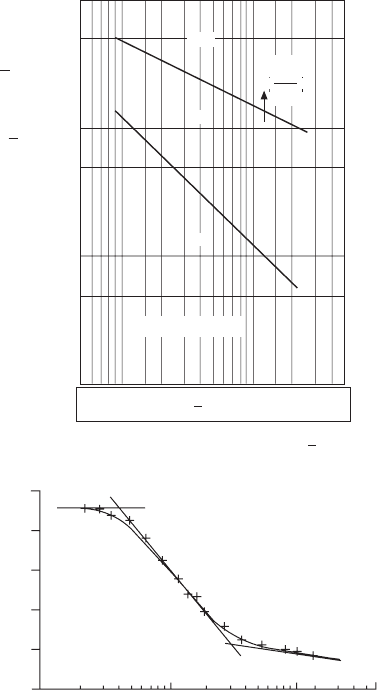
contact pressure is increased. Schipper et al. (1991) provided the rules (Fig.
10.4) of the lubrication parameter as a function of the contact pressure for
the regime transitions. With these rules it is possible to predict in which
lubrication regime a particular lubricated concentrated contact operates.
Schipper and de Gee (1995) further concluded that the transition from
the elastohydrodynamic to the mixed lubrication takes place at
s
m
sr
lm
ea
n
v
p
v
15
05
5
65
10
.
15.15
,
lm,lm
.
05.05
.
65.65
=
¥
-
10.22
and the transition from the mixed to the boundary lubrication takes place
at
s
m
s
v
v
= 1.6
¥
-
10
5
10.23
where v is the mean rolling speed (m/s) and m
v
is the inlet viscosity (Pa.s).
For a rolling contact (e.g., a tappet roller on a cam), the rolling friction
coef cient (usually in the range of 0.001–0.003) is much lower than the
sliding friction coef cient (e.g., 0.1 in boundary lubrication). The rolling
friction coef cient actually rises with the l ratio (Spikes, 1997).
The experimental coef cients of friction for the light-duty and heavy-
duty engine bearings were reported by Kapadia et al. (2007). In their work,
Diesel-Xin-10.indd 667 5/5/11 12:00:26 PM
668 Diesel engine system design
© Woodhead Publishing Limited, 2011
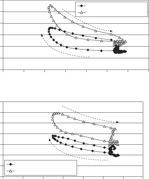
they also reported the measurement of friction forces vs. calculated l ratio
at different engine speeds and loads (Fig. 10.5).
The fundamentals of hydrodynamic lubrication are introduced in numerous
books (e.g., Cameron, 1981; Heywood, 1988; Taylor, 1993a). The analysis
of thick- lm hydrodynamic lubrication for engine bearings is reviewed by
Tanaka (1999). Thin- lm lubrication and wear is reviewed by Jacobson
(1997). Mixed lubrication is reviewed by Spikes (1997). The fundamentals
10.4 Use of a lubrication parameter to characterize lubrication regime
transitions (from Schipper et al., 1991 and Schipper and de Gee,
1995).
EHL—ML:
HRa
t
1.5
=
3.1 ¥ 10
4
p
–0.5
ML—BL:
HRa
t
1.5
=
1.25 ¥ 10
4
p
–0.5
10
–3
5
3
2
10
–4
5
3
2
10
–5
5
3
2
10
–6
EHL
ML
BL
Ra
t
= 2.5 ¥ 10
–8
m
5 10
–3
2 3 5 10
–9
2 3 5
p/[Pa]
(a) Lubrication parameter (H/Ra
t
= L) as a
function of mean contact pressure (p) (from
Schipper et al., 1991)
(b) Experimental friction speed diagram for a
concentrated contact (from Schipper and de
Gee, 1995)
10
–5
10
–4
10
–3
Lubrication number L
Coeffi cient of friction
0.125
0.100
0.075
0.050
0.025
0.000
BL
ML
EHL
Ra
Ra
t
o
0.
5
5
È
Î
Í
È
Í
È
Î
Í
Î
˘
˚
˙
˘
˙
˘
˚
˙
˚
Diesel-Xin-10.indd 668 5/5/11 12:00:26 PM
669Friction and lubrication in diesel engine system design
© Woodhead Publishing Limited, 2011
on the boundary lubrication and scufng are introduced in Ling et al. (1969),
Spikes (1995), Taylor (1993a), and Ludema (1984).
10.2.4 Surface topography
Surface topography refers to both the prole shape and the surface roughness
(including the waviness and the asperity or the nish). Surface topography
affects the lm thickness to roughness ratio and the lubrication regime. In
the thin-lm hydrodynamic or mixed lubrication calculations, the inuence of
surface roughness on the lubricating oil lm thickness and pressure distribution
obtained by solving the Reynolds equation is not negligible. The orientations
0 1 2 3 4 5 6 7
Lamda value
0 0.5 1 1.5 2 2.5 3 3.5
Lamda Value
(a) Friction force versus lambda ratio for 15W-40 low-viscosity oil
using the PCMO bearing set-up.
(b) Friction force versus lambda ratio for 15W-40 low-viscosity
oil using the HDD bearing set-up.
Decrease in loading cycle
Decrease in loading cycle
Increase in loading cycle
Increase in loading cycle
Friction force at 700 rpm
Friction force at 1400 rpm
Friction force at 700 rpm
Friction force at 1400 rpm
Friction force
Friction force
30
25
20
15
10
5
0
35
30
25
20
15
10
5
0
10.5 Measured friction force vs. the lambda ratio for LD and HD
engines (from Kapadia et al., 2007).
Diesel-Xin-10.indd 669 5/5/11 12:00:27 PM