Water and Wastewater Engineering
Подождите немного. Документ загружается.

13-28 WATER AND WASTEWATER ENGINEERING
A mmonia is available commercially in three forms: anhydrous ammonia (liquified gas), aque-
ous ammonia (NH
3
dissolved in water NH
4
OH), and ammonia sulfate crystals. Anhydrous am-
monia and aqueous ammonia are the forms most commonly used. With minor modification, the
equipment used to feed anhydrous ammonia is the same as that used for chlorine. Although anhy-
drou
s ammonia injector systems are available, direct ammonia gas feeder designs are common.
Aqueous ammonia is commercially available as a 19 percent by weight solution. Diaphragm
metering pumps are used to deliver aqueous ammonia. The recommended piping is carbon or
stainless steel. Be
cause it reacts violently with copper, brass, bronze, or other copper alloys, they
must not be used in the aqueous ammonia feed system. Ammonia vapors are extremely toxic and
appropriate venting must be supplied.
A few of GLUMRB’s (2003) recommended safety precautions for aqueous amm
onia (also
called aqua ammonia) are as follows:
• A closed unpressurized tank with lockout provisions to prevent accidental addition of
incompatible chemicals shall be provided for storage. It shall be vented through an inert
liquid trap to a high point outside.
• The storage tank shall be fitted with either cooling/refrigeration and/or provision for adding
dilu
tion water without opening to prevent ammonia vapor pressure from exceeding atmo-
spheric pressure.
• An exhaust fan shall be installed to withdraw air from high points in the room and makeup
air shall be allowed to enter at a low point in the room.
A scrubber system that is activated in the vent of an ammonia leak is recommended. Section
80.303 of Article 80 of the Uniform Fire Co
de provides design guidance.
For anhydrous ammonia, GLUMRB (2003) recommends safety precautions similar to those
specified for chlorine gas. Two notable exceptions are that the air exhaust system shall have an
elevated intake and that heaters shall be provided. The complete list of GLUMRB (2003) reco
m-
mendations should be consulted for design compliance.
Operator Safety. Operators should have Occupational and Safety Administration (OSHA)
training on the use of personal protective euipment (PPE). Provisions for PPE and safety equip-
ment include the following (GLUMRB, 2003):
• Full face mask (gas mask) res
piratory protection equipment that meets the requirements
of the National Institute for Occupational Safety and Health (NIOSH) shall be available
but not stored inside any room where gaseous chemicals are used or stored. The units
shall use compressed air and have at least a 30 minute c apacity
. These units are termed
self-contained breathing apparatus (SCBA).
• Continuous leak detection equipment with an audible alarm and warning light is
recommended.
• A deluge shower and eyewash should be installed in the room where disinfection chemicals
are used or stored.
• E a
ch operator shall be provided with appropriate protective clothing including rubber gloves,
face shields, and rubber aprons appropriate for the chemicals being handled.

DISINFECTION AND FLUORIDATION 13-29
The American Water Works Association Manual of Practice M20 (AWWA, 2006) provides de-
tailed recommendations for evaluating safety equipment and the appropriate personal protective
equipment (PPE) for tasks involving potential exposure to chlorine compounds.
Sources of Ultraviolet Radiation. Both low-pressure and medium-pressure lamps are avail-
able for disinfe
ction applications. Low-pressure lamps emit their maximum energy output at
a wavelength of 253.7 nm, while medium-pressure lamps emit energy with wavelengths rang-
ing from 180 to 1370 nm. The intensity of medium-pressure lamps is much greater than low-
pressure lamps. Thus, fewer medium
-pressure lamps are required for an equivalent dosage.
For small systems, the medium-pressu re system may consist of a single lamp. Although both
types of lamps work equally well for inactivation of organisms, low-pressure UV lamps are
recommended for small s ystems be
cause of the reliability associated with multiple low-pres-
sure lamps (U.S. EPA, 1996).
Contact Facilities. The Chick-Watson law provides the theoretical basis for the EPA’s ap-
proach to regulation of drinking water disinfection, that is, the provision of adequate chemical
dose and contact time ( Ct ). Prior to the recognition and regulation of THMs , adequate contact
ti
me was provided by addition of the primary disinfectant early in the treatment process.
Since 1980, when the EPA began to regulate THM, many existing and newly proposed facili-
ties locate the point of addition at the end of the process. This is the approach that will be
discussed here.
The disinfection reactors, also called disi
nfection chambers or contact chambers, fall
into three categories: pipelines, longitudinal-serpentine basins, and cross-baffled serpentine
basins. The ideal reactor for chlorine, combined chlorine, and chlorine diox ide is one that
exhibits ideal plug-flow, that is, one with no longitudinal dispersion so that the contact time
is equal to the hydrauli
c residence time. The gases Cl
2
, NH
3
, and ClO
2
are metered into a
slip stream (a portion of the water that has undergone coagulation, settling, filtration, or other
treatment) that is then injected into the main flow of water passing into the contact chamber.
A long pipeline, preferably without bends and restrictions, provides the most ideal reactor.
For example, a pipeline that provides 30 minutes of contact time at a flow rate greater than
0.044 m
3
/ s and a velocity greater than 0.6 m/s will be nearly ideal, that is, a pipeline abou t
1 km long (MWH, 2005). Unfortunately, real pipelines generally reach the first customer
through a much shorter distance with a less than ideal flow path. However, for that portion
of the line that approaches the ideal setting, calculation of the dispersion number provides
an estimate of the performance of the reac tor. The dis
persion number may be estimated as
(Sjenitzer, 1958):
df
D
L
#
89 500
3 6
0859
,
.
.
⎛
⎝
⎞
⎠
(13-30)
where d
#
dispersion number, dimensionless
f Darcy-Weisbach friction factor, unitless
D diameter of pipe, m
L length of pipe, m
13-30 WATER AND WASTEWATER ENGINEERING
A goal of the pipeline design is a dispersion number of about 0.01. Lower dispersion numbers
add little increase in kill efficiency, while dispersion numbers above about 0.05 drop off rapidly
in kill efficiency (Trussell and Chao, 1977).
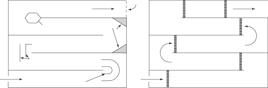
In the absence of a suitable long pipeline, a longitudinal-serpentine basin is generally
the most cost-effective
means of providing a contact chamber approaching ideal plug flow
(MWH, 2005). Because the serpentine flow results in flow separation and dead spots as a
result of the 180 flow reversal, the alternative devices shown in Figure 13-10 have been
proposed to correct these problems. Marske and Boyle (1973) recommend a mini
mum length
to width ratio of at least 40:1. It is measured as the width of the flow path to the length of
the flow path. In addition, they recommend a sharp crested weir the width of the flow path
at the end of the chamber. Height-of-channel to width-of-channel ratios are generally in the
range of 1 to 3.
Because no reactor provides ideal plu g flow, the contact time is generally less than
ideal. To account for nonideal reactors, EPA has adopted a requirement that the Ct value be
calculated with the time that 90 percent of the water will be exposed in the disinfection
chamber. This time is called t
10
(U.S. EPA, 1991). Although tracer studies are recommended
to determine t
10
for design, an alternative approach using a baffling classification system is
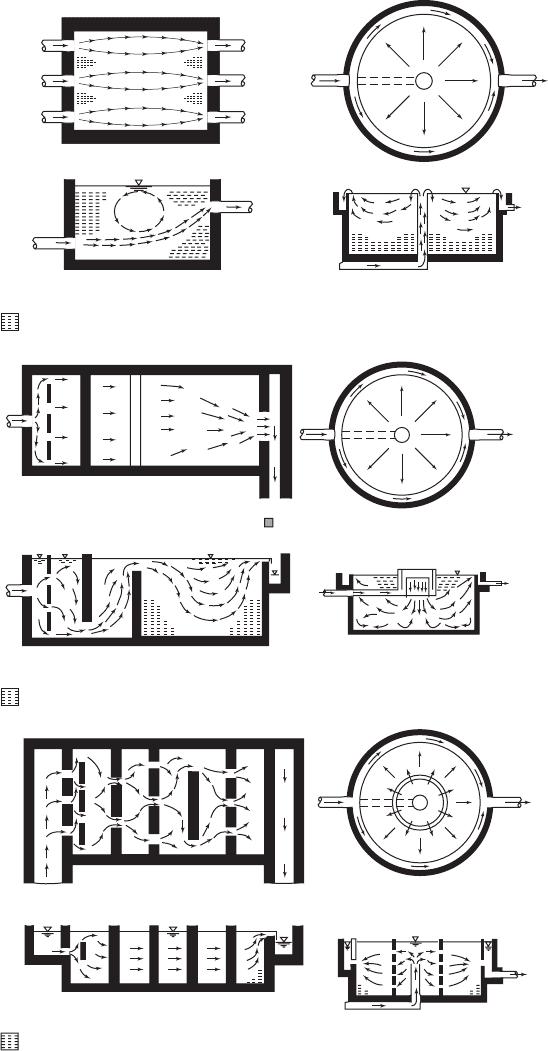
provided . Examples of the various baffle classifications are shown in Figure 13-11 . EPA’s
assumed ratio of t
10
to the theoretical hydraulic detention time ( t
0
) for each of the classi-
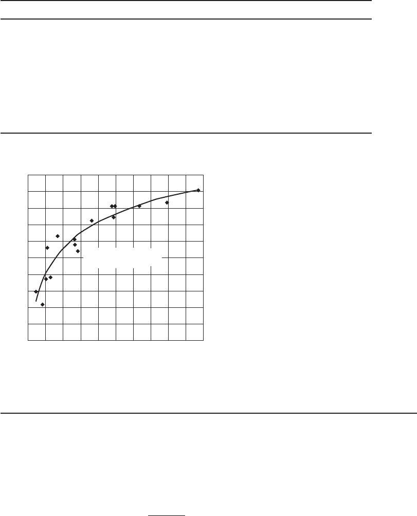
fications is given in Table 13-8 . Figure 13-12 shows the effect of L:W ratio on the t
10
/ t
0
ratio. The use of the baffle classifications in the design of a contact chamber is illustrated in
Example 13-7 .
Inlet diffuser wall
Outlet diffuster
baffle
Diffuser wall at
beginning of each pass
Semicircular turning vanes
(a) (b)
Hammerhead
Fillets
Full width
sharp crested weir
Turning vanes
FIGURE 13-10
Controlling flow separation in serpentine basins using various devices.
Note: Do not put in diffuser wall before a turn or halfway through a turn.
DISINFECTION AND FLUORIDATION 13-31
Plan
Plan
Section
Circular contact basin
Section
Rectangular contact basin
Plan Plan
Plan
Section
Rectangular contact basin
Potential dead zone
Plan
Section
Circular contact basin
Section
Circular contact basin
Section
Rectangular contact basin
Potential dead zone
(b)
(a)
Potential d
ead zone
(c)
FIGURE 13-11
Baffling condition examples.
( a ) Poor baffling, ( b ) average
baffling, ( c ) superior baffling.
( Source: U.S. EPA, 1991.)
13-32 WATER AND WASTEWATER ENGINEERING
Example 13-7. Design a longitudinal-serpentine chlorine contact chamber for a design flow of
18,400 m
3
/ d. The required t
10
to achieve a Ct of 200 is 100 min. The design must provide supe-
rior performance, that is t
10
/ t
0
0.7.
Solution:
a . Calculate the required hydraulic detention time.
100
07
142 86 145
0
0
min
or about min
t
t
.
.
Performance
t
10
/t
0
Baffling description
Very poor 0.1 Unbaffled (mixed flow), agitated, very low length-
to-width ratio, high inlet and outlet flow velocities
Poor 0.3 Single or multiple unbaffled inlets and outlets, no
intrabasin baffles
Average 0.5 Baffled inlet or outlet with some intrabasin baffles
Superior 0.7 Perforated inlet baffle, serpentine or perforated
intrabasin baffles, outlet weir or perforated launders
Perfect 1.0 Very high length-to-width ratio (pipeline flow),
perforated inlet, ou
tlet, and intrabasin baffles
TABLE 13-8
Baffle classification
Source: Adapted from U.S. EPA, 1991.
y 0.2163Ln(x)0.0827
R
2
0.8733
t
10
/t
0
0
0.0
0.1
0.2
0.3
0.4
0.5
0.6
0.7
0.8
0.9
1.0
2010 304050
L/W
60 70 80 90 100
FIGURE 13-12
I mpact of L/W on t
10
/ t
0
ratio.
Source: Crozes et al., 1999.
DISINFECTION AND FLUORIDATION 13-33
b. From the definition of hydraulic detention time, the volume of the reactor is then
t
Q
tQ
0
0
3
145 18 400
1
1 440
()() ( )( )min m /d,
,
min/d
m
⎛
⎝
⎜
⎞
⎠
⎟
185278
3
.
V
V
V
c. As recommended, assume a value for L 40 W and H 3W. Using Figure 13-3 at
t
10
/ t
0
0.7, find L:W is a little less than 40:1. Therefore, select L:W 40:1.
L
H
W
=
=
40
3
W
W
width of channel
d . Solve for the width of the channel:
WW W
W
()( )( )3 40120
120
1852
3
1 3
1 3
/
/
W
⎛
⎝
⎞
⎠
.
778
120
2.49 or 2.5 m
3
m
⎛
⎝
⎜
⎞
⎠
⎟
V
V
e . The channel dimensions are then
L
H
W
40 2 5 100
3 27
2
()
()
.
.5 .5
.5
mm
mm
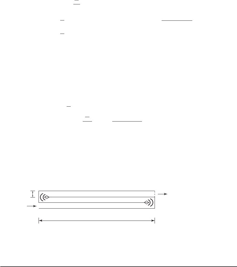
f . A sketch of the contact chamber plan with devices to control flow s eparation is shown
below.
2.5 m
33.3 m
Comment:
1 . For ease of construction, the dimensions would be 100 m 7.5 m 2.5 m. This pro-
vides a volume of 1,875 m
3
, which is greater than the 1,852.78 m
3
required.
2. To meet redundancy requirements, two contact chambers of this size must be provided.
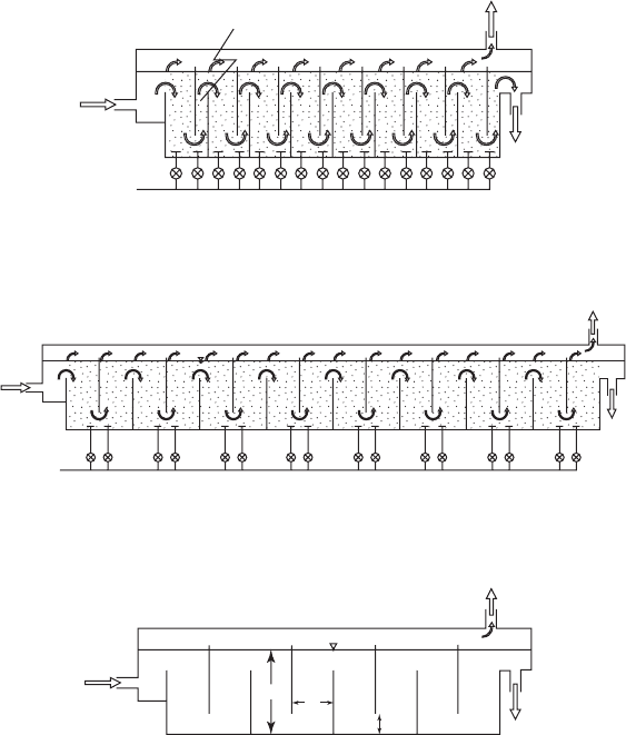
When ozone is bubbled into the contact chamber rather than a slip stream, a cross-baffled
serpentine chamber is used ( Figure 13-13 ). The nu mber and size of the
cells depends on the
ozonation objective. For oxidation only (no disinfection), two or four cells are used. For disinfec-
tion to achieve Giardia and virus inactivation, six or eight cells are common. Cryptosporidium
inactivation calls for 10 or more cells (Rakness, 2005). Normal operation is to us
e diffusers in
13-34 WATER AND WASTEWATER ENGINEERING
the first cell of contact chamber as shown in the figure. However, if the initial diffusers cannot
meet the ozone demand, then the piping system is designed with the ability to place diffusers in
several cells or, in the extreme, in every cell. This allows for ozone injection to maintain the re-
quired concentration, C, at the desired level. Pilot s
cale testing is used to determine the need for
diffusers in more than one cell. Porous diffusers that provide fine bubbles provide a higher ozone
transfer efficiency than perforated pipe. Using computational fluid dynamic (CFD) modeling,
Henry and Freeman (1996) found that the ratio of fluid depth (H) to the longitud
inal width (W)
and the ratio of the depth of the opening under the baffle to the longitudinal width can be used to
maximize the t
10
/ t
0
ratio. Their work showed that at H:L 4:1 and W:L 1:1, a t
10
/ t
0
ratio of
0.65 was achieved. H ranged from 6 to 7.5 m.
I deally the dose and contact time for ozonation is determined from bench and/or pilot scale
data using actual raw water samples. Although the maximum practical concentration of ozone in
Off–gas to ozone
destruct units
Effluent
water
Chimney
Influent
water
Ozone rich gas from
ozone generator
Off–gas to ozone
destruct units
Effluen
t
water
Off–gas to ozone
destruct units
Effluent
water
(b)
(c)
(a)
Ozone rich gas from
ozone generator
Influent
water
Influent
water
L
h
H
FIGURE 13-13
S chematics cross-sectional views of two alternate designs for an eight-chamber, over-under contact
chamber: ( a ) with chimneys and ( b ) without chimneys. Figure ( c ) provides dimension definitions.
DISINFECTION AND FLUORIDATION 13-35
solution is 40 mg/L (U.S. EPA, 1986), normal dose values are less than 10 mg/L for drinking wa-
ter applications. Ozone gas transfer rates are on the order of 85 percent for air-fed ozone systems
and 95 percent for liquid oxygen-fed systems. Thus, for a 10 mg/L dose, the transferred dose will
be on the order of 8.5 to 9.5 mg/L.
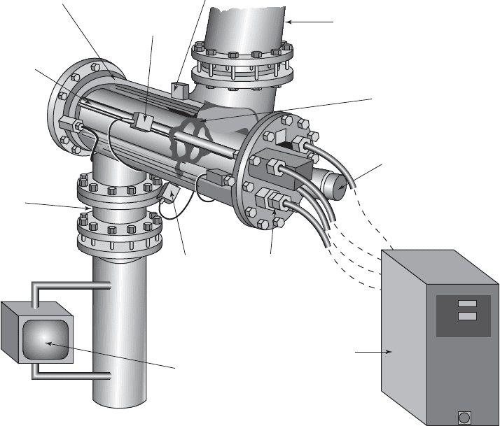
Most conventional UV rea
ctors are available in two types: closed vessel and open channel.
For drinking water applications, the closed vessel is generally the preferred UV reactor for the
following reasons (U.S. EPA, 1996):
• S maller footprint.
• Minimized pollution from airborne material.
• Minimal personnel exposure to UV.
• Modular design for installation simplicity.
Figure 13-14
shows a conventional closed-vessel UV reactor.
UV lamp housed with
UV lamp sleeve
Reactor
casing
UV intensity
sensor
Temperature
sensor
Effluent
pipe
Lamp sleeve
wiper
Wiper
motor
Electrical
connection
to lamp
Control
panel
UV intensity
sensor
UV
transmittance
monitor
Influent
pipe
FIGURE 13-14
UV disinfection system schematic. ( Source: Aquionics.)
13-36 WATER AND WASTEWATER ENGINEERING
Ballasts (i.e., transformers) that control the power of the UV lamps are either electronic or
electromagnetic. Electronic ballasts offer several potential advantages including lower lamp op-
erating temperatures, higher efficiencies, and longer ballast life.
The equation for UV dose indicates that dose is directly proportional to exposure time and
th
us inversely proportional to system flow rate. UV intensity ( I ) is a function of water UV trans-
mittance and UV reactor geometry as well as lamp age and fouling. UV intensity can be esti-
mated by mathematical modeling and verified by bioassay. Exposure time is estimated from the
UV rea
ctor specific hydraulic characteristics and flow patterns.
The major factor affecting the performance of UV disinfection systems is the influent water
quality. Particles, turbidity, and suspended solids c an shield pathogens from UV light or scatter
UV light to prevent it from reac
hing the target microorganism, thus reducing its effectiveness as
a disinfectant. Some organic compounds and inorganic compounds (such as iron and perman-
ganate) can reduce UV transmittance by absorbing UV energy or coating the lamps. When this
occurs, higher levels of UV are required to achieve the sam
e dose. Therefore, it is recommended
that UV systems be installed downstream of the filters so that rem oval of particles and organic
and inorganic compounds is maximized upstream of UV.
Water turbidity and UV transmittance are commonly used as pro
cess controls at UV facilities.
The UV percent transmittance of a water sample is measured by a UV-range spectrophotometer
set at a wavelength of 253.7 nm using a 1-cm-thick layer of water. The water UV transmittance
is related to UV absorbance (A) at the same wavelength by the equation:
Percent transmittance
100 10%
A
(13-31)
For example, a water UV absorbance of 0.022 per cm corresponds to a water percent trans-
mittance of 95 (i.e., at 1 cm from the UV lamp, 95 percent of lamp output remains). Similarly, a
UV absorbance of 0.046 per cm is equivalent to 90 percent UV transmittance.
EPA’s Ct Tables. The EPA’s tables (Code of Federal Regulations, 40 CFR 141.74 and 40 CFR
720) provi
de the simplest approach for establishing a design strategy for disinfection. The tables
are provided in Appendix D . The tables set disinfection credits for Giardia, Cryptosporidium, and
viruses when chlorine, chloramine, chlorine dioxide, ozone, or UV is used. Water temperature an
d
pH are addressed in the tables.
Chlorine Dose Guidance. Michigan’s rules for chlorine residuals provide guidance on dosage.
They require that the minimum free chlorine residual at active points in a water distribution system
be 0.2 to 0.5 mg/L and that combined chlorine residuals be 1.0 to 2.0 mg/L. The r
ules also suggest
that it is desirable to have a trace of free chlorine at distant points in the distribution system.
Disinfection Design
Ultimately the agency that administers drinking water regulations will determine the required Ct
requirements and the credits that will be given for variou s treatment steps. The following steps
can be taken to determine the probable credits (adapted from Hesby, 2005):
1 . Determine the total removal/inactivation required.
• Tables 13-4 and 1
3-9 provide guidance for standard removal/inactivation credits.
• For vulnerable sources, higher removal/inactivation may be required ( Table 13-5 ).

DISINFECTION AND FLUORIDATION 13-37
2. Determine the credits for physical removal.
• Table 13-10 provides guidance for standard treatment credits.
3. Determine the credits required for inactivation by disinfection.
• The difference between the removal/inactivation required and the physical removal
credits is the requ
ired inactivation.
4. Select the disinfectant.
• U sing the boundary conditions (TOC, AOC, DBPFP, and distribution detention time),
select the primary and secondary disinfectant.
5. Determine the required Ct to achieve the required inactivation for the design conditions
(pH, temperat
ure).
6. Compute t
10
for the water to reach the first customer.
7. Compute the Ct credit at the first customer and the credit required for the contact cham-
ber.
8. Establish the contact chamber’s hydraulic efficiency using Figure 13-11 or Figure 13-12
and find t
10
/ t
0
from Table 13-8 or Figure 13-12 .
9. Compute the required hydraulic detention time ( t
0
).
10. Design the contact chamber.
11. Iterate the design for alternate disinfectants, contact times, temperatures, flow rates, and
pH values.
E xample 13-8 illustrates the design process through step 9.
TABLE 13-9
Log-removal/inactivation requirements for filtered water
Microorganism Log removal/inactivation Remarks
Giardia cysts
3
Viruses 4
Cryptosporidium oocysts
0 to 2.5 See Table 13-4
Log removal credit
Process Giardia cysts Viruses
Cryptosporidium
oocysts
Conventional filtration plants 2.5 2 3
Direct filtration plants 212.5
TABLE 13-10
Standard log-removal credits for treatment