Water and Wastewater Engineering
Подождите немного. Документ загружается.


28-24 WATER AND WASTEWATER ENGINEERING
PARCC Side Clean Water Plant performance
Parameter
Average daily effluent
concentration
a
NPDES winter limits Comment
BOD
5
< 2 40 7 day maximum
25 Monthly maximum
TSS < 2 45 7 day maximum
30 Monthly maximum
NH
4
+
-N 0.1 to 3 N/A
N/A
P < 0.5
a
January and February.
Units are all mg/L, N/A there are no winter limits.
The state-of-the-art features of the plant include:
• MBR process.
• Fine screens (1 mm) without a coarse prescreen.
• Elimination of primary and secondary settling tanks.
• Inclined screw press.
• Integrated odor control.
• Environmentally compatible architecture.
Comments:
1 . As with all plant start-ups, it took abou
t two months for the biological process to accli-
mate and begin functioning as planned. In this instance, this period was at the start of
winter conditions in Michigan (November–December). This proved to be an extremely
challenging period of time for the newly formed operating staff. The membranes were
very beneficial in this period as the effluent permit require
ments were consistently met.
2. There were operational problems with the fine screens. The 1.0 mm fine screens were
replaced with 1.5 mm screens. This, coupled with modification of the influent distribu-
tion systems, appears to have resolved the problems.
3. The capital cost of the plant is about 10 percent higher than it would
have been for a
conventional plant.
4. The Authority is composed of four townships and one city. The plant was named using
the initials from each of the five Authority members (Plainfield, Alpine, Rockford, Can-
non, and Courtland). There is a county park between the plant and the Grand River. In this
context, the name PARCC Side Clean Water Plant appealed to the Authority member
s.
28-3 SIMULATION MODELING
S i mulation software that was developed originally and used predominantly by res earchers on
mainframe computers has now become routinely available for consultants and operators to run on
their own personal computers. Although it is relatively simple to construct and run a model with
CLEAN WATER PLANT PROCESS SELECTION AND INTEGRATION 28-25
current software, learning which parameters to adjust and how the results should be interpreted or
applied requires a substantial time investment. Nonetheless, the simulator packages are powerful
tools both for process selection and process integration.
The simulators have a library of process scenarios with ad justable defa
ult values for model
parameters. Current simulators use “Activated Sludge Model No. 3” also known as ASM3 (Gujer
et al., 1999). Some typical model scenarios include carbonaceous BOD removal and nitrification,
nitrification/denitrification, and carbon-nitrogen-phosphorus removal. Preconfigured la
youts are
provided. Some examples include conventional activated sludge, oxidation ditch, SBR, IFAS,
and MBR. Alternatively, users can assemble their own plant.
Because the simulators allow the user to change almost all parameters used in the models,
they can be use
d to test a wide range of process configurations and situations. The common use
of a model is to make one or more “virtual” designs. Different scenarios can then be run virtually
side by side to determine which approach works best.
The models can also be used as
design tools. They can help to answer such questions as
“How many aeration basins are required?” They can be used to perform sensitivity analysis to
optimize the design of parameters such as recycle flow rates.
The models are not foolproof. They do not include any of the safety factor
s commonly used in
the design and operation of facilities. The accuracy of a model is highly dependent on the data used
to develop it. “Garbage in garbage out” still applies regardless of the sophistication of the model.
Adjustment of several parameters simultaneously may yield i
mpressive results that cannot be achieved
in a real plant. Realistic application of the simulations requires calibration of the model. While this
may be possible for an upgrade or retrofit, for a new plant in a new situation, this is impractical.
The general outline for good modeling practice is (Shaw et al., 2007):
• Define what is to be done with the model.
• Collect data regarding tank sizes and
configuration, flows, waste characteristics, and solids
quantities.
• Set up the model.
• Calibrate the model by matching outputs to measured data, and validate the model by
checking how it behaves under different conditions with a different set of data.
• Use the mod
el.
The North American market for wastewater process simulators is dominated by Biowin
®
,
which is made by Envirosim Associates LTD (Flamborough, Ontario), and GPS-X
®
, a product of
Hydromantis, Inc. (Hamilton, Ontario).
28-4 PROCESS INTEGRATION
Plant Layout
The discussion on plant layout for drinking water plants in Chapter 16 applies equally well for clean
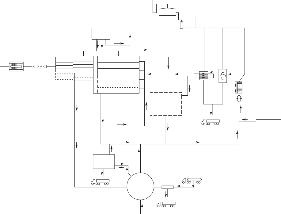
water plants. It will not be repeated here. The PARCC Side Clean Water Plant ( Figure 28-4 ) is an
example of the plant layout of a state-of-the-art membrane bioreactor. The schematic of the plant
shows the relationship of the process components and their interconnections. The highlights of this
plan are the absence of primary and se
condary clarifiers, the use of fine screens, the designation of
space for future expansion, and the prominence of the odor collection system and biofilter.
28-26 WATER AND WASTEWATER ENGINEERING
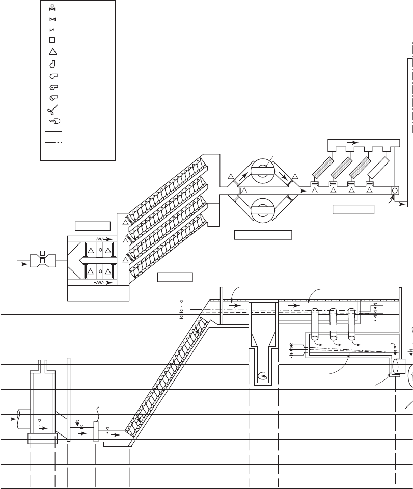
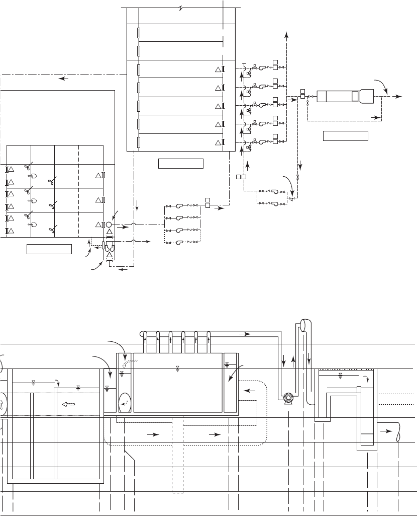
Plant Hydraulics
Plant hydraulics are represented by a drawing that shows the hydraulic grade line across the treat-
ment plant. The drawing should show the elevations of the walkway (top of the structure), the water
levels, the bottom elevation of each unit process as well as the invert and crown of all connecting
pipes and the invert of all channels. An example hydraulic profile is
shown in Figure 28-5 .
I deally, the water flows through the plant by gravity after it is pumped to the head end of
the plant. This minimizes the number of pumps to move the water through the plant. The eleva-
tion of the surface of the water as it flows throu gh the plant follows the hydraulic grade line.
These elevations are set by the design based on calculations of headloss
through the various
structures of the plant. Once the headlosses are known, the elevations of the surface water are set
Casgade
aeration
River discharge
Ultraviolet
disinfection
Membranes
Blowers
To aerobic
storage
RAW
Biofilter
Discharge
From solids
Grit
chamber
Screening
Screw
pumps
Wastewater
To landfill
Future
equallization
basin
Solids
handling
Aerobic
biosolids
storage
To landfill
To landfill
Septage
From
blowers
Future
septage
receiving
(Future)
(Future)
Bioreactor
s
Chambers
Prehumidifer
Supernatant
WAS/RAS
WAS
EQ/DRAIN
RAS
Raw
FIGURE 28-4
Process schematic of PARCC Side Clean Water Plant.

CLEAN WATER PLANT PROCESS SELECTION AND INTEGRATION 28-27
by working upstream from a selected elevation for the effluent discharge to the influent to the
plant. The elevation of the water surface in each process upstream is set to overcome the headloss
in moving the water to the next downstream process.
Some of the headloss calculations have already been demonstrated. These are listed in
Table 28-1
5 .
T ypical headlosses in clean water plants are given in Table 28-16 .
Clean water plant headloss calculations must include return flows from the biological
processes. While return activated sludge (RAS) flows may equal 100 to 150 percent of the influ-
ent flow in conventional activated sludge plant, the RAS in a membrane bioreactor (MBR) plant
will be on the order of 400 per
cent of the influent flow. In extremely high flow conditions, the
MBR system may need to recycle a much greater percentage of the influent flow.
Hydraulic Loading Variability. Almost all the kinetic and empiric al factors used in design
are based on constant wastewater flow rate and loading conditions. In practice, the flow rates
and loadings vary. Table 28-17 i
dentifies some of the hydraulic design and sizing criteria for
suspended growth secondary treatment facilities. Other loading factors are discussed in the next
section of this chapter.
TABLE 28-15
Summary of locations of headloss estimation calculations
Source of headloss Chapter reference
Baffles 6
Bar racks and screens 20
Channels 16
Grit chambers 20
Granular filtration 11
Pipe, sludge 20
Pipe, water 3
TABLE 28-16
Typical clean water plant headlosses
Treatment unit Range of headloss, m
Bar screen 0.15–0.30
Grit chambers
Aerated
0.4–1.2
Vortex
0.15
Primary sedimentation 0.4–1
Aeration tank 0.2–0.6
Secondary sedimentation 0.4–1.2
Granular filtration 3–5
Carbon adsorption 3–6
Chlorine contact tank 0.2–1.88
UV contact tank 0.6
A dapted from Metcalf & Eddy, 1991.
28-28 WATER AND WASTEWATER ENGINEERING
FIGURE 28-5
H ydraulic profile of PARCC Side Clean Water Plant.
6
2
Channel
54” RAS pipe
Influent
flume
chamber
Macerators
C2
C1
7777
64
5
Screen inlet channel
Screen outlet channel
Overflow
Screen System
GRIT Removal System
Screw Pumps
Macerators
H E A D W O R K S
36"
Bioreactor distribution channel
S1
S2
S3
Fu
ture S4
Bypass channel
Future GRIT
chamber GCI
GRIT chamber
GCI
Paddle drive
GP1
SP1
SP2
SP3
SP4
Screen pump
outfall
channel
Screen pump
inlet
channel
Fu
t
u
re
s
c
rew
p
u
m
p
SP4
M
1
48"
635.67
635.42
634.17
628.5
628.0
627.5
Grit
Chamber
Future communitor channel
Overflow
Overflow
Influent flume
chamber
48”
48”
613.0
613.4
611.8
612.3
48” Inlet
48” Outlet
Comminutor
48” Comminutor Inlet
Screw pump inlet
Inv. EL. 608’–6’
Inv. EL. 610’–0’
Inv. EL. 610’–6’
Inv. EL. 612’–0’
Inv. EL. 611’–8 1/2’
36”
3
3
12
1
2
3
Screw pump
outfall
channel
Screen inlet
channel
Screen outlet
channel
Screen inlet
channel
overflow
M
Control valuve
Isolation valve
Order valve
Flow metor
Gate
Submersible pump
Pump
Air handler
Blower
Meter
Reorculation pump
Prop. wastewater
Prop. RAS pipe
Prop. water pipe
L E G E N D
635
630
625
620
615
610
605
600
Screens
CLEAN WATER PLANT PROCESS SELECTION AND INTEGRATION 28-29
Membrane Tank
630.0
629.0
625.0
626.0
627.0
2
7.5
RAS collection
Collection
Bioreactor
collection
channel
Bioreactor
distribution
channel
Bioreactor Tank
54” RAS
RAS
pump
54” RAS
Aerobic
zone 1
Aerobic
zone 2
Swing
zone
Anoxic
zone 1
Bioreactor Tank
Inv. EL. 521’–0’
BIoreactor Tank
Channel
Inv. EL. 08’–3’
Channel
Channel
54” Ras pipe
Inv. EL. 614”– 3”
Inv. EL. 621”- 0”
Inv. EL. 521”- 0”
Inv. EL.608”- 0”
30”
10”
48”
30.5”
Membrane Tank
Collection Channel
Permeate pump
12”
628.5
500 year
500 year Flood El. 624.8
100 year Flood El. 621.8
Auto. Level Controller
El. 626.33
El. 626.3
8 MGO
normal
EL.616.42
Inv. EL. 624”- 0”
Inv. EL. 623”– 6”
Inv. EL. 621”– 0”
Inv. EL. 637”– 6’
Inv. EL. 614”– 0”
Inv. EL. 615”– 0”
Inv. EL. 603”– 4”
Inv. EL. 622”– 6’
Inv. EL. 620” – 3”
Permeate Pump
30” Permeate Pipe
U.V Rise Well
U.V Outfall Well
48” Outlet @ River
48” Outlet
30“ U.V Inlet
48” RAS pipe
9
8
10
10
10
12
11
9
8
9
8
RP1
RP2
RP3
M21
M32
M22
M12
M31
M11
Bioreactor tank 1
Bioreactor tank 2
Bioreactor tank 3
To
biosolids
storage
Overflow
WAS/
wet well
RAS1
RAS pumps
RAS2
RAS3
Future
RAS4
PP5
Bioreactor collection channel
13
13
13
13
13
RAS
intake
WAS pumps
54” RAS
Outlet
weir
Outlet
weir
Outlet
weir
Outlet
weir
Outlet
weir
Outlet
weir
Outlet
weir
RAS collection channel
Membrane distribution channel
Bulkhead
Bulkhead
Membrane tank 1
Membrane tank 2
Membrane tank 3
Membrane tank 4
Membrane tank 5
Membrane tank 6
(No internals)
Membrane tank 7
(No internals)
Future membrane tanks 6 & 8
Membrane Tanks
Bioreactor Tanks
UV Disinfection
M
7
12"
PP4
M
7
M
2
12"
PP3
M
7
12"
PP2
M
7
12"
PP1
M
7
8
12"
54" RAS recirculation
30"
24" Ultraviolet disinfection system bypass
12"
16"
8"
CIP2
CIP1
CIP/Backpulse pumps
Strainer
48" Outfall piping
To plant
water system
Rise
well
Outfall
well
U.V. lamp banks
ALC
M
M
6
48" RAS
Anoxic zone 1 Aerobic zone 1 Aerobic zone 2Swing zone
Future bioreactor pumps 4, 5, & 6
Bioreactor distribution channel
MACHINE BUILDING
635
630
625
620
615
610
605
600
FIGURE 28-5 (continued)

28-30 WATER AND WASTEWATER ENGINEERING
Mass Balances
In conc eptual design, mass balances provide an analytical tool for comparing alternatives. In
detailed design, mass balances provide a standard frame of reference for consistent use of design
criteria and quantity estimates. The mass balances also provide a basis for the
control logic of the
process and instrumentation diagrams. Typically, mass balances are calculated for the following
constituents: suspended solids, BOD, COD, nitrogen (as N), alkalinity, and phosphorus (as P).
The reader is referred to Introduction to Environmental Engineering (Davis and Cornwell,
2008) for a general introduction to the ma
ss balance technique. An introduction to solids mass
balance is given in Chapter 27 of this text.
Process Loading Variability. One aspect of a mass balance analysis is the investigation of the
impact of changes in process loading. In the absence of on-site field data, the peaking factors and
time intervals suggested in Table 28-18 provide a starting point. These data were e
xtracted from a
large (190,000 m
3
/ d) northeast sewer service area with a mix of combined and separated sewers.
TABLE 28-17
Effect of flow rates and constituent mass loadings on the selection and sizing of secondary treatment plant facilities
Unit operation or
process Critical design factor(s) Sizing criteria Effects of design criteria on plant performance
Wastewater pumping
and piping
Maximum hour flow rate Flow rate Wetwell may flood, collection system may
surcharge, or treatment units may overflow if peak
rate is exceeded
Screening Maxi
mum hour flow rate Flow rate Headlosses through bar rack and screens increase at
high flow rates
Minimum flow rate Channel approach
velocity
Solids may deposit in approach channel at low flow
rates
Grit removal
Maximum hour flow rate
a
Overflow rate At high flow rates, grit removal efficiency decreases
in flow-through type grit chambers causing grit
problems in other processes
Primary sedimentation
Maximum hour flow rate
a
Overflow rate Solids removal efficiency decreases at high
overflow rates; increases loading on secondary
treatment system
Minimum hour flow rate Detention time At low flow rates, long detention times may cause
the wastewater to be septic
Activated sludge
Maximum hour flow rate
a
Hydraulic residence
time
Solids washout at high flow rates; may need effluent
recycle at low flow rates
Maximum daily organic
load
Food/microorganism
ratio
High oxygen demand may exceed aeration capacity
and cause poor treatment performanc
e
Nitrification requirement SRT Long SRT required—to maintain slow growing
nitrifying organism population to grow
Secondary
sedimentation
Maximum hour flow rate
a
Overflow rate or
detention time
Reduced solids removal efficiency at high overflow
rates or short detention times
Minimum hour flow rate Detention timePossible rising sludge at long detention time
Maximum daily organic load Solids loading rate Solids loading to sedimentation tanks may be limiting
Chlorine-contact tank Max
imum hour flow rate Detention timeReduced bacteria kill at reduced detention time
a
T ypically, the 99 percentile value is used.
A dapted from Metcalf & Eddy, 1991.

CLEAN WATER PLANT PROCESS SELECTION AND INTEGRATION 28-31
Somewhat higher values for primary sludge and effluent organic mass may be encountered at
smaller plants with flows less than 4,000 m
3
/ d (WEF, 1998).
Special Considerations for MBR Plants
Stable, long-term operation of membrane bioreactors d emands adequate pretreatment. Without
adequ ate pretreatment, membranes may be expected to accumulate trash, hair, lint and other
fibrous material. Ultimately, this will result in reduction in hydraulic capacity and effluent
q uality. Membrane suppliers
will not guarantee performance without adequate pretreatment. In
short, this means fine screening.
The recommended treatment processes include one of two approaches. The first approach
uses two screens in series: a 5 mm screen followed by a 2 mm screen. This approach mini-
mizes overloading of the finer screen while generating a very
clean process stream. The second
approach uses three treatment processes: a 25 mm bar rack followed by a primary clarifier and
a 2 mm screen. Finer screens with 1 mm openings have also been used. Finer mesh screens will
generate more solids and more entrapped wastewater. In any
case, drainage and dewatering of the
screenings must be considered in the design of conveying systems.
Both wire mes h and punched-hole screens have been used successfully. The amount of
screenings is typically in the range of 10 to 25 mg of dry solid
s/L of wastewater (Coté et al.,
2007). For MBR plants, the fine screens make dewatering of the biosolids more difficult than for
conventional plants. This is because the fibrous material which otherwise would give “structure”
to the biosolids is removed by the fine screens.
Supervisory Control and Data Acquisition (SCADA)
The SCADA discussion in Chapter 16 also applies to clean water plants. Some of the data that
is required to operate a clean water plant must be sampled by hand (e.g., sludge settling). The
reliability of oxygen probes and suspended solids monitors for remote data acquisition must be
evaluated carefully. For man
y operational decisions, it is best for the operator to walk out in the
plant and observe the behavior of the process rather than sit in a chair and watch a monitor.
Security
The security issues for a clean water plant are similar with respect to protecting supplies of
chemicals and preventing intrusion at a drinking water plant. The reader is referred to Chapter 16
for a detailed discussion.
Visit the text website at www.mhprofessional.com/wwe for supplementary materials
and a gallery of photos.
28-5 CHAPTER REVIEW
When you have completed studying this chapter, you should be able to do the following without
the aid of your textbook or notes:
1 . Explain the concept of a treatment train in designing a clean water treatment plant.
2. Given a precept of process selection, provide an example to explain it to a client.

28-32
TABLE 28-18
Unit process peaking factors
Peaking factors for consecutive days
a
SubstanceComment 1 3 5 7
Screenings Average day value will vary as function of screen size. Size
container for maximum 3 consecutive days of screenings
Yearly maximum
842.5 2
Grit Average day value will vary as function of design mesh
c
apture, service area, sewer age, locality, and snow removal
practices
Size container for maximum 3 consecutive days of grit
Yearly maximum
843 2
Raw wastewater scum Convey in dilute slurry until ready for final disposal if at all
possible; average day valu
e may vary with industrial base;
size for maximum week to maximum month at concentration
or destruction step with excess return and easy ability to
operate at significantly lower values
Yearly maximum
843 2
Maximum month
1.5–2.0
Primary s
ludge Average month peaking factors are usually adequate because
of primary sedimentation tank solids-storage capacity; this
should be checked
Yearly maximum
2–3 1.6–2.1 1.5–1.6 1.3–1.4
Average month
1.6–1.7 1.3–1.4 1.2–1.3 1.1–1.2
Primary effluent organic
mass (exclu
ding
recycles)
Hourly interval values can be estimated from frequency
distribution graphs. Values highly sensitive to soluble
industrial releases.
Yearly maximum
1.8–2.2 1.3–1.6 1.3–1.4 1.2–1.3
Average month
1.3–1.5 1.2–1.3 1.1–1.2 1.1–1.2
Nitrogen and
phosphorus
Yearly maxim
um
1.8–2.2 1.3–1.6 1.3–1.4 1.2–1.3
Average month
1.3–1.5 1.2–1.3 1.1–1.2 1.1–1.2
(continued)

28-33
Peaking factors for consecutive days
a
SubstanceComment 1 3 5 7
Oxygen demand and
waste secondary sludge
Will vary as function of reactor configuration, cell residence
time, operating solids concentration, secondary system
hydraulic detention time and
recycle rate, and the applied
mass and form of oxygen-demanding materials. Actual waste
secondary sludge mass will reflect solids storage reserve
capacity (ability to operate at higher solids concentration)
maintained in the reactor. Attached-growth systems have no
reserve.
Recyc
les Will vary as function of unit process and unit process
operating strategy and, for solids processing, the operating
strategies and processes for the upsystem reactors and
separators and the mainstream biological treatment system.
Typically, granular med
ia filters exert the greatest hydraulic
stress (especially if backwash is discontinuous); the greatest
biodegradable carbon recycle is associated with thermal
conditioning of high-rate biological sludge; the greatest
nitrogen recycle is associated with anaerobic and composting
digestion of high-rate secondary solids, with discontinuous
supernating and dewatering more troublesome than digestion
and dewatering and composting of raw solids; the greatest
recycle of phosphorus occurs with anaerobic digestion of
biologically enhanced phosphorus-laden secondary solids
.
a
The peaking factor represents the result of dividing the average of maximum-consecutive day loadings within the tabulated time interval by the average daily loadings
for the year.
Source: WEF, 1998 .
TABLE 28-18 (continued)
Unit process peaking factors