Water and Wastewater Engineering
Подождите немного. Документ загружается.

23-48 WATER AND WASTEWATER ENGINEERING
A s noted previously, the suspended solids in the effluent may be excessive. This may result
from turbulence in the final cell, a prolific growth of algae, or a combination of these factors.
Oxidation ponds are usually selected for was tewater treatment because of their simplicity of
operation. Thus, any a
dditional treatment for removal of suspended solids should be simple to
operate. Intermittent sand filters and land treatment have been the most successful.
The intermittent sand filters are abou t 0.9 m deep. The effec tive size of the sand should be
0.17 mm for best solids and BOD removal (Middlebrooks and
Marshall, 1974). For proper opera-
tion, three filter beds are used. Flow is directed to one filter for 24 hours . This filter is allowed
to drain and dry for two days while flow goes to an adjacent filter. A three-day cycle produces
good operation and treatment. The design hydraulic loading rate for an individual filter is about
0.5 m
3
/ m
2
· d.
Land treatment may take one of several approaches: spray irrigation, slow rate infiltration,
overland flow, rapid infiltration, or discharge to wetlands. These are discussed in two U.S. EPA
publications: Environmental Control Alternatives for Municipal Wastewater (U.S. EPA, 1979)
and Land Treatment of Municipal Wastewater Effluents, Design Factors I (Pound et al., 1976).
Crites and Tchobanoglous (1998) provide a detailed discussion with ex
ample problems in Small
and Decentralized Wastewater Management Systems.
Oxidation Ditch
This is one example of processes used for carbonaceous BOD oxidation and nitrification. Other
processes that perform these treatment functions are listed in Table 23-7 .
O xidation ditches, also known as continuous loop reactors (CLRs), are widely used in
small to medium-size
d communities where flow rates are in the range of 2,000 to 20,000 m
3
/ d.
Performance data for 29 plants indicate that they are capable of meeting annual BOD
5
and total
suspended solids discharge limits of 15 mg/L and 10 mg/L, respectively. In addition, they can
achieve nitrification levels of 95 to 99 percent (U.S. EPA, 1978).
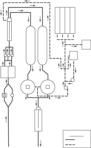
A typical oxidation ditch plant layout is illustrated in Figure 23-17 . Note that while prelimi-
nary treatment is provided, primary treat
ment is not. This is typical.
Redundancy. Two units are provided for redundancy. They may be constructed with work
space between them or with a common wall.
Preliminary Treatment. Bar screens or mechanical screens should be used instead of grinders
or shredders. The shredd
ed material has a tendency to mat and either float or collect on the aera-
tor brushes.
Primary Treatment. Typically, primary treatment is not provided. This implies an additional
solids load on the secondary clarifier beyond the production of biological solids.
Process Alternatives. Oxidation ditches have been operated in the following proc
ess configurations:
• Carbonaceous BOD removal,
• Carbonaceous BOD removal and nitrification,
• Carbonaceous BOD removal, nitrification, denitrification, and biological phosphorus
removal.
SECONDARY TREATMENT BY SUSPENDED GROWTH BIOLOGICAL PROCESSES 23-49
T ypically, the process selected is extended aeration to nitrify and remove carbonaceous BOD.
One of the primary reasons for selecting extended aeration is that it minimizes sludge production
by providing a long period for endogenous decay of the sludge mass.
Design Loading.
Unlike grit removal, primary settling, and secondary settling, suspended
growth biological treatment systems are not hydraulically limited. They are process limited.
Therefore, the loading (flow rate concentration) is an important design parameter.
Based on an extended aeration process alternative with equalization, the typi
cal design flow
rate is the annual average daily flow rate. Otherwise, the plant must hydraulically process daily
peaks. It is recommended that the average BOD/NH
4
–N loads (in kg/d) for the peak month be
used as a basis for design (Young et al., 1978).
Type of Reactor. The flow regime of the oxidation ditch is classified as plug flow. However,
the flow in the channel dilutes the incoming wastewater by a factor of 20 to 30. As a result, the
process kinetics approach that of a completely mixed reactor.
Modeling Equations. Be
cause the process kinetics approach that of a completely mixed reac-
tor, Equations 23-11 through 23 -19 are applicable. For municipal system s, WEF (1998) recom-
mends that process design using the kinetic approach be based on an effluent soluble substrate
concentration of zero, that is, S
0. When both carbonaceous oxidation and nitrification are
treatment objectives, nitrification growth kinetics (Equations 22-28 and 22-29) are assumed to
govern (Mandt and Bell, 1982; U.S. EPA, 1975a).
Disinfection
Bypass screen
Influent
Effluent
to
river
Clarifier
Sludge
pumps
Sludge
storage
tank
Scum pit
Sludge
drying
beds
Return sludge
Grit
chamber
Clarifier
Raw
sewage
pumps
Wet
wells
Mechanical screen
Liquid
Sludge
Legend
Oxidation ditch
Oxidation ditch
FIGURE 23-17
T ypical oxidation ditch plant layout.
( Source: U.S. EPA, 1977.)

23-50 WATER AND WASTEWATER ENGINEERING
Kinetic coefficients for removal of bCOD by heterotrophic bacteria are given in Table 23-13 .
The kinetic coefficients for design of nitrification with activated sludge are given in Table 23-14 .
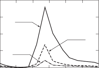
Safety Factor. Based on analysis of data at Chapel Hill, U.S. EPA (1975a) developed
Figure 23-18 . From this graph it appears that an SRT safety factor of 2.5 is reas onable. Unlike
the Rittmann and McCarty (2001) safety factor in Table 23-5 , this safety factor is to accou nt for
the ratio of peak to average ammonia concentrations.
Mixed Liquor Suspended Solids (MLSS). The MLSS is typically in the range of 3,000 to
5,000 mg/L (GLUMRB, 2004; Metcalf & Eddy, 2003). Mixed liquor volatile suspended solids
(MLVSS) is often assumed to be 70 to 80 percent of MLSS for plants treating primarily dome
stic
wastewater.
Coefficient Range Typical value
m
, g VSS/g VSS · d
3.0–13.2 6.0
K
s
, g bCOD/m
3
5.0–40.0 20.0
Y, g VSS/g bCOD
0.30–0.50 0.40
k
d
, g VSS/g VSS · d
0.06–0.20 0.12
f
d
a
, g/g
0.08–0.2 0.15
Values for in the temperature correction equation: C
t
C
20
()
T 20
m
1.03–1.08 1.07
K
s
1.00 1.00
k
d
1.03–1.08 1.04
TABLE 23-13
Activated sludge kinetic coefficients for heterotrophic bacteria at 20 ⴗ C
a
f
d
fraction of cell mass remaining as cell debris.
A dapted from Metcalf & Eddy, 2003.
Coefficient Range
Typical value
b
mn
, g VSS/g VSS · d
0.20–0.90 0.75
K
n
, g NH
4
-N/m
3
0.50–1.0 0.74
Y
n
, g VSS/g NH
4
-N
0.10–0.15 0.12
k
dn
, g VSS/g VSS · d
0.05–0.15 0.08
K
0
, g/m
3
0.40–0.60 0.50
Values for in the temperature correction equation: C
T
C
20
()
T 20
n
1.06–1.123 1.07
K
n
1.03–1.123 1.053
k
dn
1.03–1.08 1.04
TABLE 23-14
Activated sludge nitrification kinetic coefficients at 20 ⴗ C
a
a
Because reported nitrification kinetics cover a wide range, bench-scale or in plant
testing are recommended.
b
Updated values may be found in Choybert, et al., 2009.
A dapted from Metcalf & Eddy, 2003.
SECONDARY TREATMENT BY SUSPENDED GROWTH BIOLOGICAL PROCESSES 23-51
Solids Retention Time (SRT). To achieve endogenous decay, the solids retention time (mean
cell residence time,
c
) is typically on the order of 15 to 30 days (Metcalf & Eddy, 2003). Longer
times (up to 40 days) may be used to reduce sludge wasting.
Dissolved Oxygen. For nitrification to proceed uninhibited, the DO must be above 2.0 mg/L.
As noted in Chapter 22, nitrification rates increase with increasing DO up to about 3 or 4 m
g/L.
Because surface aerators at fixed locations are typically used, the DO level drops with dis-
tance from the aerators. Thus, in addition to providing adequate ox ygen, there must be enough
aerators placed at reasonable distances between units. The provision of adequate velocity and
aerator spacing i
s discussed later in this section.
Hydraulic Detention Time. The hydraulic detention time is not a basis for design. Although it
appears in tables of design parameters, it is likewise not a design criterion. It does serve as a check
on the results of model calculations and is ess
ential in estimating the volume of the reactor. Typi-
cal hydraulic detention times for CLRs are in the range 15 to 30 hours (Metcalf & Eddy, 2003).
Return Activated Sludge (RAS). Because of the need to retain nitrifying organisms in suf-
ficient concentration, the upper bound for the range of RAS for CLRs is higher than that for con-
ventional or completely mixed activated slu
dge processes for carbonaceous BOD oxidation. The
range is from 75 to 150 percent of the influent flowrate (Metcalf & Eddy, 2003).
Wasting. Although the design premise of the extended aeration process is “zero net cell
production,” wasting of solids will be required to prevent an accumulation of solids in the oxida-
tion ditch. Beca
use there is no primary treatment, there will be inert material from the raw waste-
water as well as cell debris that is not readily biodegradable that will accumulate.
Ditch Shape. The general shape of the CLR is typically an elongated oval. Other configura-
tions include bent at one end, bent at both ends, folded in half, serpentine, and circular. The
channels may be separated by a
dividing wall or by a center island.
Shallow channels are typically 1.2 to 1.8 m deep with 45 degree sloping side walls. Deep
channels have vertical side walls and are normally 3 to 4.2 m deep (U.S. EPA, 1978). The ditch is
typically constructed of concrete, but lined earth structures
have also been used.
2400
0
5
10
15
20
0400 0800 1200 1600 2000 2400
N
1
1.5
SF 1.5
N
1
5.5
SF 2.0
SF 2.5
N
1
0.6
Time,hr
Effluent NH
4
N concentrtion, mg/L
N
1
24 hr average
composite NH
4
N
concentration
+
+
FIGURE 23-18
Effect of safety factor (SF) on diurnal variation in effluent
a mmonia.
( Source: U.S. EPA, 1975a.)

23-52 WATER AND WASTEWATER ENGINEERING
Ditch Velocity. Typically, the design velocity in the channel is 0.3 m/s. The movement through
the channel is provided by the surface aerators. Brush or disk aerators are commonly used. Manu-
facturers rate the aerators on a volume per meter of rotor length basis to maintain a velocity of
approximately 0.3
m/s ( Table 23-15 ). Rotor length, speed, immers ion, d itch dimensions, and
baffles all influence the velocity, so there is no exact design to achieve the desired velocity.
Dimensions. The volume is determined by the flow rate and hydraulic detention time
( Equation 23-11 ). The hyd
raulic detention time is based on the kinetic equation ( Equation 23-15 ).
Manufacturers provide rules-of-thumb for liquid depth and channel width relationships that
are a function of the rotor length. An example of these rules-of-thumb is given in Table 23-16 .
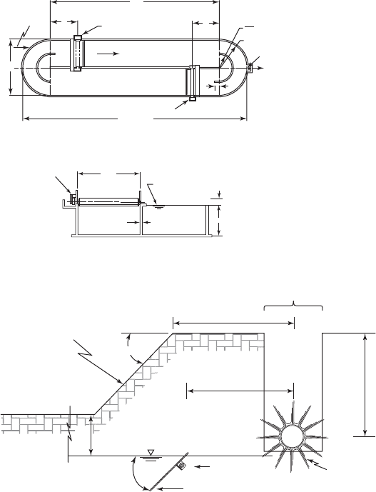
Baffles. To minimize solids deposition and
maintain flow streamlines, return flow baffles are
required in ditches with a center dividing wall ( Figure 23-19 ). The following list provides an
example of the rules for design of the baffles:
• Radius channel width/2.
• Offset into incoming flow W/15.
TABLE 23-15
Typical manufacturer’s brush surface aerator rotor data
a
Model
Diameter,
mm
Length
available,
m
Speed
range,
rpm
Rotor capacity,
m
3
/m
SOTR,
kg/kWh
kg O
2
per h
per m
M 610 0.9–3.7 60–90 200 1.8 2.7
S915 1.8–4.9 55–85 230 2.0 6.1
U 1,066 1.8–9.2 50–72 260 2.2 8.2
D ual rotors may be employed to double the available length.
a
For academic use. Use actual manufacturer’s data for design.
TABLE 23-16
Rules-of-thumb for liquid depth and channel width for oxidation ditch
a
Liquid depth (D) Rotor length (RL) Channel width (W)
Comment
2 m 1 to 5 m
W/RL 3.0 to 1.8
Higher ratio with shorter
rotor lengths
2 5 m
W RL 3 m
2 m
W RL
Maximum depth for rotor models M & S 2 m See Table 23-15
Maximum depth for rotor model U 5
m See Table 23-15
With center island: W (1.5) (width of island)
Freeboard 0.3 m for rotor models M & S
Freeboard 0.5 m for rotor model U
a
For academic use. Use actual manufacturer’s data for design.
SECONDARY TREATMENT BY SUSPENDED GROWTH BIOLOGICAL PROCESSES 23-53
• Baffle extends 450 mm above liquid level.
• For channel width 14 m, two baffles are required.
In addition to baffles in the return flow, baffles are required downstream of the rotor if the
liquid depth exceeds 2 m. An example of this baffle is shown in Figure 23-20 .
Aerators. The suggested design condition for sizing the ox ygen supply system is the peak
BOD and ammonia load to be removed plus 50 percent of the peak four-hour load above the peak
day rate (Young et al., 1978). This is very conservative. Current practice is to use the peak day.
Although vertically mounted aerators have been used, the horizontally mounted brush and
d
isc aerators are more common. The oxygen transfer efficiency varies with the transfer rate. The
factors that influence performance are the rotational speed and immersion. In the case of the disk
aerators, the number of discs per meter of length also influences the performance.
Influent
6m
6m
Brush rotor
Flow
Brush rotor
2 W
L2W
Effluent
Outlet wei
r
L
W/15
W
2
R
W R
W
300 mm
Wall
Water level
Rotor
0.6 m
3.0 to 4.2 m
Reactor cross section
FIGURE 23-19
Baffle placement and dimensions.
1.8 m
1.5 m
1.6 m
Brush
aerator
Flow
Rotor channel
45°
Splash wall
Free board
Baffle
Adjustable angle 15° to 60°
0.6 m
FIGURE 23-20
Downstream baffle for liquid depth greater than 2 m.
23-54 WATER AND WASTEWATER ENGINEERING
In addition to the normal consideration of oxygen transfer rate and efficiency, the flexibility
in operation should also be a factor in aerator selection. Some options to consider are variable
speed and adjustable immersion depth.
Aerator Placement. Influ ent and return activated sludge (RAS) fed to the channel should be
located jus
t upstream of a rotor assembly to afford immediate mixing with the tank mixed liquor.
Effluent from the channel should be far enough upstream of a rotor and far enough upstream of
the raw wastewater influent and RAS to prevent short circuiting.
The velocity in the channel controls the location of the aerators. The U.S. EPA (1977)
recommends that velocit
y be such that the travel time between aerators be no more than three to
four minutes. Typically, rotors are placed in pairs. From the rec ommended velocity of 0.3 m/s
and a maximum travel time of four minutes the maximum distance between rotors is
Distanc
e m/s min s/min m()()( )0 3 460 72.
For two rotors, this implies a maximum ditch length of 2 72 m = 144 m; for four rotors, the
impled maximum ditch length is 4 72 m = 288 m.
Alkalinity. As noted in Chapter 22 (Equation 22-25) alkalinity is required to buffer the nitrifi-
c
ation reaction. The required alkalinity may be estimated by the following equation (Metcalf &
Eddy, 2003):
Alkalinity to maintain pH Influent Alk Al 7 kkused Alktobeadded
(23-60)
Typically the amount of residual alkalinity to maintain the pH near neutral is between 80 and
90 mg/L as CaCO
3
.
Options for adding alkalinity:
• Sodium bicarbonate (NaHCO
3
) is most often recommended because it is easy to handle and
it causes few scaling problems.
• Soda ash (sodium carbonate, Na
2
CO
3
) is also easy to handle and is generally less expensive
than NaHCO
3
.
• Lime (CaO) is the least expensive but has several drawbacks. It has a propensity to form
scale, it cakes and, thus, is more difficult to feed, and it produces more sludge.
Secondary Settling. The design of the secondary settling tank for this system is discuss
ed in
Chapter 25.
Appurtenances. Two important appurtenances are a weir to control the liquid level in the
channel and rotor covers. The weir should be adjustable. Rotor covers may be required in cold
climates to prevent icing.
Design Examples. The following five example problems illustrate the estimation of the volume
of the oxidation ditch, required alkalinity addition,
sludge production, number of brush aerators
required, and the dimensions of the ditch and placement of the rotors.

SECONDARY TREATMENT BY SUSPENDED GROWTH BIOLOGICAL PROCESSES 23-55
Example 23-8. Estimate the volume of an extended-aeration oxidation ditch for carbonaceous
BOD oxidation and nitrification for the city of Cartouche Lake using the following design data:
Influent data
D e sign flow rate 14,200 m
3
/ d
bCOD 205 mg/L
NH
3
-N 16.8 mg/L
Total suspended solids (TSS) 160 mg/L
Biodegradable volatile suspended solids = 95 mg/L
Minimum sustained temperature 12 C
pH 7.0
Alkalinity 90 mg/L as CaCO
3
Effluent discharge standards
bCOD 20 mg/L
NH
3
-N 1.0
TSS 10 mg/L
A ssume MLSS 3,000 mg/L, MLVSS (0.7) MLSS, and DO 3.0 mg/L.
Solution:
a. Assume nitrification governs, and select the following kinetic coefficients from
Table 23-14 :
Coefficient for temperature correction
mn
, g VSS/g VSS · d
0.75 1.07
K
n
, g NH
4
-N/m
3
0.74 1.053
Y
n
, g VSS/g NH
4
-N
0.12
k
dn
, g VSS/g VSS · d
0.08 1.04
K
0
, g/m
3
0.50
b. Correct kinetic coefficients to 12
C because this temperature limits the growth rate of
nitrifying organisms. Use the correction equations in Table 23-14 .
nmax
g VSS/g VSS d
()()075 107 04
12 20
...44
074 105
4
3
g VSS/g VSS d
gNH N/m
K
n
()(.-.33 049
008
12 20
4
3
)
(
.-
.
gNH N/m
gVSS/gVk
dn
SSS d g VSS/g VSS d
)( )104 006
12 20
..
c. Estimate
n
using Equation 22-28. The value selected for N i s the design effluent c on-
centration because that is limiting. The DO is the design DO that must be achieved by
the design of the aeration system.
n
()044
10
049
3
4
.
.
.
g VSS/g VSS
g/m
gNH-N/m
333
3
33
10
3 0
0 50 3 0.
.
..g/m
g/m
g/m g/m
⎛
⎝
⎜
⎞
⎠
⎟
⎛⎛
⎝
⎜
⎞
⎠
⎟
⎡
⎣
⎢
⎢
⎤
⎦
⎥
⎥
006
04
.
.
g VSS/g VSS d
n
[( 440670857006019)( )( )].. . .
d
1
23-56 WATER AND WASTEWATER ENGINEERING
d. Using Equation 23-17 calculate
c min
1
019
5 26
1
c
n
c
min
min
d
d
.
.
e. Using a safety factor of 2.5 from Figure 23-18 ,
c
2 5526 13 15.. .()dd
f. Estimate U for BOD oxidation using Equation 23-19 and the kinetic coefficients from
Table 23-13 corrected for temperature . Solve Equation 23-19 for U.
Uk
Y
U
c
d
11
1
13 15
0
1
⎛
⎝
⎜
⎜
⎞
⎠
⎟
⎟
⎛
⎝
⎛
⎝
⎞
⎠
.
.09
d
d
⎜⎜
⎞
⎠
⎟
⎛
⎝
⎞
⎠
1
040
0415
1
.
.
d
g. Solve Equation 23-18 for . Call this
BOD
. Use this to estimate
BOD
for the assumed
MLSS 3,000 mg/L and a conservative assumption of S 0 as recommended by WEF
(1998):
BOD
g/m g/m
d g/m
205 0
0415 2 100
33
1 3
()(
)
.,
0235. d or 5.64 h
h. As in step (f), estimate U for nitrification using Equation 23-19 and the kinetic coeffi-
cients from Table 23-14 corrected for temperature.
U
1
13 15
006
1
012
0136833 1
.
.
.
.. .
⎛
⎝
⎞
⎠
⎛
⎝
⎞
⎠
()()113
1
d
i. An estimate of the fraction of MLVSS that is nitrifying organisms is required to calcu-
late for nitrification. Using Equation 22-29:
f
N
()( )
()(
016 168 1
06 205 0
33
3
..
.
g/m g/m
g/m
))( )( )
016 168 1
2 53
123 2 53
0
33
..
.
.
.
g/m g/m
002
Note that the NH
3
concentrations were given in the problem statement. The MLVSS of
nitrifying organisms is
MLVSS mg/L mg/L()( )0 02 2 100 42.,
SECONDARY TREATMENT BY SUSPENDED GROWTH BIOLOGICAL PROCESSES 23-57
j. As in step (g), estimate
nitrification
.
nitrification
g/m g/m
d
16 8 1 0
113
33
1
..
.()
(()42
0 33 799
3
g/m
d or h ..
The hydraulic detention time for nitrification governs.
k. The volume of the oxidation ditch is estimated to be
Q ()() ( )( ) 14 200 0 33 4 686 4 7
3
,.,,m /dd or 000
3
m
V
l. To provide redundancy and flexibility of operation, two or three ditches should be
provided. Assuming two ditches, the volume of each ditch is estimated to be 12,700 m
3
.
Comment. Alkalinity is required to buffer the nitrification reaction. The estimation of the alka-
linity required and the chemical dose to adjust it are explained in the next example.
Example 23-9. Determine whether or not there is sufficient alkalinity for nitrification of the
extended aeration oxidation ditch at Cartouche Lake ( Example 23-8 ). Compute the ma
ss per day
of sodium bicarbonate to add if alkalinity is required. Assume a residual of 80 mg/L as CaCO
3
i s
required to maintain the pH.
Solution:
a . Compute the residual alkalinity using Equation 23-60 .
Influent alkalinity from influent (Example 23-8) 90 mg/L as CaCO
3
.
From Example 23-8 the amount of nitrogen converted to nitrate 16.8 mg/L1.0 mg/L
15.8 mg/L 15.8 g/m
3
.
From Equation 22-25, the alkalinity used in nitrification (7.14 g CaCO
3
/g NH
4
-N)
(15.8 g/m
3
) 112.8 g/m
3
.
U sing the assumption that 80 mg/L as CaCO
3
i s required to maintain the pH, the alkalin-
ity balance is
80 90 112 8
33 3
g/m g/m g/m alkalinity to ad . dd
Solving for alkalinity to add:
alkalinity to add g/m g/m g/m 80 112 8 90
33
.
333
3
102 8 .g/m as CaCO
The mass per day is
()()(102 8 14 200 10
3
3
33
.,g/m as CaCO m /d kg/
gg kg/d) 14598,.