Tsoulfanidis N. Measurement and detection of radiation
Подождите немного. Документ загружается.

398
MEASUREMENT
AND DETECTION OF RADIATION
12.5
DETECTION OF GAMMAS
WITH
AN NE
213
ORGANIC SCINTILLATOR
The NE 213 organic scintillator has emerged as one of the leading fast neutron
spectrometers (see Chap. 14). As a gamma spectrometer, the NE 213 scintillator
has an efficiency lower than that of
NaI(T1) and an energy resolution that is
poor compared to that of semiconductor detectors. There are certain applica-
tions, however, where high-energy resolution is not the most important factor.
One such application is detection of gammas in a mixed neutron-gamma field.
There, the ability of the NE 213 scintillator to discriminate against neutrons
makes it an attractive gamma detector.
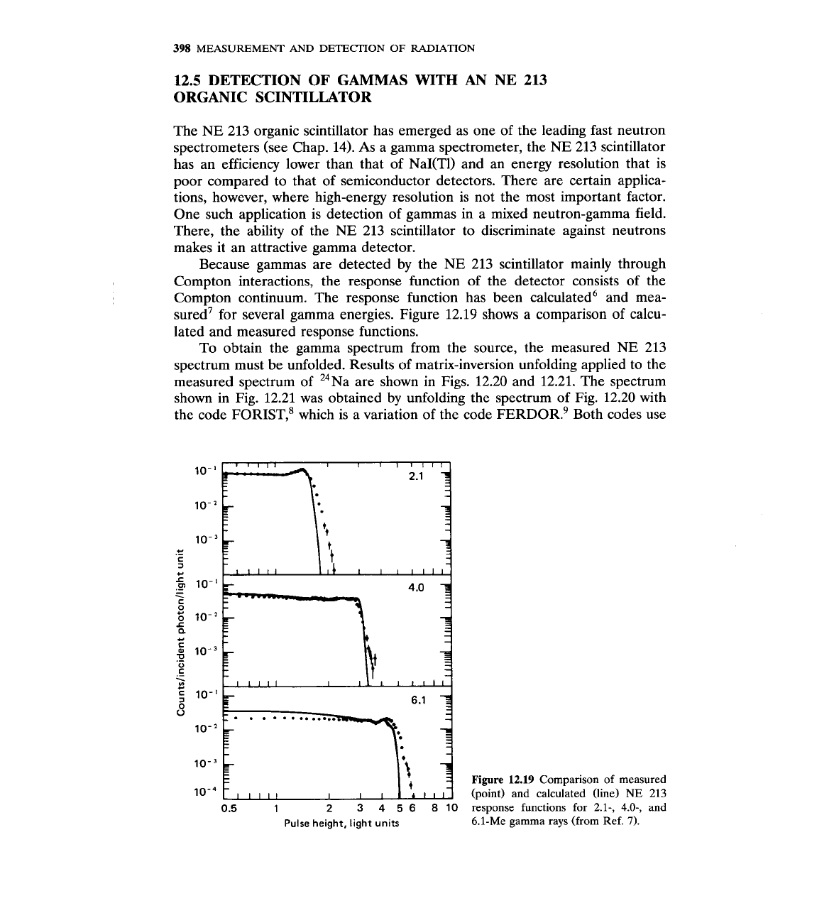
Because gammas are detected by the NE 213 scintillator mainly through
Compton interactions, the response function of the detector consists of the
Compton continuum. The response function has been calculated6 and mea-
sured' for several gamma energies. Figure 12.19 shows a comparison of calcu-
lated and measured response functions.
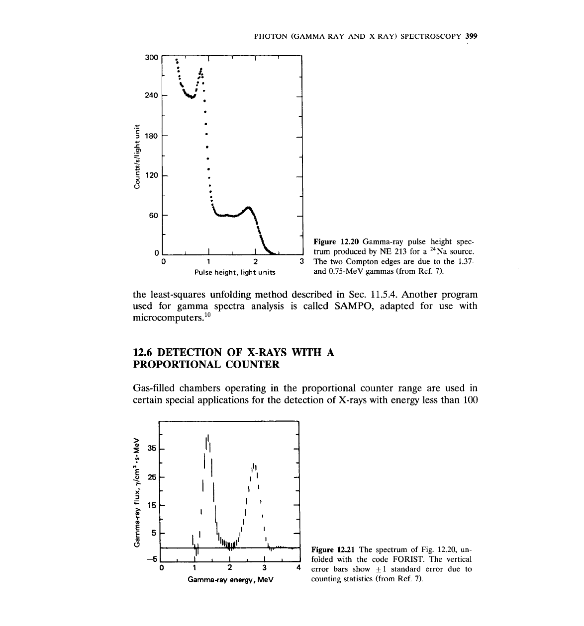
To obtain the gamma spectrum from the source, the measured NE 213
spectrum must be unfolded. Results of matrix-inversion unfolding applied to the
measured spectrum of 24~a are shown in Figs. 12.20 and 12.21. The spectrum
shown in Fig. 12.21 was obtained by unfolding the spectrum of Fig. 12.20 with
the code
FORIST,~ which is a variation of the code FERDOR.~ Both codes use
Figure
12.19
Comparison of measured
(point) and calculated (line)
NE
213
response functions for 2.1-,
4.0-,
and
Pulse height, light units
6.11~e gamma rays (from Ref.
7).
PHOTON
(GAMMA-RAY
AND
X-RAY)
SPECTROSCOPY
399
Figure
12.20
Gamma-ray pulse height spec-
trum produced by
NE
213 for
a
24~a source.
0
1
2
3
The two Compton edges are due to the 1.37-
Pulse
height,
light
units
and 0.75-MeV gammas (from Ref. 7).
the least-squares unfolding method described in Sec. 11.5.4. Another program
used for gamma spectra analysis is called
SAMPO,
adapted for use with
microcomputers.10
12.6
DETECTION OF
X-RAYS
WITH
A
PROPORTIONAL COUNTER
Gas-filled chambers operating in the proportional counter range are used in
certain special applications for the detection of X-rays with energy less than 100
Figure 12.21
The spectrum of Fig. 12.20, un-
folded with the code FORIST. The vertical
error bars show
f
1 standard error due to
Gamma-ray
energy,
MeV
counting statistics (from Ref. 7).
400
MEASUREMENT
AND
DETECTION
OF
RADIATION
keV. At this energy range, the photons interact only through the photoelectric
effect. Since the photoelectric cross section increases as
Zm,
with
rn
-
3-5, it is
important to have a window made of very low-Z material and a gas with as high
a Z value as possible.
X-ray proportional counters are usually cylindrical with a very thin beryl-
lium window located either on the side or at the front end. They use a gas that is
a mixture of a noble gas-He, Ne,
Ar,
Kr,
Xe-with methane, at a pressure of
about
1
atm.
The energy resolution of these counters is such that the
FWHM
is 1-2 keV
at 20 keV. Thus, proportional counters are superior to scintillation counters in
this energy range.
12.7
DETECTION OF GAMMAS
WITH
Ge DETECTORS
As mentioned in Sec. 7.5.5, the Ge(Li) detectors have been replaced by Ge
detectors, which are devices that use hyper pure germanium (impurity concen-
tration
1016
atoms/m3 or less). The main advantage of
Ge
over Ge(Li) detectors
is that the former should be kept at low temperatures only when in use; the
latter must be kept cool at all times.
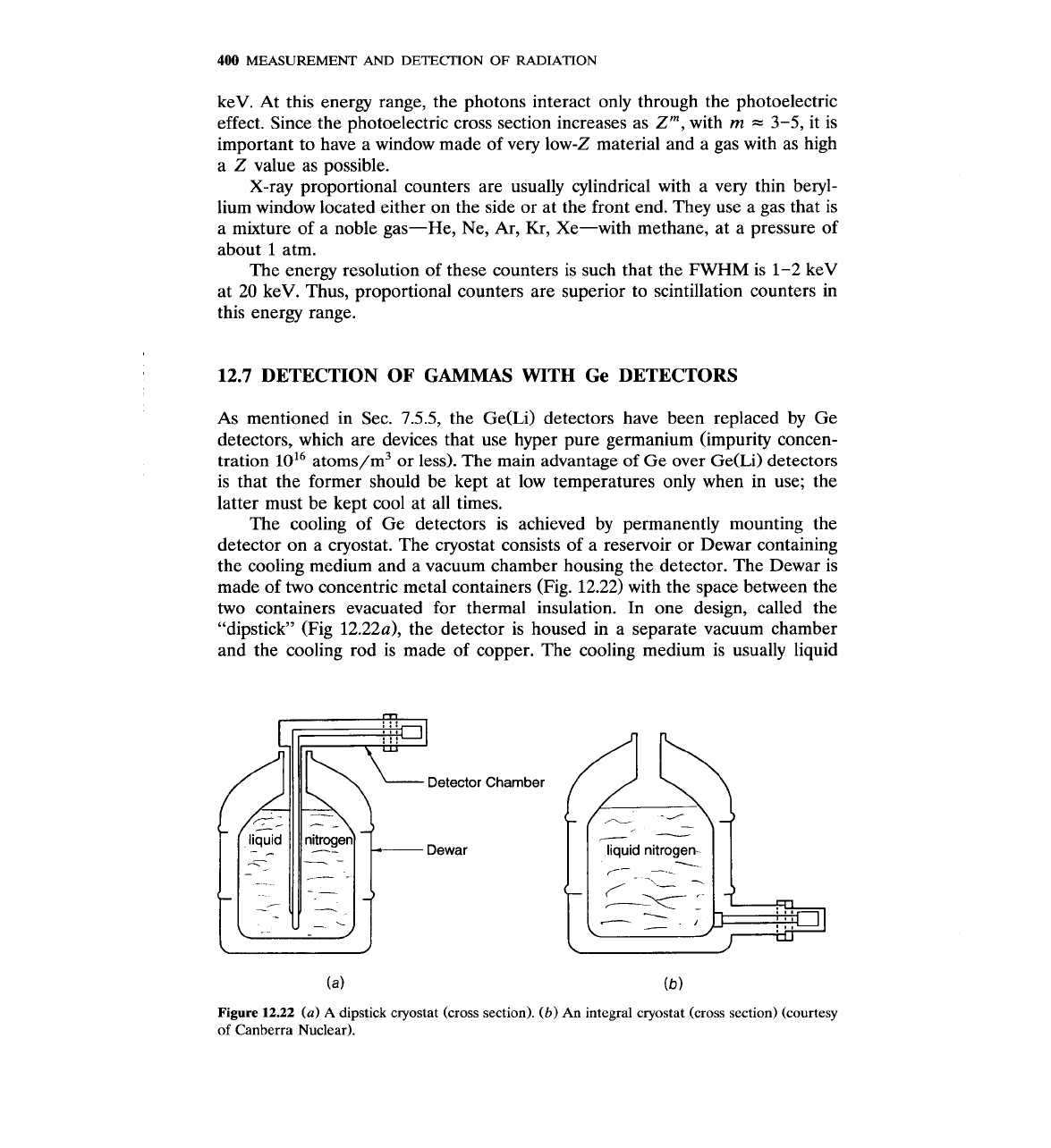
The cooling of Ge detectors is achieved by permanently mounting the
detector on a cryostat. The cryostat consists of a reservoir or Dewar containing
the cooling medium and a vacuum chamber housing the detector. The Dewar is
made of two concentric metal containers (Fig. 12.22) with the space between the
two containers evacuated for thermal insulation. In one design, called the
"dipstick" (Fig 12.22a), the detector is housed in a separate vacuum chamber
and the cooling rod is made of copper. The cooling medium is usually liquid
Detector
Dewar
Chamber
liquid nitrogen
r--.
_---
C---
Z
Figure
12.22
(a)
A
dipstick cryostat (cross section).
(b)
An
integral cryostat (cross section) (courtesy
of Canberra Nuclear).
nitrogen (boiling temperature
-
196"C, or
77
K).
In another design, called the
integral cryostat (Fig. 12.226), there is a common vacuum chamber for both the
Dewar and the detector. One version of the integral cryostat is provided with a
rotary vacuum seal, which allows the detector chamber to be rotated
180".
With
respect to cooling, one manufacturer (Canberra) has designed and is offering a
cryoelectric cryostat that uses a commercial refrigerator with helium gas as the
refrigerant.
The vacuum chamber that contains the detector is made of stainless steel.
The chamber protects the detector from dirt and, by being evacuated, prevents
condensation of vapor on the detector surface or electrical discharge when high
voltage is applied to the detector.
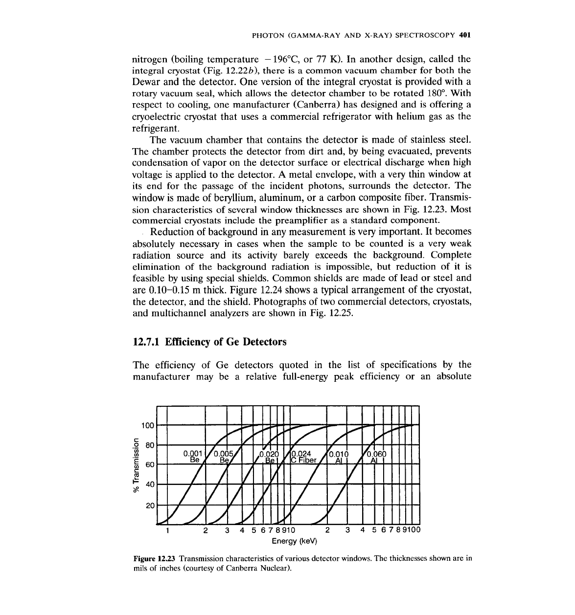
A
metal envelope, with a very thin window at
its end for the passage of the incident photons, surrounds the detector. The
window is made of beryllium, aluminum, or a carbon composite fiber. Transmis-
sion characteristics of several window thicknesses are shown in Fig. 12.23. Most
commercial cryostats include the preamplifier as a standard component.
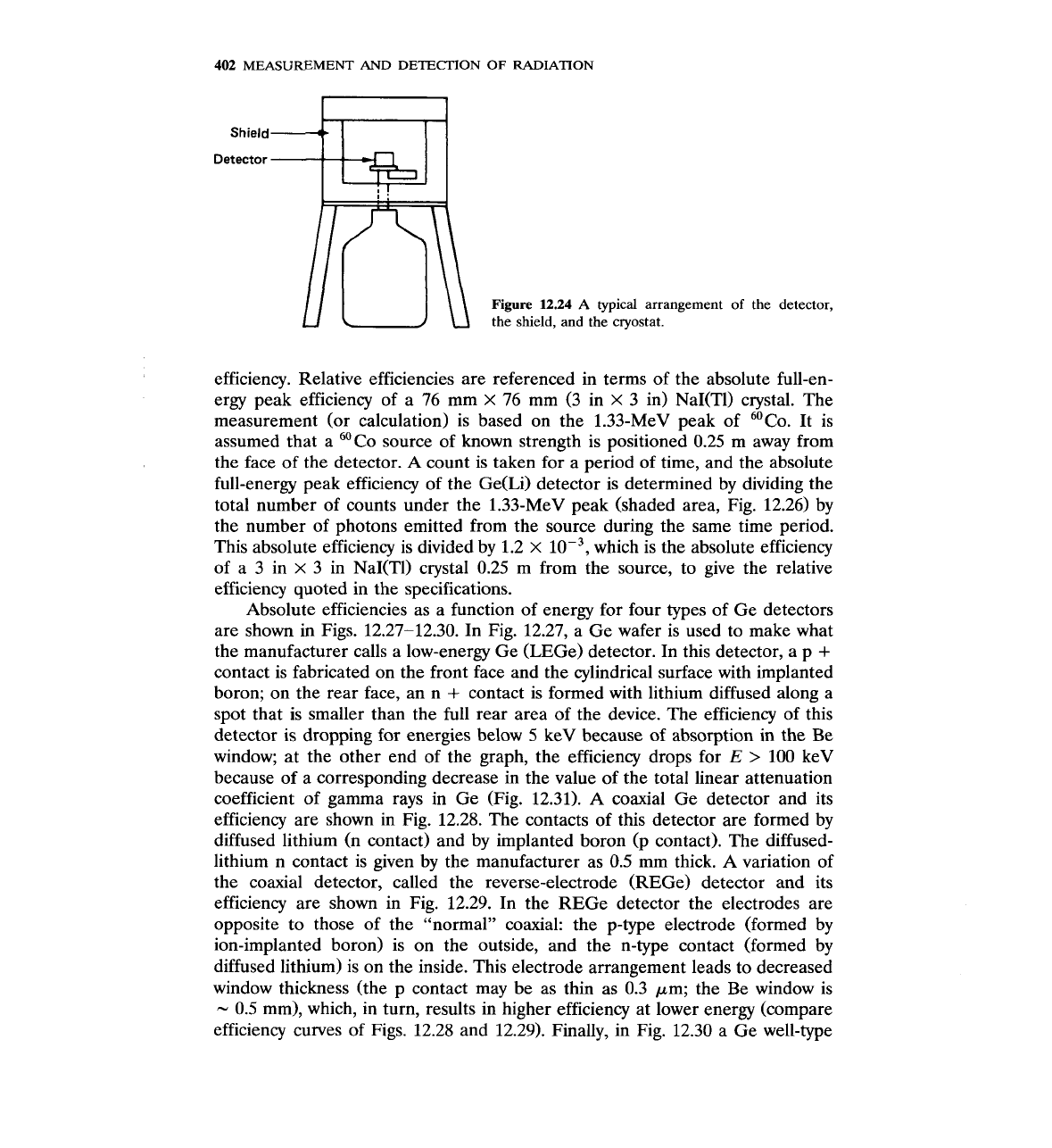
Reduction of background in any measurement is very important. It becomes
absolutely necessary in cases when the sample to be counted is a very weak
radiation source and its activity barely exceeds the background. Complete
elimination of the background radiation is impossible, but reduction of it is
feasible by using special shields. Common shields are made of lead or steel and
are
0.10-0.15
m thick. Figure
12.24
shows a typical arrangement of the cryostat,
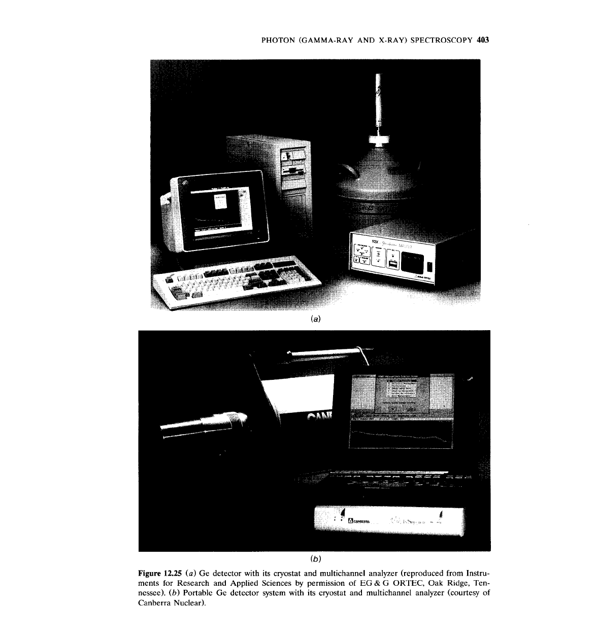
the detector, and the shield. Photographs of two commercial detectors, cryostats,
and multichannel analyzers are shown in Fig.
12.25.
12.7.1
Efficiency
of
Ge Detectors
The efficiency of Ge detectors quoted in the list of specifications by the
manufacturer may be a relative full-energy peak efficiency or an absolute
Energy (keV)
Figure
12.23
Transmission characteristics of various detector windows. The thicknesses shown are in
mils of inches (courtesy of Canberra Nuclear).
402
MEASUREMENT
AND
DETECTION
OF
RADIATION
Shield
t.
Detector
--*
L
u
1
Figure
12.24
A
typical arrangement of the detector,
the shield, and the cryostat.
efficiency. Relative efficiencies are referenced in terms of the absolute full-en-
ergy peak efficiency of a 76 mm
X
76 mm (3 in
X
3 in) NaI(T1) crystal. The
measurement (or calculation) is based on the 1.33-MeV peak of 60~o. It is
assumed that a
60Co source of known strength is positioned 0.25 m away from
the face of the detector. A count is taken for a period of time, and the absolute
full-energy peak efficiency of the Ge(Li) detector is determined by dividing the
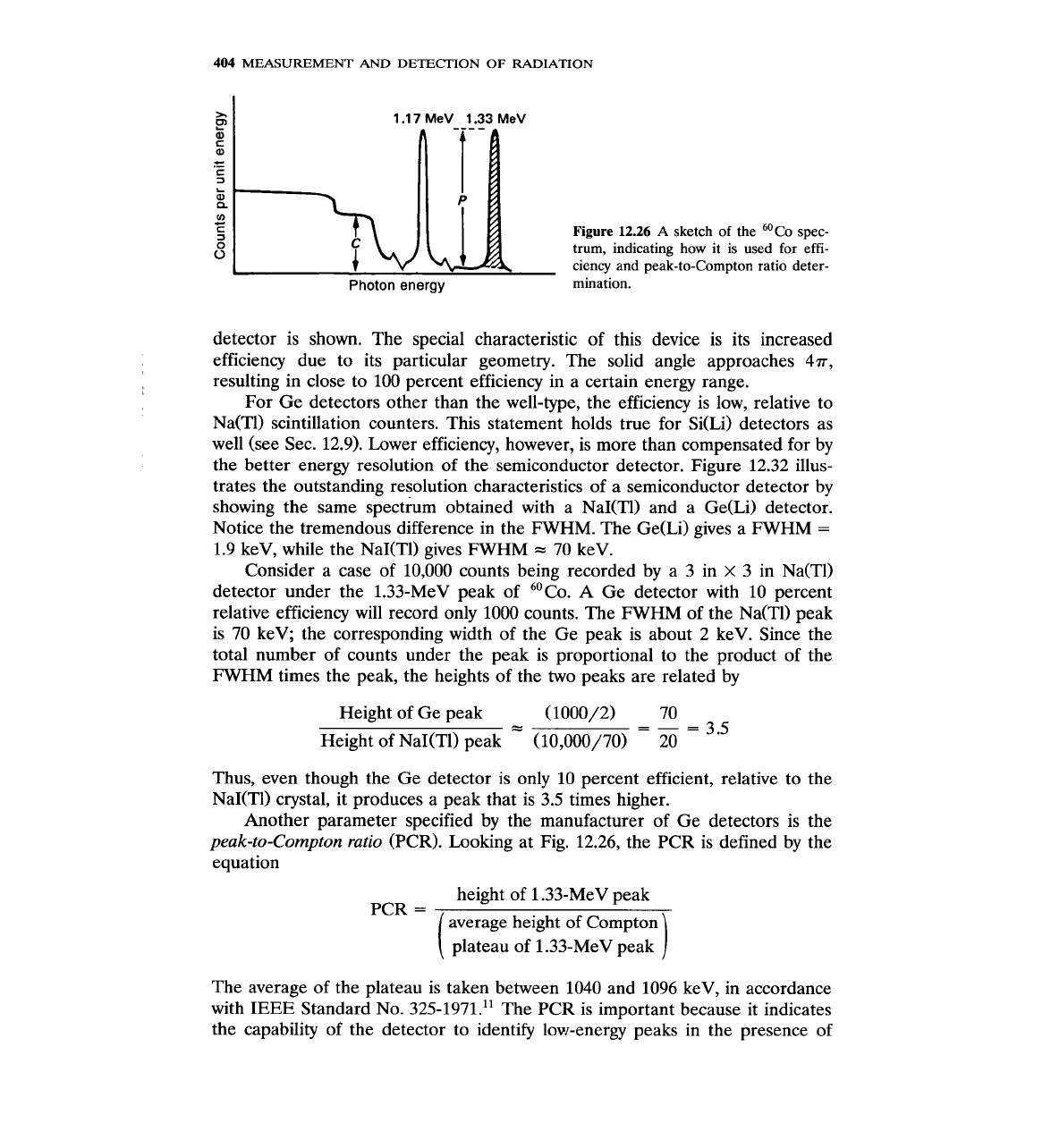
total number of counts under the 1.33-MeV peak (shaded area, Fig. 12.26) by
the number of photons emitted from the source during the same time period.
This absolute efficiency is divided by 1.2
x
lop3, which is the absolute efficiency
of a 3 in
x
3 in NaI(T1) crystal 0.25 m from the source, to give the relative
efficiency quoted in the specifications.
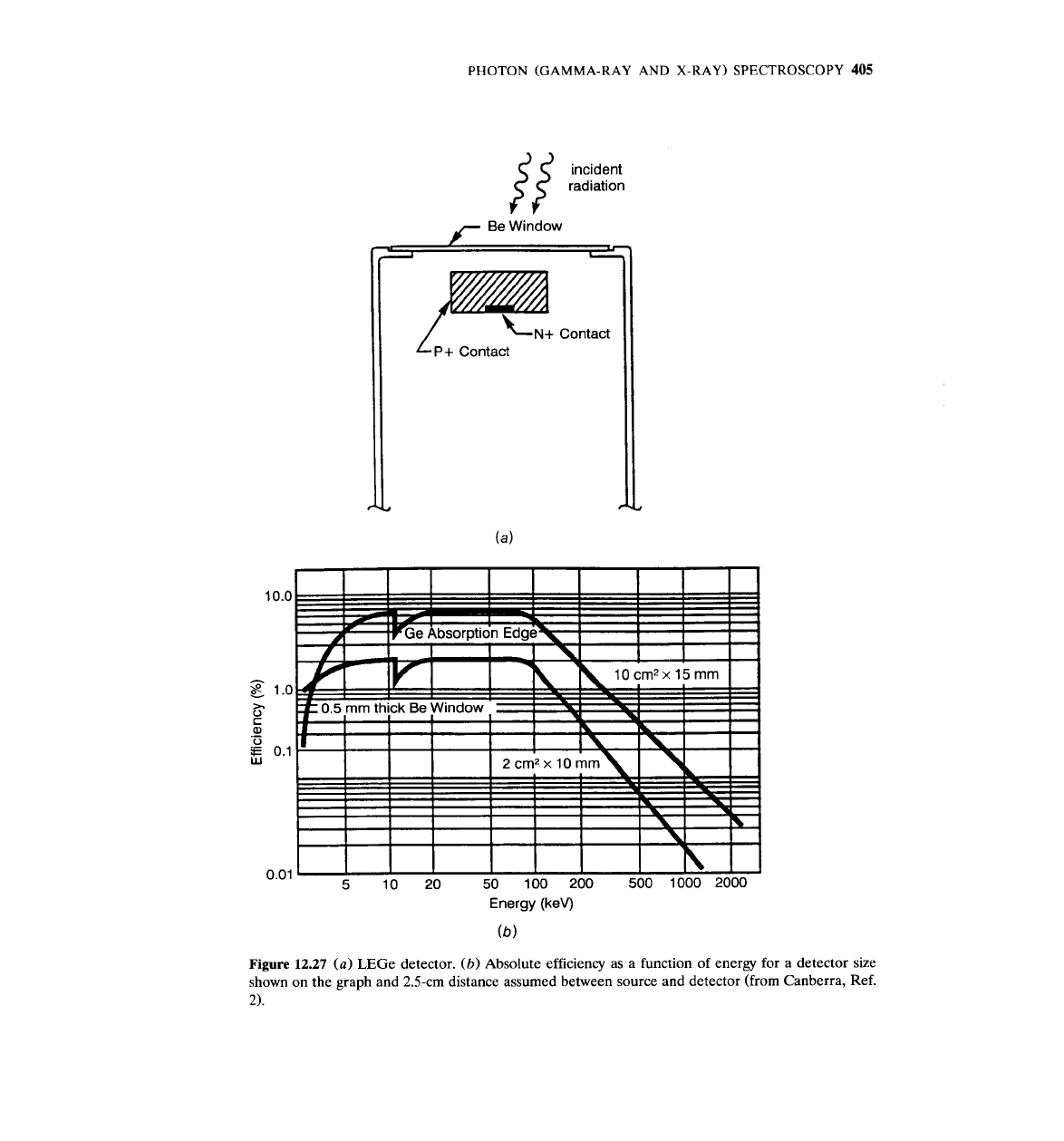
Absolute efficiencies as a function of energy for four types of Ge detectors
are shown in Figs. 12.27-12.30. In Fig. 12.27, a Ge wafer is used to make what
the manufacturer calls a low-energy Ge
(LEGe) detector. In this detector, a p
+
contact is fabricated on the front face and the cylindrical surface with implanted
boron; on the rear face, an n
+
contact is formed with lithium diffused along a
spot that is smaller than the full rear area of the device. The efficiency of this
detector is dropping for energies below 5 keV because of absorption in the Be
window; at the other end of the graph, the efficiency drops for
E
>
100 keV
because of a corresponding decrease in the value of the total linear attenuation
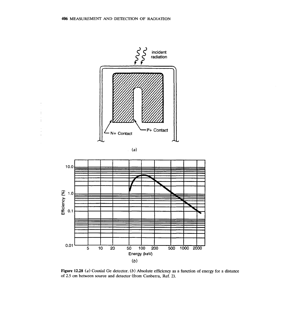
coefficient of gamma rays in Ge (Fig. 12.31). A coaxial Ge detector and its
efficiency are shown in Fig. 12.28. The contacts of this detector are formed by
diffused lithium
(n contact) and by implanted boron (p contact). The diffused-
lithium n contact is given by the manufacturer as 0.5 mm thick.
A
variation of
the coaxial detector, called the reverse-electrode (REGe) detector and its
efficiency are shown in Fig. 12.29. In the REGe detector the electrodes are
opposite to those of the "normal" coaxial: the p-type electrode (formed by
ion-implanted boron) is on the outside, and the n-type contact (formed by
diffused lithium) is on the inside. This electrode arrangement leads to decreased
window thickness (the p contact may be as thin as 0.3 pm; the Be window is
-
0.5 mm), which, in turn, results in higher efficiency at lower energy (compare
efficiency curves of Figs. 12.28 and 12.29). Finally, in Fig. 12.30 a Ge well-type
PHOTON (GAMMA-RAY AND X-RAY) SPECTROSCOPY
403
Figure
12.25
(a)
Ge detector with its cryostat and multichannel analyzer (reproduced from Instru-
ments for Research and Applied Sciences by permission of
EG
&
G
ORTEC, Oak Ridge, Ten-
nessee).
(b)
Portable Ge detector system with its cryostat and multichannel analyzer (courtesy of
Canberra Nuclear).
404
MEASUREMENT
AND
DETECTION
OF
RADIATION
I
1.1
7
MeV
1.33
MeV
Figure
12.26
A
sketch of the 60Co spec-
trum, indicating how it is used for effi-
ciency and peak-to-Compton ratio deter-
Photon energy
mination.
detector is shown. The special characteristic of this device is its increased
efficiency due to its particular geometry. The solid angle approaches 47r,
resulting in close to 100 percent efficiency in a certain energy range.
For Ge detectors other than the well-type, the efficiency is low, relative to
Na(Tl) scintillation counters. This statement holds true for Si(Li) detectors as
well (see Sec. 12.9). Lower efficiency, however, is more than compensated for by
the better energy resolution of the semiconductor detector. Figure 12.32 illus-
trates the outstanding resolution characteristics of a semiconductor detector by
showing the same spectrum obtained with a NaI(T1) and a Ge(Li) detector.
Notice the tremendous difference in the FWHM. The
Ge(Li) gives a FWHM
=
1.9 keV, while the NaI(T1) gives FWHM
=
70 keV.
Consider a case of 10,000 counts being recorded by a 3 in
X
3 in Na(T1)
detector under the 1.33-MeV peak of 60Co.
A
Ge detector with 10 percent
relative efficiency will record only 1000 counts. The FWHM of the Na(T1) peak
is 70 keV; the corresponding width of the Ge peak is about 2 keV. Since the
total number of counts under the peak is proportional to the product of the
FWHM times the peak, the heights of the two peaks are related by
Height of Ge peak
- -
(1000/2) 70
=
-
Height of NaI(Tl) peak (10,000/70) 20
=
3.5
Thus, even though the Ge detector is only 10 percent efficient, relative to the
NaI(Tl) crystal, it produces a peak that is 3.5 times higher.
Another parameter specified by the manufacturer of Ge detectors is the
peak-to-Compton ratio
(PCR). Looking at Fig. 12.26, the PCR is defined by the
equation
height of 1.33-MeV peak
PCR
=
average height of Compton
plateau of 1.33-MeV peak
The average of the plateau is taken between 1040 and 1096 keV, in accordance
with IEEE Standard No.
325-1971." The PCR is important because it indicates
the capability of the detector to identify lowenergy peaks in the presence of
PHOTON (GAMMA-RAY AND X-RAY) SPECTROSCOPY
405
10.1
g
I.'
).
0
C
a
.-
0
E
0.
W
0.0
incident
radiation
# #
1/-
Be Window
I
I
I
I
Absorption Edge\
1
I
I
I
I
I
I \I
1
I
I
Energy (keV)
(b)
Figure
12.27
(a)
LEGe detector.
(b)
Absolute efficiency as
a
function of energy for a detector size
shown on the graph and 2.5-cm distance assumed between source and detector (from Canberra, Ref.
2).
406
MEASUREMENT AND DETECTION
OF
RADIATION
Energy
(keV)
(b)
Figure 12.28
(a)
Coaxial Ge detector.
(b)
Absolute efficiency as a function of energy for a distance
of
2.5
cm between source and detector (from Canberra, Ref.
2).

PHOTON (GAMMA-RAY AND X-RAY) SPECTROSCOPY
407
incident radiation
Be Window
f
(0.5
mm)
N+
Contact
I
Energy (keV)
(b)
Figure 12.29
(a)
REGe coaxial detector. (b) Absolute efficiency as a function of energy for a
distance of
2.5
cm between source and detector (from Canberra, Ref.
2).