Tsch?tsch H., Koth A. Metal Forming Practise: Processes - Machines - Tools
Подождите немного. Документ загружается.

22.3 Constructional design 271
22.3.3 Counterblow hammers
Counterblow hammers have two rams which
strike one another. By this means the forces in
the frame are reduced as much as possible, so
these hammers need no bed or only a small
one.
The construction mass of a counterblow ham-
mer is only one-third of that of a hammer with
an anvil block which has the same work capac-
ity. From the point of view of the drive, the
counterblow hammer is a double-acting ham-
mer with a powered upper ram.
The lower ram is moved by a coupling with the
upper ram; this cou
p
ling is mechanical (steel
bands, Figure 22.6) or hydraulic (Figure 22.7)
Today, hammers with mechanical couplings
(Figure 22.6) are no longer built.
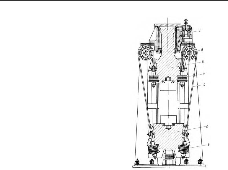
Figure 22.6 Counterblow hammer (Bêché & Grohs)
with steel band coupling, a) upper ram
with piston rod, b) lower ram, c) steel
bands, d) pulley, e) rubber buffer, f) pi-
lot valve
The counterblow hammer (Figure 22.7a, Bêché & Grohs system) is built with both pneumatic
and hydraulic drives. With this hammer, the upper and lower rams are connected by a hydrau-
lic coupling. It basically consists of two coupling pistons acting on the upper ram; on the
hammer stroke, these power the pistons acting on the lower ram via a column of oil (Figure
22.7a). The pistons are linked directly to the rams without any elastic connectors. The system
is low on maintenance due to its simple construction. The coupling cylinder below the lower
ram is fitted with a hydraulic brake. On the return stroke the lower ram is braked before reach-
ing the end of travel and is gently intercepted by the impact buffers, meaning that the bed only
has low forces (stresses) to absorb.
With the LASCO principle counterblow hammer (Figure 22.7b) both rams are driven towards
one another. The upper ram is accelerated as with a normal double-acting hammer. The lower
ram is driven by means of pre-stressed air buffers. As the rams have different masses (the
upper ram to lower ram mass ratio being around 1 : 5) the ram strokes and ram speeds are also
different. When the impact begins the upper ram piston is hydraulically actuated. At the same
time, the same valve is used to disengage the hydraulic cylinder via the upper ram and acceler-
ate the lower ram using the gas energy from the lower stressed air buffer. When the rams meet,
the cylinder of the upper ram is disengaged by the main valve and driven into its initial posi-
tion by the constant retreat of the upper ram. In parallel, the pistons above the lower ram are
actuated via the same valve and the lower ram is also brought into its initial position. The air
buffers under the lower ram are stretched in this process.
272 22 Hammers
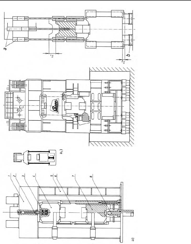
b 1) Principle of the
LASCO counterblow ham-
mer drive with hydraulic
and pneumatic coupling
a) hydraulic cylinder
b) air cylinder
s
1
upper ram stroke
s
2
lower ram stroke
b) LASCO Umformtechnik counterblow
hammer
Figure 22.7
Drive systems of hydraulic counterblow hammers.
a) Bêché & Grohs principle, 1 hydraulic drive, 2
piston rod, 3 ram lock, 4 upper ram, 5 hammer
frame, 6 and 8 piston rods (hydraulic coupling), 7
lower ram: a
1
plan of the hydraulic coupling.

273
As the ram drive is controlled by a single valve, the impact plane (forging plane) is precisely
fixed. The lower ram stroke is about 120 í 150 mm. Its low impact velocity of around 1.2 m/s
means that both flat and complicated forgings lie steady in the die on impact. The resultant
impact velocity is around 6 í 8 m/s.
With these hammers the maximum ram impact velocity is around 8 to 14 m/s. The impact
energy can be determined from the resultant impact velocity of the rams and the ram masses.
Impact energy:
22
12
()
22
mmm
W
XX
W in Nm impact energy
m
1
in kg mass of the upper ram
m
2
in kg mass of the lower ram
X
in m/s final velocity before impact.
In order for the counterblow hammer to open automatically when the machine stops, the lower
ram mass is set about 5 % higher than that of the upper ram. Thus, for hammers with band
couplings
1
2
2.05
2
m
W
X
22.4 Fields of application for hammers
Table 22.2 shows which kinds of hammers are used with different types of impression-die
forging.
Table 22.2 Uses for hammer types
Hammer type Application
Drop hammers small to medium-sized impression-die forgings,
e.g. wrenches, levers, coupling components
Double-acting hammers medium to large-sized impression-die forgings,
(double-column) e.g. camshafts, flanges
Counterblow hammers difficult and extremely difficult impression-die forgings,
e.g. large crankshafts, levers which are hard to form,
large coupling components

274 22 Hammers
22.5 Example
Where:
Drop height H = 1.6 m
Ram mass m = 500 kg
Drop efficiency
K
F
= 0.7
Impact efficiency
K
i
= 0.8.
Find: theoretical ram impact velocity
X
, effective work.
Solution:
Ram impact velocity:
2
2 2 9.81 m/s 1.6 m 5.6 m/sgH
X
The actual impact velocity is lower due to friction losses in the guides.
X
actual
=
K
fr
·
XK
fr
= 0.8 – 0.9
Impact energy:
W = m · q · H ·
K
F
= 500 kg · 9.81 m/s
2
· 1.6 m · 0.7
W = 5493.6 N m
# 5.5 kN m
Effective work:
W
e
=
K
i
· W = 0.8 · 5.5 kN m = 4.4 kNm
If the actual impact velocity is known then the impact energy can also be determined thus:
X
actual
=
K
fr
·
X
= 0.84 · 5.6 m/s = 4.7 m/s
K
fr
= 0.84 selected.
W =
222
3
500 kg 4.7 m / s
5.5 kN m
2
210
m
X
22.6 Exercise on Chapter 22
1. What kinds of hammer frame construction are there?
2. How are hammers classified?
3. What advantages do double-acting hammers have over drop hammers?
4. When are counterblow hammers used?

23 Screw presses
Screw presses are mechanical presses where the ram is moved up and down by a threaded
spindle (usually three-gear). These presses are controlled by energy; the work capacity (avail-
able energy) is the only thing about them which can be directly adjusted. The work capacity
stored in the flywheel comes from its dimensions and rotation speed.
2
sd
d
2302
nI
WI
Z
§·
¨¸
©¹
S
W in Nm work capacity
n
f
in min
–1
flywheel rotation speed
I
d
in kg m
2
mass moment of inertia
30 in s/min conversion of the rotation speed from minutes to seconds
Z
in s
–1
angular velocity
23.1 Forms of structural design
Flywheel construction is categorised:
1. According to the way the flywheel is accelerated:
– friction wheel with disc drive
– hydraulic drive
– direct electric motor drive
– wedge drive
2. According to the way the ram is moved vertically:
– ram moves up and down with spindle and flywheel
– spindle fixed in place with flywheel. Only the ram, shaped like a nut, moves vertically.
This construction is called a Vincent press.
276 23 Screw presses
23.2 Functions of the individual styles of construction
23.2.1 By friction, spindle can be moved axially
The driving discs, turning at a constant
speed (Figure 23.1), can be moved in the
direction of the shaft axis. Thus, one driv-
ing disc at a time can be pressed against the
flywheel using a rod, by hand, with electro-
p
neumatics or hydraulics. By friction, one
driving disc pushes the flywheel with the
threaded spindle and the ram downwards,
while the other disc, turning the opposite
way, pushes them back up. The press col-
umn, made of grey cast iron, is steadied by
steel (e.g. St 60) tie rods. The flywheel,
also made of grey cast iron, has a chrome
leather bracket around it to ensure that
energy is transferred smoothly. The mate-
rial generally used for the press ram is cast
steel.
Figure 23.1
23.2.2 With friction wheel, spindle in fixed position í Vincent presses
Here (Figure 23.2) the spindle is fixed in
p
lace, meaning that the press ram, shaped
like a nut, moves alone axially. With this
Vincent press, the driving discs run on
rolling bearings and are connected by mov-
able tubes coupled to one another (Figure
23.3) in such a way that although the driv-
ing discs act together in the direction o
f
rotation, each disc can be moved independ-
ently laterally. With this press the driving
discs can also be moved laterally by an
adjustment disc to maintain an ideal clear-
ance between the driving discs and the
flywheel even when the bracket wears
down.
If the clearance between the driving disc
and the flywheel was too great, the press
would jerk when started up.
Figure 23.2
23.2 Functions of the individual styles of construction 277
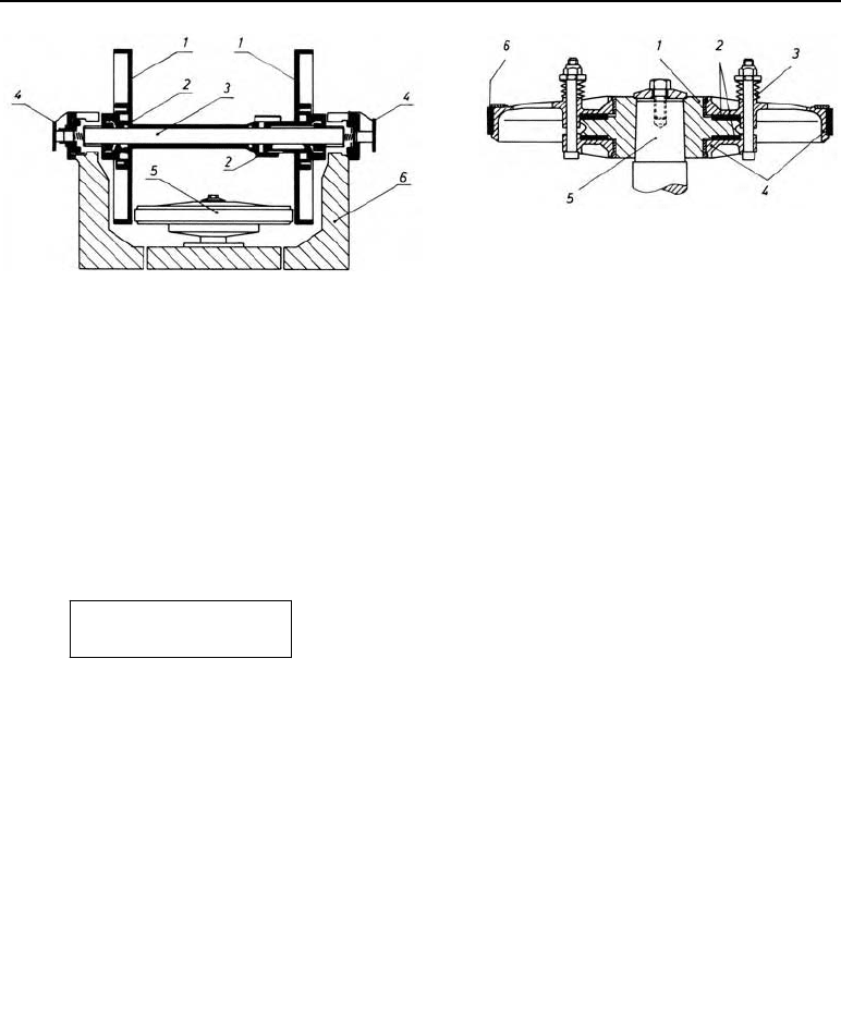
Figure 23.3 Cylinder friction disc gearing on a
Vincent press, 1 driving discs, 2 rolling
bearing, 3 fixed axle, 4 adjusting device, 5
flywheel, 6 press frame (Illustration from
Hasenclever works, Düsseldorf, Germany)
Figure 23.4 Cross-section of a flywheel
with slip clutch (Hasenclever prin-
ciple) 1 fixed section, 2 friction li-
ning, 3 springs, 4 loose section, 5
spindle, 6 bracket
In modern Vincent presses the flywheel (Figure 23.4) is usually designed as a slip wheel. It
contains a spring-loaded slip clutch.
As the press force which occurs is proportional to the moment, the maximum press force can
be limited by adjusting the slip moment optimally (load-limiting device).
tan( )MFr
DU
M in Nm moment
F in N press force
r in m spindle flank radius
D
in deg. pitch angle of the thread
ȡ in deg. angle of friction (about 6° equals
P
= 0.1 for steel on bronze).
On screw presses, maximum 2 · F
N
(F
N
= nominal press force) is allowed for blows with re-
coil.
The press elements (column, spindle etc) are set up for this value.
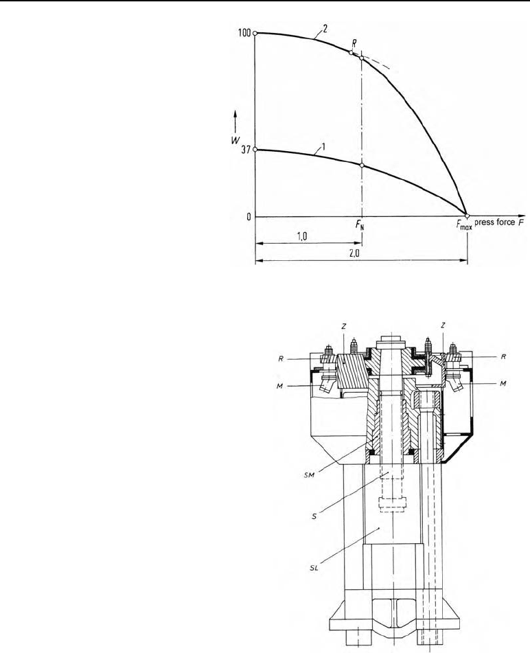
With a slip wheel, the work capacity can be around twice as much as without, so as not to
exceed this limiting value of 2 F
N
. Curve 1 (Figure 23.5) shows the possible energy supply
required not to exceed 2 F
N
on a press without a slip wheel (37%); Curve 2 shows the same
value for the same press with a slip wheel (100%).
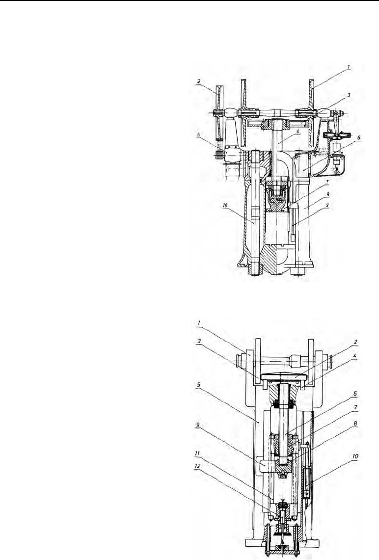
Figure 23.1 (above left) Screw press with three-disc cylinder gears (Kießerling & Albrecht principle)
1 driving disc, 2 wedge-belt pulley, 3 flywheel, 4 spindle, 5 driving motor, 6 head, 7 ram, 8 press column,
9 switch rods, 10 tie rod
Figure 23.2 (below left) Vincent press with three-disc cylinder drive. 1 air pressure cylinder to press the
driving discs, 2 flywheel, 3 driving disc, 4 electro-pneumatic brake, 5 press frame, 6 spindle, 7 spindle
nut, 8 bearing ring, 9 counter-bearing for the upper die, 10 counterweight, 11 ram, 12 ejector (Illustration:
Hasenclever works, Düsseldorf, Germany)
278 23 Screw presses
Figure 23.5
Maximum press force 2 F
N
subject to the
available forming energy W. Curve 1:
press without slip wheel (W only around
1
/
3
of Curve 2) Curve 2: press with slip
wheel
23.2.3 Hydraulically-driven screw presses
On the press shown in Figure 23.6 the fly-
wheel F is a helical gear wheel. The plastic
pinions P (min. 2, max. 8), driven by hydrau-
lic axial piston motors M, mesh with this
helical gearing and accelerate the flywheel to
the required speed. The oil motors are fixed
in the press frame. As the toothed flywheel
moves up and down with the spindle as far as
the stroke length, the pinions slide lengthwise
along the teeth in the flywheel tooth system.
For this reason the flywheel thickness is at
least
press stroke + pinion width.
For the return stroke, the oil motors’ rotation
direction is reversed. The pressurised oil for
the oil motors (210 bar) is prepared in a
p
umping set with axial piston pumps and
stored ready for the next stroke in a hydraulic
storage system. The spindle nut SN is fixed in
the press frame. The spindle S is fixed to the
toothed flywheel F and mounted in the ram R
so that it is able to turn. In this press, the
flywheel is again designed as a slip wheel.
Figure 23.6 Hydraulically-driven screw press.
F flywheel, P pinion, M axial piston
motors, SN spindle nut, S spindle, R
ram (Illustration from Hasenclever
works, Düsseldorf, Germany)

23.2 Functions of the individual styles of construction 279
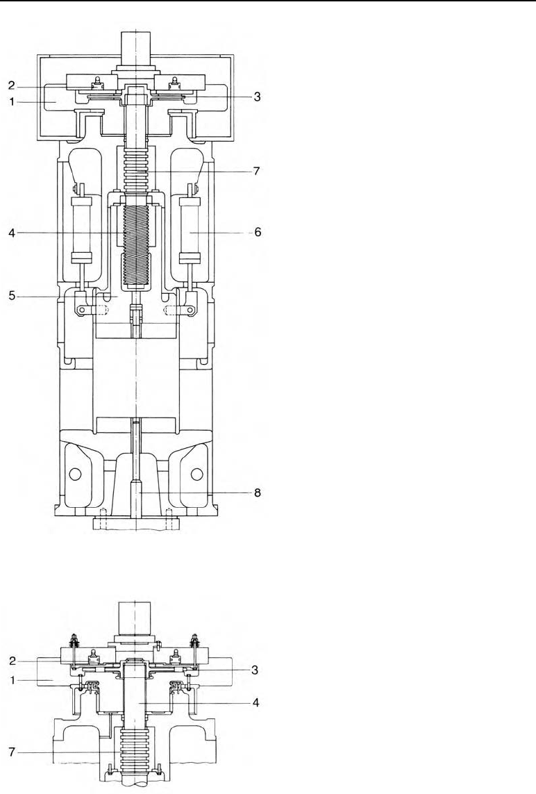
23.2.4 Clutch screw press
In the clutch screw press shown in Figure 23.7 the flywheel turns constantly in one direction
only. It is powered using a flat belt by a three-phase asynchronous motor. For every stroke the
flywheel is loaded on to the spindle and unloaded immediately after the down stroke. When
loaded, the spindle turns and the spindle nut moves the ram down until the upper die comes
into contact with the material and forms it. The flywheel supplies the required forming energy,
losing rotation speed. As soon as the selected pressure between the upper and lower dies has
been reached, the flywheel is unloaded. Two hydraulic cylinders bring the ram back to its
starting position. At the same time they act as a braking device, stopping the ram at the upper
dead centre or in any other stroke position. Furthermore, the cylinders act as counterweights,
meaning that the press can also carry out light blows with only 10% of the nominal press force.
Constructional design
The press frame is a split cast construction held together by four tie rods made of quenched
and tempered steel. The cast steel ram has especially long guides to prevent tipping. The spin-
dle is made of high-alloy quenched and tempered steel. The spindle bearing is a collar bearing
(Figure 23.7a). The spindle nut is made of special bronze. The flywheel is supported hydro-
statically on the press frame.
The clutch between the flywheel and the spindle is a single-disc friction clutch. It is actuated
hydraulically by means of a ring piston. The oil pressure is regulated electronically. When the
selected moment is exceeded the clutch slips out. As the press force is proportional to the spin-
dle moment, the press can also be protected against overload by adjusting the moment.
tanM = F r +
DU
M in Nm moment
F in N press force
r in m spindle flank radius
D
in deg. pitch angle of the thread
U
in deg. angle of friction (about 6° equals
P
= 0.1 for steel on bronze)
The main characteristics of these presses are:
– Low acceleration mass.
Only a light clutch disc and the spindle need to be set into action.
– Short acceleration distance.
Because of the small acceleration mass, the maximum ram velocity is reached after only
1/10 of the stroke.
– Full power is reached after only one-third of the stroke length.
280 23 Screw presses
Figure 23.7
SPK-type clutch screw press
1 flywheel,
2 hydraulic ring piston
3 clutch disc
4 spindle
5 ram
6 return stroke cylinder
7 spindle collar bearing
8 ejector
(Illustration: Hasenclever works, Düsseldorf,
Germany)
Figure 23.7a
Flywheel and spindle clutch
1 flywheel
2 hydraulic ring piston
3 clutch disc
4 spindle
7 spindle collar bearing
(Illustration: SMS Hasenclever works, Düssel-
dorf, Germany)