Stephen L. Herman, Bennie Sparkman. Electricity and Controls for HVAC-R (6th edition)
Подождите немного. Документ загружается.


510 SECTION 8 Solid-State Devices
a lower voltage than the voltage that was applied to
it, assume 5 volts. The diac will remain turned on
until the applied voltage drops below its conduction
level, which in this example is 5 volts. Refer to the
waveform shown in Figure 55–3. Because the diac
is a bidirectional device, it will conduct on either half
cycle of the AC applied to it. Refer to the waveform
shown in Figure 55–4. Notice that the diac has the
same operating characteristic with either half cycle
of AC. The simplest way to sum up the operation of
the diac is to say it is a voltage-sensitive AC switch.
level. For this example, assume this to be 15 volts.
When the voltage reaches 15 volts, the diac will
turn on or re. When the diac res, it displays a
negative resistance, which means it will conduct at
Figure 55–1
Schematic symbols for a diac. (Source: Delmar/Cengage Learning)
Figure 55–2
The diac can operate on either polarity. (Source: Delmar/
Cengage Learning)
+15 VOLTS
+5 VOLTS
Figure 55–3
The diac operates until the applied voltage falls below
its conduction level. (Source: Delmar/Cengage Learning)
+15 VOLTS
+5 VOLTS
–
5 VOLTS
–
15 VOLTS
Figure 55–4
The diac will conduct on either half
of the alternating current.
(Source: Delmar/Cengage Learning)
SUMMARY
The diac is a bidirectional diode.
The primary function of a diac is to phase shift a triac.
The diac operates on AC.
The diac operates like a voltage-sensitive AC switch.
The diac displays a negative resistance characteristic.

UNIT 55 The Diac 511
KEY TERMS
bidirectional
diac
REVIEW QUESTIONS
1. Brie y explain how a diac operates.
2. Draw the two schematic symbols for the diac.
3. What is the major use of the diac in industry?
4. When a diac rst turns on, does the voltage drop, remain at the same level,
or increase to a higher level?

512
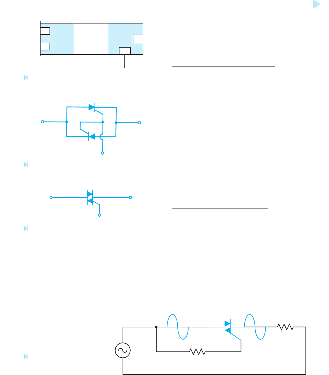
The triac is a PNPN junction connected in parallel
with an NPNP junction. Figure 56–1 illustrates
the semiconductor arrangement of a triac. The triac
operates similar to two SCRs in parallel, facing in
opposite directions with their gate leads connected
together, Figure 56–2. The schematic symbol for
the triac is shown in Figure 56–3.
When an SCR is connected in an AC circuit, the
output voltage will be DC. When a triac is connected
in an AC circuit, the output voltage will be AC.
Since the triac operates like two SCRs connected
together and facing in opposite directions, it will
conduct both the positive and negative half cycles of
AC current.
W
hen a triac is connected in an AC circuit as
shown in Figure 56–4, the gate must be connected
to the same polarity as MT2. When the AC voltage
applied to MT2 become positive, the SCR, which
UNIT 56
The Triac
OBJECTIVES
After studying this unit the student should
be able to:
Draw the schematic symbol for a triac
Discuss the similarities and differences
between SCRs and triacs
Discuss the operation of a triac in an
AC circuit
Discuss phase shifting of a triac
Connect a triac in a circuit
Test a triac with an ohmmeter

UNIT 56 The Triac 513
is forward biased, will conduct. When the voltage
applied to MT2 becomes negative, the other SCR
is forward biased and will conduct that half of the
waveform. Since one of the SCRs is forward biased
for each half cycle, the triac will conduct AC current
as long as the gate lead is connected to MT2.
The triac, like the SCR, requires a certain amount
of gate current to turn it on. Once the triac has been
triggered by the gate, it will continue to conduct
until the current owing through MT2–MT1 drops
below the holding current level.
THE TRIAC USED AS AN AC
SWITCH
The triac is a member of the thyristor family and
has only two states of operation, on or off. When
the triac is turned off it will drop the full applied
voltage of the circuit at 0 amps of current ow.
When the triac is turned on, it has a voltage drop
of about 1 volt and circuit current must be limited
by the load connected to the circuit. The triac
has become very popular in industrial circuits as
an AC switch. Because it is a thyristor, it has the
ability to control a large amount of voltage and
current. There are no contacts to wear out, it is
sealed against dirt and moisture, and it can operate
thousands of times per second. The triac is used as
the output of many solid-state relays that will be
covered later.
THE TRIAC USED FOR AC
VOLTAGE CONTROL
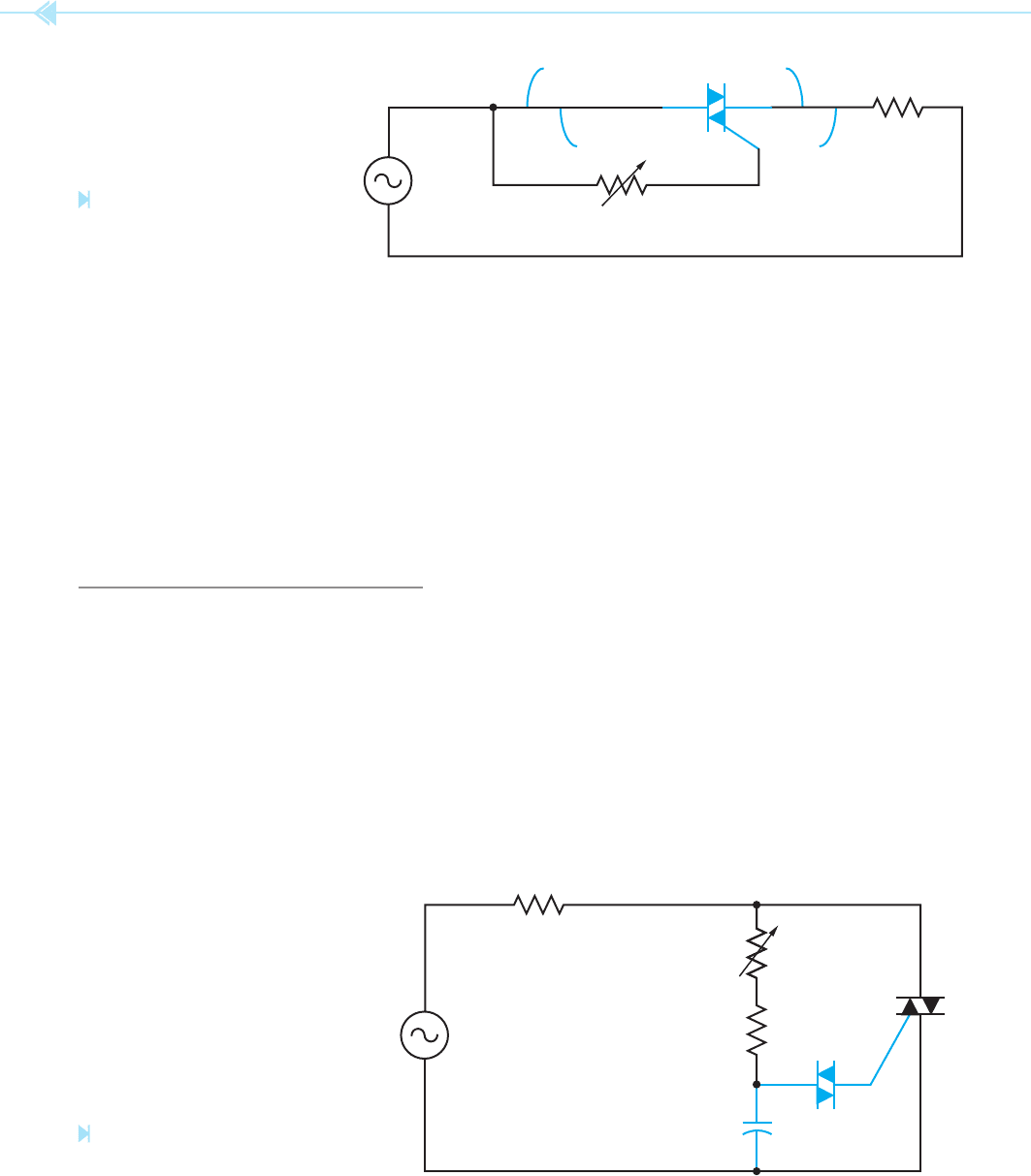
The triac can be used to control an AC voltage,
Figure 56–5. If a variable resistor is connected in
series with the gate, the point at which the gate
current will reach a high enough level to re the
triac can be adjusted. The resistance can be adjusted
to permit the triac to re when the AC waveform
reaches its peak value. This will cause half of the
AC voltage to be dropped across the triac and half to
be dropped across the load.
G
MT1MT2
N
NPNP
N
N
Figure 56–1
Semiconductor arrangement of a triac. (Source: Delmar/
Cengage Learning)
Figure 56–2
The triac operates similar to two SCRs with a common
gate. (Source: Delmar/Cengage Learning)
Figure 56–3
Schematic symbol of a triac. (Source: Delmar/Cengage Learning)
G
MT1MT2
Figure 56–4
The triac will conduct both halves
of the AC waveform. (Source: Delmar/
Cengage Learning)

514 SECTION 8 Solid-State Devices
If the gate resistance is reduced, the amount of
gate current needed to re the triac will be obtained
before the AC waveform reaches its peak value. This
means that less voltage will be dropped across the
triac and more voltage will be dropped across the
load. This circuit permits the triac to control only
one half of the AC waveform applied to it. If a lamp
is used as the load, it can be controlled from half
brightness to full brightness. If an attempt is made
to adjust the lamp to operate at less than half bright-
ness, it will turn off.
PHASE SHIFTING THE TRIAC
The triac, like the SCR, must be phase shifted if
complete voltage control is to be obtained. There
are several methods that can be used to phase shift
a triac, but only one will be covered in this unit.
In this example, a diac will be used to phase shift
the triac, Figure 56–6. In this circuit, resistors R1
and R2 are connected in series with capacitor C1.
Resistor R1 is a variable resistor and is used to
control the charge time of capacitor C1. Resistor
R2 is used to limit current if resistor R1 should be
adjusted to 0 ohms. Assume the diac connected in
series with the gate of the triac will turn on when
capacitor C1 has been charged to 15 volts. When
the diac turns on, capacitor C1 will discharge
through the gate of the triac. This permits the triac
to re or turn on.
Once the triac has red, there will be a voltage
drop of about 1 volt across MT2 and MT1. The triac
will remain turned on until the AC voltage drops to
a low enough value to permit the triac to turn off.
Since the phase shift circuit is connected in parallel
with the triac, once the triac turns on capacitor C1
cannot begin charging again until the triac turns off
at the end of the AC cycle. The diac, being a bidirec-
tional device, will permit a positive or negative pulse
to trigger the gate of the triac.
Notice that the pulse applied to the gate is con-
trolled by the charging of capacitor C1 and not
the amplitude of voltage. If the correct values are
chosen, the triac can be red at any point in the AC
cycle applied to it. The triac can now control the
AC voltage from 0 to the full voltage of the circuit.
MT1MT2
LOAD
Figure 56–5
The triac controls half of the AC
applied voltage. (Source: Delmar/Cengage
Learning)
DIAC
C1
R1
50 KILOHMS
G
MT2
MT1
R2
100 OHMS
1 µf
LOAD
Figure 56–6
Phase-shift circuit for a triac.
(Source: Delmar/Cengage Learning)

UNIT 56 The Triac 515
A common example of this type of triac circuit is the
light dimmer control used in many homes.
TESTING THE TRIAC
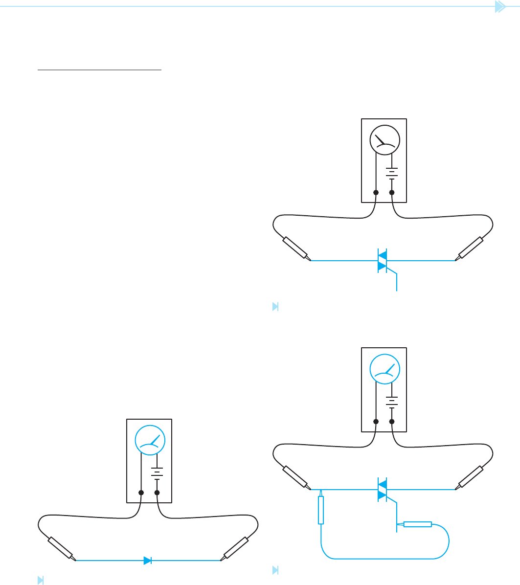
The triac can be tested with an ohmmeter. To test
the triac, connect the ohmmeter leads to MT2 and
MT1. The ohmmeter should indicate no continuity.
If the gate lead is touched to MT2, the triac should
turn on and the ohmmeter will indicate continuity
through the triac. When the gate lead is released
from MT2, the triac may continue to conduct or
turn off depending on whether the ohmmeter sup-
plies enough current to keep the device above its
holding current level. This tests one half of the
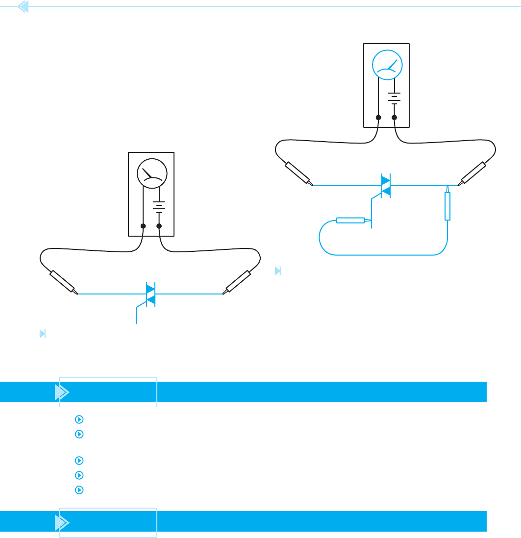
triac. To test the other half of the triac, reverse the
connection of the ohmmeter leads. The ohmmeter
should again indicate no continuity. If the gate is
touched again to MT2, the ohmmeter should indi-
cate continuity through the device. The other half of
the triac has been tested. The following step-by-step
procedure can be used to test a triac.
1. Using a junction diode, determine which
ohmmeter lead is positive and which is nega-
tive. The ohmmeter will indicate continuity
only when the positive lead is connected to
the anode and the negative lead is connected
to the cathode, Figure 56–7.
2. Connect the positive ohmmeter lead to MT2
and the negative lead to MT1. The ohmmeter
should indicate no continuity through the
triac, Figure 56–8.
3. Using a jumper lead, connect the gate of the
triac to MT2. The ohmmeter should indicate
a forward diode junction, Figure 56–9.
ANODE CATHODE
OHMMETER
+–
Figure 56–7
Determining ohmmeter polarity. (Source: Delmar/Cengage Learning)
MT2 MT1
GATE
OHMMETER
+–
Figure 56–8
No continuity. (Source: Delmar/Cengage Learning)
MT2 MT1
GATE
OHMMETER
+–
Figure 56–9
The triac will conduct when the gate is connected
to MT2. (Source: Delmar/Cengage Learning)

516 SECTION 8 Solid-State Devices
SUMMARY
The triac operates in a manner similar to two SCRs connected in opposite directions.
The triac is a bidirectional device, which means that it will operate when connected
to AC current.
Triacs are often used as AC switches.
A triac must be phase shifted to gain complete control of the AC waveform.
A diac is often used to phase shift a triac.
KEY TERM
NPNP
MT2MT1
GATE
OHMMETER
+–
Figure 56–10
Reversing the polarity. (Source: Delmar/Cengage Learning)
MT2MT1
GATE
OHMMETER
+–
Figure 56–11
The triac will conduct with either polarity. (Source: Delmar/
Cengage Learning)
4. Reconnect the triac so that MT1 is connected
to the positive ohmmeter lead and MT2 is
connected to the negative lead. The ohmme-
ter should indicate no continuity through the
triac, Figure 56–10.
5. Using a jumper lead, again connect the gate
to MT2. The ohmmeter should indicate a
forward diode junction, Figure 56–11.

UNIT 56 The Triac 517
1. Draw the schematic symbol of a triac.
2. When a triac is connected in an AC circuit, is the output AC or DC?
3. The triac is a member of what family of devices?
4. Brie y explain why a triac must be phase shifted.
5. What electronic component is frequently used to phase shift the triac?
6. When the triac is being tested with an ohmmeter, which other terminal should the
gate be connected to if the ohmmeter is to indicate continuity?
REVIEW QUESTIONS

518
The operational ampli er has become another
very common component found in industrial elec-
tronic circuits. The operational ampli er,
or op amp
as it is generally referred to, is used in hundreds of
different applications. There are different types of
op amps used, depending on the type of circuit it is
intended to operate in. Some op amps use
bipolar
transistors for the input and others use eld
effect transistors. The advantage of using eld
effect transistors is their extremely high input imped-
ance, which can be several thousand megohms. The
advantage of this extremely high input impedance
is that it does not require a large amount of current
to operate the ampli
er. In fact, op amps, which use
FET inputs, are generally considered as requiring no
input current.
UNIT 57
The
Operational
Amplifi er
OBJECTIVES
After studying this unit the student should
be able to:
Discuss the operation of the
operational amplifi er (op amp)
List the major types of connection for
the op amp
Connect a level detector circuit for an
op amp
Connect an oscillator using an op amp

UNIT 57 The Operational Amplifi er 519
THE IDEAL AMPLIFIER
Before continuing the discussion of op amps, it
should rst be decided what an ideal ampli er
is. First, the ideal ampli er should have an input
impedance of in nity. If the ampli er had an input
impedance of in nity, it would require no power
drain on the signal source being ampli ed. There-
fore, regardless of how weak the input signal source
is, it would not be affected when connected to the
ampli er. The ideal ampli er would have 0 output
impedance. If the ampli er had 0 output imped-
ance it could be connected to any load resistance
desired and not drop any voltage inside the ampli-
er. If it had no internal voltage drop, the ampli er
would utilize 100% of its gain. Third, the ampli er
would have unlimited gain. This would permit it to
amplify any input signal as much as desired.
741 PARAMETERS
There is no such thing as the ideal or perfect ampli-
er of course, but the op amp can come close. One
of the old reliable op amps, which is still used to a
large extent, is the 741. The 741 will be used in this
description as a typical operational ampli er. Please
keep in mind that there are other op amps that have
different characteristics of input and output imped-
ance, but the basic theory of operation is the same
for all of them.
The 741 op amp uses bipolar transistors for the
input. The input impedance is about 2 megohms,
and the output impedance is about 75 ohms. Its
open loop or maximum gain is about 200,000.
Actually, the 741 op amp has such a high gain that
it is generally impractical to use and negative feed-
back, which will be discussed later, is used to reduce
the gain. For instance, assume the ampli er has an
output voltage of 15 volts. If the input signal voltage
is greater than 1/200,000 of the output voltage or
75 microvolts (15/200,00 ⫽ .000075), the ampli-
er would be driven into saturation at which point
it would not operate.
741 PIN CONNECTION
The 741 operational ampli er is generally housed
in an 8-pin in-line IC package, Figure 57–1, Pins #1
and #5 are connected to the offset null. The offset
null is used to produce 0 volts at the output. What
happens is this: The op amp has two inputs called
the inverting input and the noninverting
input. These inputs are connected to a differential
ampli er that ampli es the difference between the
two voltages. If both of these inputs are connected
to the same voltage, say by grounding both inputs,
the output should be 0 volts. In actual practice,
however, there are generally unbalanced conditions
in the op amp that cause a voltage to be produced
at the output. Because the op amp has a very high
gain, a very slight imbalance of a few microvolts at
the input can cause several millivolts at the output.
The offset nulls are adjusted after the 741 is con-
nected into a working circuit. Adjustment is made
by connecting a 10K ohm potentiometer across pins
#1 and #5, and connecting the wiper to the nega-
tive voltage, Figure 57–2.
Pin #2 is the inverting input. If a signal is
applied to this input, the output will be inverted. For
instance, if a positive-going AC voltage is applied
OFFSET NULL 1
741
–
+
INVERTING
INPUT
2
NONINVERTING
INPUT
3
V–
NOT CONNECTED
V
+
OUTPUT
OFFSET NULL4
8
7
6
5
Figure 57–1
741 operational amplifi er.
(Source: Delmar/Cengage Learning)
