Stephen L. Herman, Bennie Sparkman. Electricity and Controls for HVAC-R (6th edition)
Подождите немного. Документ загружается.


490
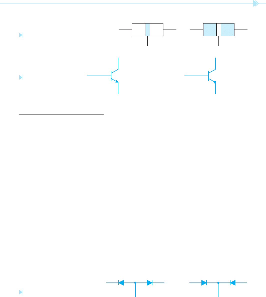
Transistors are made by joining three pieces of
semiconductor material together. There are two
basic types of transistors, the
NPN and the PNP,
Figure 52–1. The schematic symbols for these tran-
sistors are shown in Figure 52–2. The difference in
these transistors is the manner in which they are
connected in a circuit. The NPN transistor must
have positive connected to the
collector and
negative connected to the emitter. The PNP must
have positive connected to the emitter and negative
connected to the collector. Notice that the
base
must be connected to the same polarity as the col-
lector to forward bias the transistor. Also notice that
the arrows on the emitters point in the direction of
conventional current ow.
UNIT 52
The Transistor
OBJECTIVES
After studying this unit the student should
be able to:
Discuss the differences between PNP
and NPN transistors
Test transistors with an ohmmeter
Identify the leads of standard case-
style transistors
Discuss the operation of a transistor
Connect a transistor in a circuit
UNIT 52 The Transistor 491
TESTING THE TRANSISTOR
The transistor can be tested with an ohmmeter.
If the polarity of the output of the ohmmeter leads
is known, the transistor can be identi ed as either
NPN or PNP. A transistor will appear to an ohm-
meter to be two diodes joined together, Figure 52–3.
An NPN transistor will appear to an ohmmeter to
be two diodes with their anodes connected together.
If the positive lead of the ohmmeter is connected to
the base of the transistor, a diode junction should
be seen between the base-collector and the base-
emitter. If the negative lead of the ohmmeter is
connected to the base of an NPN transistor, there
should be no continuity between the base-collector
and the base-emitter junction.
A PNP transistor will appear to be two diodes
with their cathodes connected together. If the nega-
tive lead of the ohmmeter is connected to the base
of the transistor, a diode junction should be seen
between the base-collector and the base-emitter.
If the positive ohmmeter lead is connected to the
base, there should be no continuity between the
base-collector or the base-emitter.
The following step-by-step procedure can be used
to test a transistor.
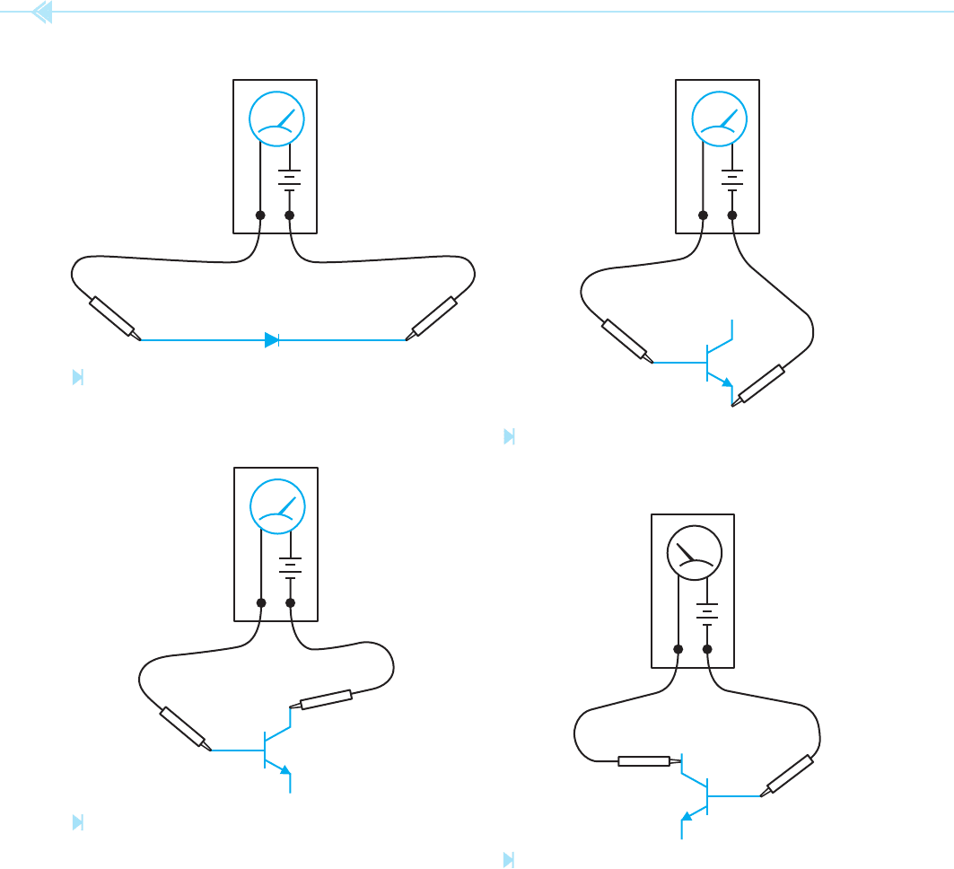
1. Using a diode, determine which ohmmeter
lead is positive and which is negative. The
ohmmeter will indicate continuity through
the diode only when the positive lead is
connected to the anode and the negative lead
is connected to the cathode, Figure 52–4.
2. If the transistor is an NPN, connect the
positive ohmmeter lead to the base and the
negative lead to the collector. The ohm-
meter should indicate continuity. The
reading should be about the same as the
reading obtained when the diode was tested,
Figure 52–5.
3. With the positive ohmmeter lead still con-
nected to the base of the transistor, connect
the negative lead to the emitter. The ohm-
meter should again indicate a forward diode
junction, Figure 52–6.
NOTE: If the ohmmeter does not indicate continu-
ity between the base-collector or the base-emitter,
the transistor is open.
PNN NPP
Figure 52–1
Two basic types of transistors. (Source: Delmar/
Cengage Learning)
+ COLLECTOR
+ BASE
NPN
– EMITTER
– COLLECTOR
– BASE
PNP
+ EMITTER
Figure 52–2
Schematic symbols of
transistors. (Source: Delmar/
Cengage Learning)
COLLECTOR EMITTER
NPN
BASE
COLLECTOR EMITTER
PNP
BASE
Figure 52–3
Ohmmeter test for transistors.
(Source: Delmar/Cengage Learning)
492 SECTION 8 Solid-State Devices
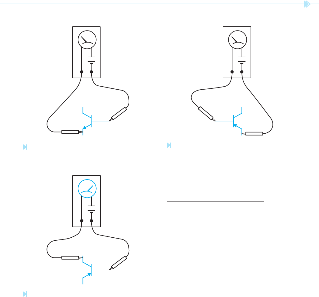
4. Connect the negative ohmmeter lead to the
base and the positive lead to the collector.
The ohmmeter should indicate in nity or no
continuity, Figure 52–7.
5. With the negative ohmmeter lead connected
to the base, reconnect the positive lead to the
emitter. There should, again, be no indication
of continuity, Figure 52–8.
NOTE: If a very high resistance is indicated by the
ohmmeter, the transistor is “leaky” but it may still
operate in the circuit. If a very low resistance is
seen, the transistor is shorted.
6. To test a PNP transistor, reverse the polar-
ity of the ohmmeter leads and repeat the
test. When the negative ohmmeter lead is
ANODE CATHODE
OHMMETER
+–
Figure 52–4
Determining ohmmeter polarity. (Source: Delmar/Cengage Learning)
OHMMETER
+
–
Figure 52–5
Testing the base-emitter junction. (Source: Delmar/
Cengage Learning)
OHMMETER
+
–
Figure 52–6
Testing the base-emitter junction. (Source: Delmar/
Cengage Learning)
OHMMETER
+
–
Figure 52–7
Reversing the connection of the base-collector junction.
(Source: Delmar/Cengage Learning)
UNIT 52 The Transistor 493
should be indicated when the negative lead
is connected to the collector or the emitter,
Figure 52–10.
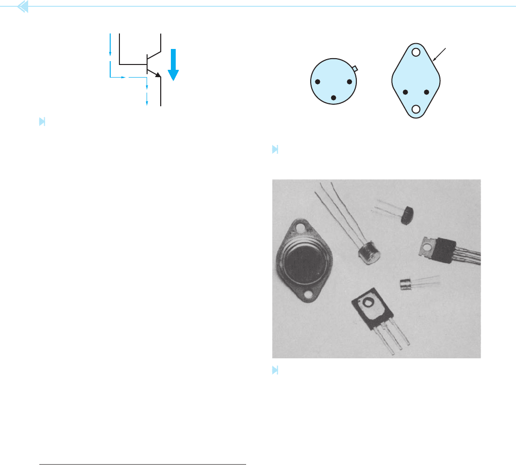
TRANSISTOR OPERATION
The simplest way to describe the operation of a
transistor is to say it operates like an electric valve.
Current will not ow through the collector-emitter
until current ows through the base-emitter. The
amount of base-emitter current, however, is small
when compared to the collector-emitter current,
Figure 52–11. For example, assume that when one
milliamp (mA) of current ows through the base-
emitter junction, 100 mA of current ows through
the collector-emitter junction. If this transistor is a
linear device, an increase or decrease of base current
will cause a similar increase or decrease of collector
current. For instance, if the base current is increased
to 2 mA, the collector current would increase to
200 mA. If the base current is decreased to .5 mA,
the collector current would decrease to 50 mA.
Notice that a small change in the amount of base
current can cause a large change in the amount of
collector current. This permits a small amount of
signal current to operate a larger device, such as the
coil of a control relay.
connected to the base, a forward diode junc-
tion should be indicated when the positive
lead is connected to the collector or emitter,
Figure 52–9.
7. If the positive ohmmeter lead is connected to
the base of a PNP transistor, no continuity
OHMMETER
+
–
Figure 52–8
Reversing the connection of the base-emitter junction.
(Source: Delmar/Cengage Learning)
OHMMETER
+
–
Figure 52–9
Testing the base-collector junction of a PNP transistor.
(Source: Delmar/Cengage Learning)
OHMMETER
+
–
Figure 52–10
Reversing the connection of a PNP transistor. (Source:
Delmar/Cengage Learning)
494 SECTION 8 Solid-State Devices
One of the most common applications of the
transistor is that of a switch. When used in this
manner, the transistor operates like a digital device
instead of an analog device. The term digital refers
to a device that has only two states such as on or
off. An analog device can be adjusted to different
states. An example of this control can be seen in a
simple switch connection. A common wall switch is
a digital device. It can be used to either turn a light
on or off. If the simple toggle switch is replaced with
a dimmer control, the light can be turned on, off, or
adjusted to any position between. The dimmer is an
example of analog control.
If no current ows through the base of the tran-
sistor, the transistor acts like an open switch and
no current will ow through the collector-emitter
junction. If enough base current is applied to the
transistor to turn it completely on, it acts like a
closed switch and permits current to ow through
the collector-emitter junction. This is the same
action produced by the closing contacts of a relay
or motor starter, but a relay or motor starter cannot
turn on and off several thousand times a second and
a transistor can.
IDENTIFYING TRANSISTOR LEADS
Some case styles of transistors permit the leads to
be quickly identi ed. The TO 5 and TO 18 cases,
and the TO 3 case are in this category. The leads of
the TO 5 or TO 18 case transistors can be identi ed
by holding the case of the transistor with the leads
facing you as shown in Figure 52–12A. The metal
tab on the case of the transistor is closest to the emit-
ter lead. The base and collector leads are positioned
as shown in Figure 52–12A.
The leads of a TO 3 case transistor can be identi-
ed as shown in Figure 52–12B. With the transis-
tor held with the leads facing you and down, the
emitter is the left lead and the base is the right
lead. The case of the transistor is the collector.
Several case styles for the transistor are shown in
Figure 52–13.
Figure 52–11
A small base current controls a large collector current.
(Source: Delmar/Cengage Learning)
TO 5 AND
TO 18 CASE
TO 3 CASE
CE
B
(A)
B
C
E
(B)
Figure 52–12
Lead identifi cation of transistors. (Source: Delmar/Cengage Learning)
Figure 52–13
Transistors shown in different case styles. (Source: Delmar/
Cengage Learning)

UNIT 52 The Transistor 495
SUMMARY
Transistors are made by joining three layers of semiconductor material together.
The two basic types of transistors are NPN and PNP.
The three terminal leads of a transistor are the collector, base, and emitter.
A PNP transistor must have a more positive voltage connected to the emitter than the
collector.
An NPN transistor must have a more negative voltage connected to the emitter than
the collector.
The current ow through the base-emitter of the transistor controls the amount of current
ow through collector-emitter.
KEY TERMS
analog
base
case
collector
digital
emitter
NPN
PNP
REVIEW QUESTIONS
1. What are the two basic types of transistors?
2. Explain how to test an NPN transistor with an ohmmeter.
3. Explain how to test a PNP transistor with an ohmmeter.
4. What polarity must be connected to the collector, base, and emitter of an NPN to
make it forward biased?
5. What polarity must be connected to the collector, base, and emitter of a PNP transistor
to make it forward biased?
6. Explain the difference between an analog device and a digital device.

496
The unijunction transistor is a special transis-
tor that has two bases and one emitter. The unijunc-
tion transistor (UJT) is a digital device because it has
only two states, on or off, and is generally classi ed
with a group of devices known as
thyristors.
Thyristors are turned completely on or completely
off. Thyristors include devices such as the silicon-
controlled recti
er (SCR), triac, diac, and the uni-
junction transistor.
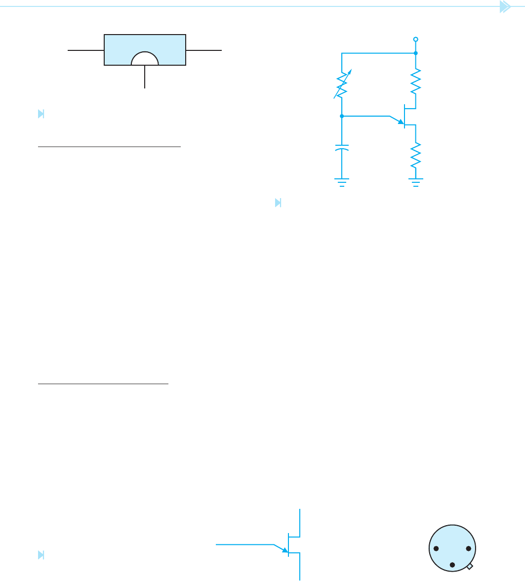
The unijunction transistor is made by combining
three layers of semi-conductor material as shown
in Figure 53–1. The schematic symbol with polar-
ity connections and the base diagram is shown in
Figure 53–2.
UNIT 53
The
Unijunction
Transistor
OBJECTIVES
After studying this unit the student should
be able to:
Discuss the differences between
junction transistors and unijunction
transistors
Identify the leads of a UJT
Draw the schematic symbol for a UJT
Test a UJT with an ohmmeter
Connect a UJT in a circuit
UNIT 53 The Unijunction Transistor 497
UJT CHARACTERISTICS
The UJT has two paths for current ow. One path is
from B2 to B1. The other path is through the emitter
and base #1. In its normal state, there is no current
ow through either path until the voltage applied
to the emitter reaches about 10 volts higher than
the voltage applied to base #1. When the voltage
applied to the emitter reaches about 10 volts more
positive than the voltage applied to base #1, the UJT
turns on and current ows through the B1–B2 path
and from the emitter through base #1. Current will
continue to ow through the UJT until the voltage
applied to the emitter drops to a point that it is only
about 3 volts higher than the voltage applied to B1.
When the emitter voltage drops to this point, the
UJT will turn off and remain turned off until the
voltage applied to the emitter again becomes about
10 volts higher than the voltage applied to B1.
CIRCUIT OPERATION
The unijunction transistor is generally connected
into a circuit similar to the circuit shown in
Figure 53–3. The variable resistor controls the rate
of charge time of the capacitor. When the capaci-
tor has been charged to about 10 volts, the UJT
turns on and discharges the capacitor through the
emitter and base #1. When the capacitor has been
discharged to about 3 volts, the UJT turns off and
permits the capacitor to begin charging again. By
varying the resistance connected in series with the
capacitor, the amount of time needed for charging
the capacitor can be changed, thereby controlling
the pulse rate of the UJT (T ⫽ RC).
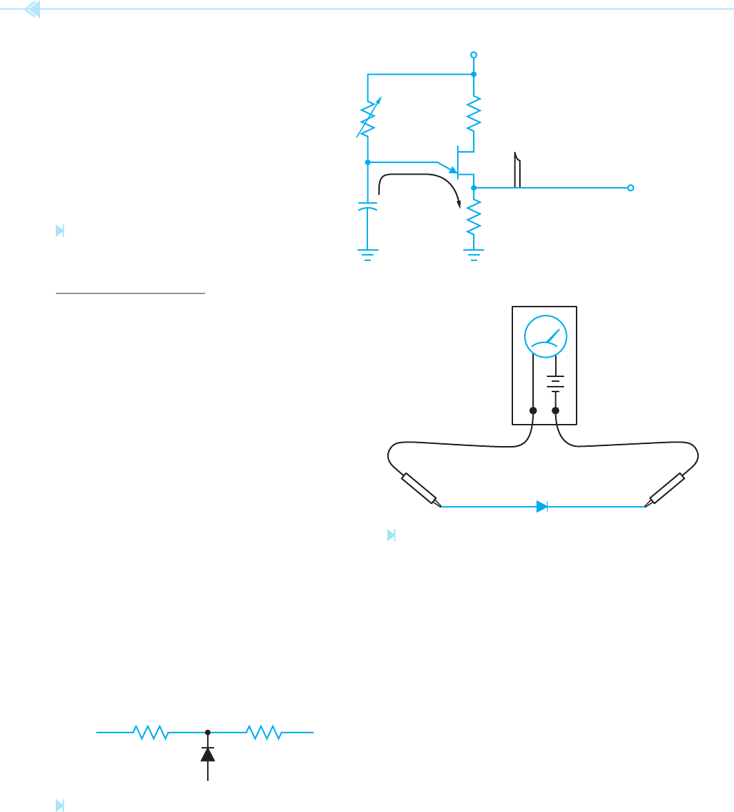
The UJT can furnish a large output pulse, because
the output pulse is produced by the discharging
capacitor, Figure 53–4. This large output pulse is
generally used for triggering the gate of an SCR.
The pulse rate is determined by the amount of
resistance and capacitance connected to the emitter
of the UJT. However, the amount of capacitance that
can be connected to the UJT is limited. For instance,
most UJTs should not have a capacitor larger than
10 μf connected to them. If the capacitor is too large,
the UJT will not be able to handle the current spike
produced by the capacitor, and the UJT could be
damaged.
BOTTOM VIEW
2N2646
B1 B2
E
(B)(A)
BASE #2 (+)
EMITTER (+)
BASE #1 (–)
BASE 2 BASE 1
EMITTER
NN
P
Figure 53–1
Unijunction transistor. (Source: Delmar/Cengage Learning)
Figure 53–2
The schematic symbol for the unijunc-
tion transistor with polarity connec-
tions and base diagram.
(Source: Delmar/
Cengage Learning)
E
B1
B2
+
Figure 53–3
Basic UJT connection. (Source: Delmar/Cengage Learning)
498 SECTION 8 Solid-State Devices
TESTING THE UJT
The unijunction transistor can be tested with an
ohmmeter in a manner very similar to testing a
common junction transistor. The UJT will appear
to the ohmmeter to be a connection of two resis-
tors connected to a common junction diode. The
common junction point of the two resistors will
appear to be at the emitter of the UJT as shown in
Figure 53–5. When the positive lead of the ohm-
meter is connected to the emitter, a diode junction
should be seen from the emitter to base #2 and
another diode connection from the emitter to base
#1. If the negative lead of the ohmmeter is con-
nected to the emitter of the UJT, no connection
should be seen between the emitter and either base.
The following step-by-step procedure can be used
to test a unijunction transistor.
1. Using a junction diode, determine which
ohmmeter lead is positive and which is nega-
tive. The ohmmeter will indicate continuity
when the positive lead is connected to the
anode and the negative lead is connected to
the cathode, Figure 53–6.
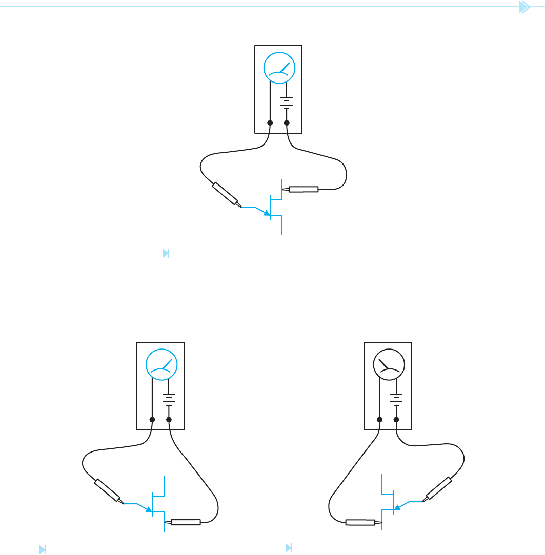
2. Connect the positive ohmmeter lead to the
emitter lead and the negative lead to base #1.
The ohmmeter should indicate a forward
diode junction, Figure 53–7.
3. With the positive ohmmeter lead connected
to the emitter, reconnect the negative lead to
base #2. The ohmmeter should again indi-
cate a forward diode junction, Figure 53–8.
4. If the negative ohmmeter lead is connected to
the emitter, no continuity should be indi-
cated when the positive lead is connected to
base #1 or base #2, Figure 53–9.
E
B1
OUTPUT
B2
+
Figure 53–4
A large pulse is produced by the capacitor
discharge. (Source: Delmar/Cengage Learning)
E
B2 B1
Figure 53–5
The UJT appears as two resistors connected to a diode
when tested with an ohmmeter. (Source: Delmar/Cengage Learning)
ANODE CATHODE
OHMMETER
+–
Figure 53–6
Determining ohmmeter polarity. (Source: Delmar/Cengage Learning)
UNIT 53 The Unijunction Transistor 499
OHMMETER
+
–
B1
B2
E
Figure 53–7
Testing a UJT. (Source: Delmar/Cengage Learning)
OHMMETER
+
B1
B2
E
–
Figure 53–8
Testing the emitter-base 2 junction. (Source: Delmar/
Cengage Learning)
OHMMETER
–
+
B2
B1
E
Figure 53–9
Reversing the polarity.
(Source: Delmar/Cengage Learning)