Stephen L. Herman, Bennie Sparkman. Electricity and Controls for HVAC-R (6th edition)
Подождите немного. Документ загружается.

470 SECTION 8 Solid-State Devices
REVIEW QUESTIONS
1. What type of resistor is generally used when a high power rating is needed?
2. What type of wire is generally used in the construction of resistors intended to be oper-
ated at high temperatures?
3. A resistor is marked orange, orange, orange, and gold. An ohmmeter indicates that
the resistor value is 34,700 ohms. Is this resistor within its tolerance rating?
4. What would be the color bands for a 1,000-ohm resistor with a tolerance of ⫾2%?
5. What would be the color bands for a resistor valued at 365,000 ohms?
6. A resistor has color bands of yellow, orange, gold, gold. What is the value and
tolerance of this resistor?
that the chances of failure become much smaller.
The military often employs companies to test resis-
tors for some period of time by operating them in
a circuit and then checking the value to see if the
resistor has remained within its tolerance rating.
SUMMARY
Wire wound resistors are generally used for applications requiring a high power rating.
Nichrome wire is generally employed in the construction of wire wound resistors.
Electric heating elements are generally made of nichrome wire.
Resistors in sizes ranging from
1
/8 to 2 watts generally have their values marked with
bands of color.
The size of a resistor is generally an indication of its power rating.
A resistor color code is generally used to indicate a resistor’s ohmic value and tolerance.
Resistors that have only three bands of color are rated at ⫾20%.
Resistors with a tolerance rating of ⫾2%, ⫾5%, and ⫾10% have four color bands.
Resistors with a tolerance rating ⫾1% have a brown fth band.
The fth band of some military resistors indicates reliability.
KEY TERMS
bands of color
xed resistors
nichrome
tolerance
wattage rating
wire wound
Resistors with a fth band of yellow are rated reli-
able enough for space ight equipment. An orange
fth band indicates the resistor is reliable enough for
use in missile systems. A white fth band indicates
the leads are solderable.

UNIT 48 Resistors and Color Codes 471
7. What color bands would be found on a resistor with an ohmic value of 510 ⍀ and a
tolerance of ⫾10%?
8. Should a wire wound resistor with a hollow core be mounted vertically or
horizontally?
9. A wire wound resistor has a value of 100 ⍀ and a power rating of 150 watts. If this
resistor is connected to 120 volts, will its power rating be exceeded?
10. A circuit requires a resistor with a value of 5,000 ohms. What is the closest standard
value of a 5% resistor that can be used in this circuit?

472
Many of the air conditioning controls are oper-
ated by solid-state devices as well as magnetic and
mechanical devices. If a service technician is to
install and troubleshoot control systems, he or she
must have an understanding of electronic devices
as well as relays.
Solid-state devices, such as diodes and transistors,
are often referred to as
semiconductors. The word
semiconductor refers to the type of material solid-state
devices are made of. To understand how solid-state
devices operate, one must study the atomic structure
of conductors, insulators, and semi conductors.
CONDUCTORS
Conductors are materials that provide an easy path
for electron ow. Conductors are generally made from
materials that have large, heavy atoms. This is why
OBJECTIVES
After studying this unit the student should
be able to:
Discuss the atomic structure
of conductors, insulators, and
semiconductors
Discuss how a P-type material
is produced
Discuss how an N-type material
is produced
Semiconductor
Materials
UNIT 49
UNIT 49 Semiconductor Materials 473
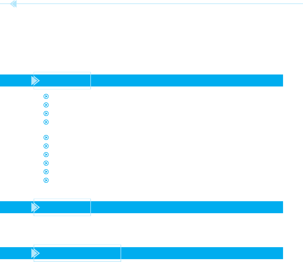
most conductors are metals. The best electrical con-
ductors are silver, copper, and aluminum. Conduc-
tors are materials that have only one or two valence
electrons in their atom, Figure 49–1. An atom that
has only one valence electron makes the best electri-
cal conductor because the electron is loosely held in
orbit and is easily given up for current ow.
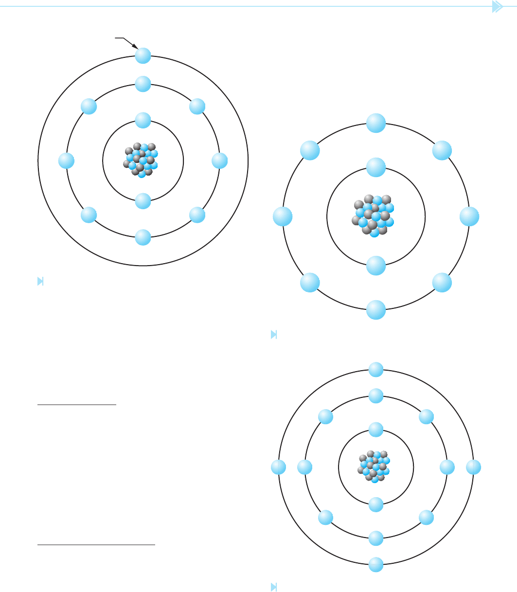
INSULATORS
Insulators are generally made from light-weight
materials that have small atoms. The atoms of an
insulating material will have their outer orbits lled
or almost lled with valence electrons. This means
an insulator will have seven or eight valence elec-
trons, Figure 49–2.
Because an insulator has its outer orbit lled or
almost lled with valence electrons, they are tightly
held in orbit and not easily given up for current ow.
SEMICONDUCTORS
Semiconductors, as the name implies, are materials
that are neither good conductors nor good insula-
tors. Semiconductors are made from materials that
Valence Electron
Figure 49–1
Atom of a conductor. (Source: Delmar/Cengage Learning)
Figure 49–2
Atom of an insulator. (Source: Delmar/Cengage Learning)
Figure 49–3
Atom of a semiconductor.
(Source: Delmar/Cengage Learning)
have four valence electrons in their outer orbit,
Figure 49–3.
The most common semiconductor materials
used in the electronics eld are germanium and
silicon. Of these two materials, silicon is used
474 SECTION 8 Solid-State Devices
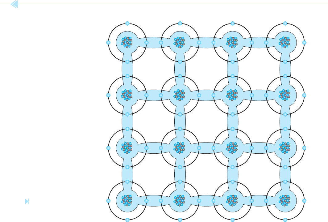
Figure 49–4
Lattice structure of a pure
semiconductor material.
(Source: Delmar/Cengage Learning)
more often because of its ability to withstand heat.
When semiconductor materials are re ned into
a pure form, the molecules arrange themselves
into a crystal structure that has a de nite pattern,
Figure 49–4. A pattern such as this is known as a
lattice structure.
A pure semiconductor material such as silicon
has no special properties and will do little more than
make a poor conductive material. If a semiconduc-
tor material is to become useful for the production
of solid-state components, it must be mixed with
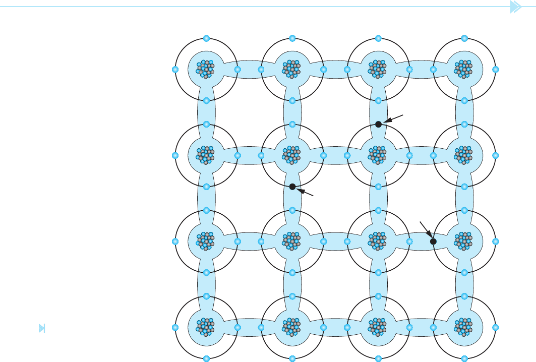
an impurity. When the semiconductor material is
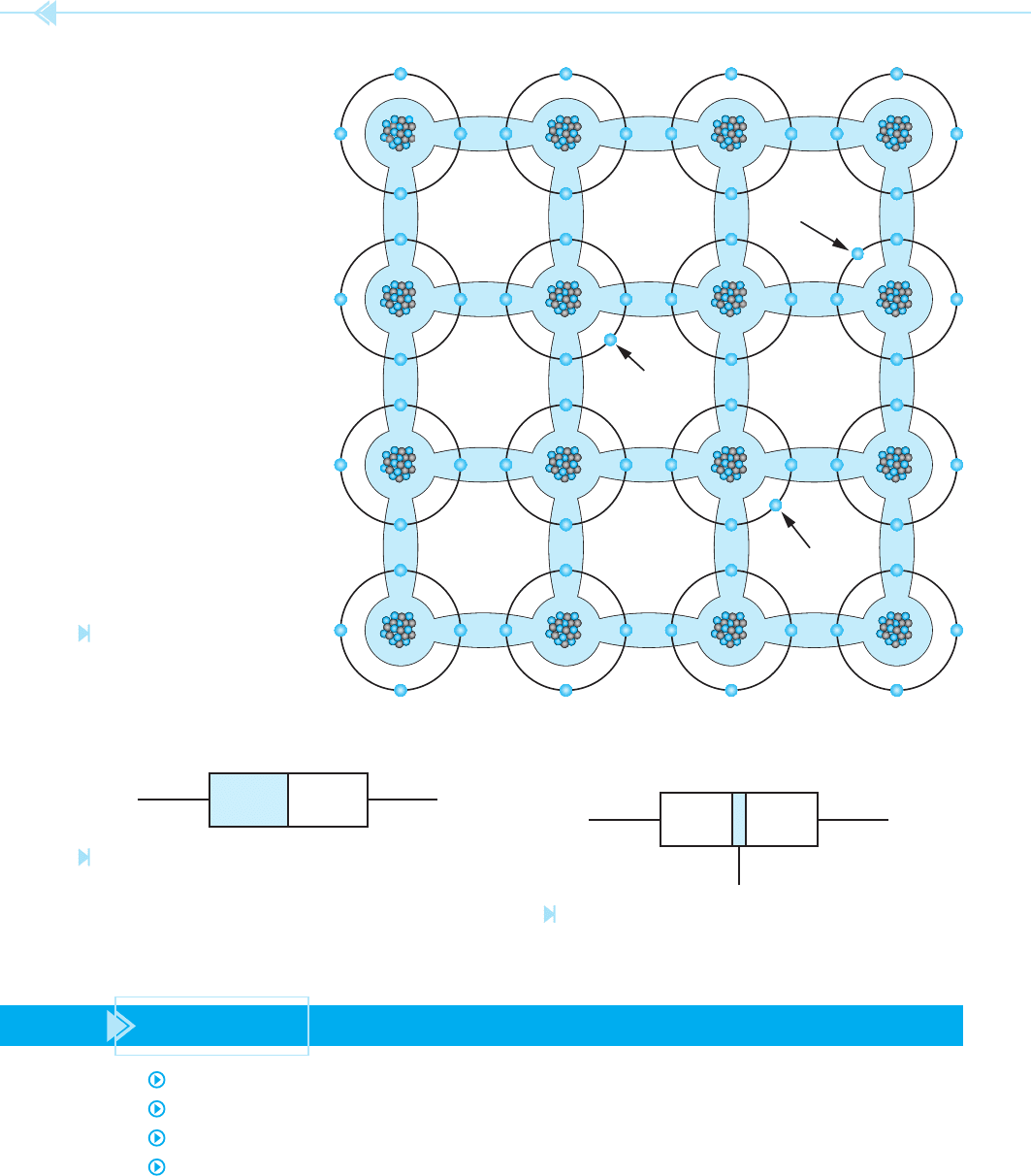
mixed with an impurity that has only 3 valence
electrons, such as idium or gallium, the lattice struc-
ture also becomes different, Figure 49–5. When a
material that has only 3 valence electrons is mixed
with a pure semiconductor, a hole is left in the mate-
rial when the lattice structure is formed. This hole is
caused by the lack of an electron where one should
be. Because the material now has a lack of elec-
trons, it is no longer electrically neutral. Electrons
are negative particles. Because a hole is in a place
where an electron should be, the hole has a positive
charge. This semiconductor material now has a net
positive charge, and is therefore known as a
P-type
material.
UNIT 49 Semiconductor Materials 475
Figure 49–5
Lattice structure of a P-type
material. (Source: Delmar/Cengage
Learning)
Hole
Hole
Hole
When a semiconductor material is mixed with an
impurity that has 5 valence electrons, such as arse-
nic or antimony, the lattice structure will have an
excess of electrons, Figure 49–6. Because electrons
are negative particles, and there are more electrons
in the material than there should be, the material
has a net negative charge. This material is referred
to as an N-type material because of its negative
charge.
All solid-state devices are made from a combina-
tion of P- and N-type materials. The type of device
formed is determined by how the P- and N-type
materials are connected or joined together. The
number of layers of material and the thickness of
various layers play an important part in determin-
ing what type of device will be formed. For instance,
the diode is often called a PN junction because it is
made by joining together a piece of P-type and a
piece of N-type material, Figure 49–7.
The transistor, on the other hand, is made by
joining three layers of semiconductor material,
Figure 49–8. Regardless of the type of solid-state
device being used, it is made by the joining together
of P- and N-type materials.
476 SECTION 8 Solid-State Devices
PN
Free Electron
Free Electron
Free Electron
Figure 49–6
Lattice structure of an N-type
material. (Source: Delmar/Cengage
Learning)
P
NN
Figure 49–7
PN junction. (Source: Delmar/Cengage Learning)
Figure 49–8
Transistor. (Source: Delmar/Cengage Learning)
SUMMARY
Conductors are materials that provide an easy path for electron ow.
The best conductors are silver, copper, and aluminum.
Valence electrons are electrons located in the outermost orbit or shell of an atom.
Conductors are made from materials that generally contain 1 or 2 valence electrons.

UNIT 49 Semiconductor Materials 477
Insulators are materials that do not conduct electricity easily.
Insulators are made from materials that generally contain 7 or 8 valence electrons.
Semiconductors are materials that contain 4 valence electrons.
The two most common semiconductor materials are germanium and silicon.
Silicon is used more often than germanium because it can withstand more heat.
P-type material is made by combining a material that has 3 valence electrons with a pure
semiconductor material.
A P-type semiconductor material has an excess of holes in its structure.
N-type material is made by combining a material that has 5 valence electrons with a pure
semiconductor material.
N-type semiconductor material has an excess of electrons in its structure.
KEY TERMS
germanium
lattice structure
N-type material
P-type material
semiconductors
silicon
REVIEW QUESTIONS
1. How many valence electrons are contained in a material used as a conductor?
2. How many valence electrons are contained in a material used as an insulator?
3. What are the two most common materials used to produce semiconductor devices?
4. What is a lattice structure?
5. How is a P-type material made?
6. How is an N-type material made?
7. What type of semiconductor material can withstand the greatest amount of heat?
8. All solid-state components are formed from combinations of P- and N-type materials.
What factors determine what kind of components will be formed?

478
As stated previously, solid-state devices are made
by combining P- and N-type materials together.
The device produced is determined by the number
of layers of material used, the thickness of the lay-
ers of material, and the manner in which the layers
are joined together. Hundreds of different electronic
devices have been produced since the invention of
solid-state components.
It is not within the scope of this text to cover even
a small portion of these devices. The devices to be
covered by this text have been chosen because of
their frequent use in the air conditioning industry
as opposed to communications or computers. These
devices are presented from a straightforward, prac-
tical viewpoint, and mathematical explanation is
used only when necessary.
The PN junction is often referred to as the
diode.
The diode is the simplest of all electronic devices.
OBJECTIVES
After studying this unit the student should
be able to:
Discuss how the PN junction
is constructed
Recognize the schematic symbol for
a diode
Discuss the differences between the
conventional current fl ow theory and
the electron fl ow theory
Discuss how the diode operates in
a circuit
Identify the anode and cathode leads
of a diode
Properly connect the diode in an
electric circuit
Discuss the differences between a half-
wave rectifi er and a full-wave rectifi er
Test the diode with an ohmmeter
The PN
Junction
UNIT 50
UNIT 50 The PN Junction 479
Figure 50–1
PN junction.
(Source: Delmar/Cengage Learning)
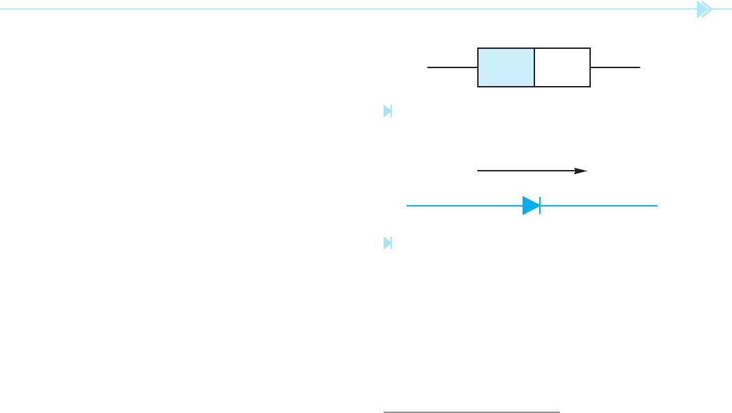
Figure 50–2
Schematic symbol of a diode. (Source: Delmar/Cengage Learning)
It is made by joining together a piece of P-type
material and a piece of N-type material. Refer to
Figure 50–1. The schematic symbol for a diode is
shown in Figure 50–2. The diode operates like an
electric check valve in that it will permit current to
ow through it in only one direction. If the diode is
to conduct current, it must be
forward biased.
The diode is forward biased only when a positive
voltage is connected to the anode and a negative
voltage is connected to the
cathode. If the diode is
reverse biased, the negative voltage connected
to the anode and the positive voltage connected to
the cathode, it will act like an open switch and no
current will
ow through the device.
One thing the service technician should be aware
of when working with solid-state circuits is that the
explanation of the circuit is often given assuming
conventional current ow as opposed to electron
ow.
The conventional current ow theory
assumes that current ows from positive to negative
as opposed to the
electron ow theory, which
states that current ows from negative to positive
.
Although it has been known for many years that
current ows from negative to positive, many of the
electronic circuit explanations assume a positive
to negative current ow. There are several reasons
for this. For one, ground is generally negative and
considered to be 0 volts in an electronic circuit. Any
voltage above or greater than ground is positive.
Most people nd it is easier to think of something
owing downhill or from some point above to some
point below. Another reason is that all the arrows in
an electronic schematic are pointed in the direction
of conventional current ow. The diode shown in
Figure 50–2 is forward biased only when a positive
voltage is applied to the anode and a negative volt-
age is applied to the cathode. If the conventional
current ow theory is used, current will ow in
the direction the arrow is pointing. If the electron
theory of current ow is used, current must ow
against the arrow.
A common example of the use of the conven-
tional current ow theory is the electrical systems
of automobiles. Most automobiles use a negative
ground system, which means the negative terminal
of the battery is grounded. The positive terminal of
the battery is considered to be the “HOT” terminal,
and it is generally assumed that current ows from
PN
ANODE CATHODE
+–
the “HOT” to ground. This explanation is offered in
an effort to avoid confusion when troubleshooting
electronic circuits.
TESTING THE DIODE
The diode can be tested with an ohmmeter. When
the leads of an ohmmeter are connected to a
diode, the diode should show continuity in only
one direction. For example, assume that when the
leads of an ohmmeter are connected to a diode, it
shows continuity. If the leads are reversed, the ohm-
meter should indicate an open circuit. If the diode
shows continuity in both directions, it is shorted.
If the ohmmeter indicates no continuity in either
direction, the diode is open. To test the diode, follow
this two-step procedure:
1. Connect the ohmmeter leads to the diode.
Notice if the meter indicates continuity
through the diode or not, Figure 50–3.
2. Reverse the diode connection to the ohm-
meter, Figure 50–4. Notice if the meter
indicates continuity through the diode or not.
The ohmmeter should indicate continuity
through the diode in only one direction.
NOTE: If continuity is not indicated in either
direction, the diode is open. If continuity is indi-
cated in both directions, the diode is shorted.