Stephen L. Herman, Bennie Sparkman. Electricity and Controls for HVAC-R (6th edition)
Подождите немного. Документ загружается.


440 SECTION 7 Ice Maker and Refrigeration Controls
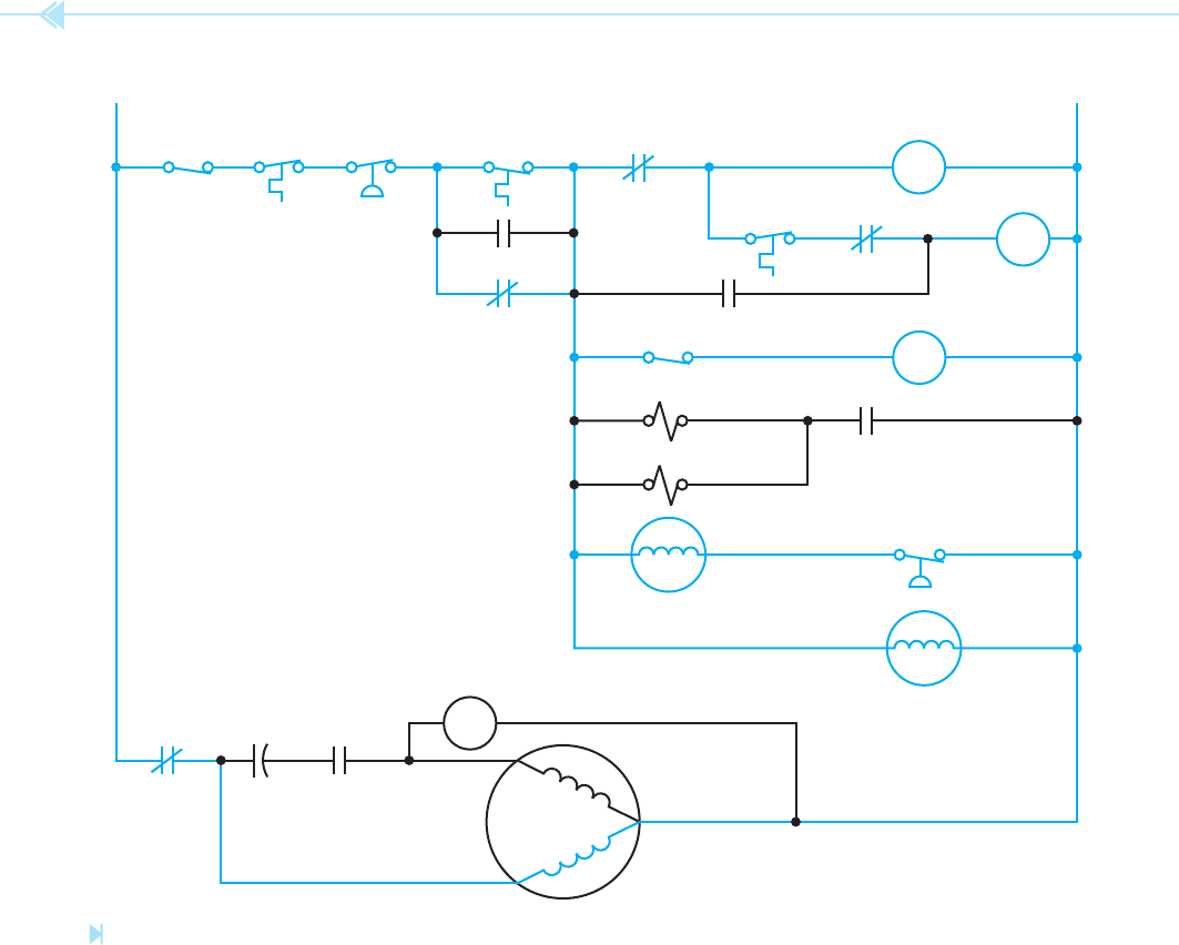
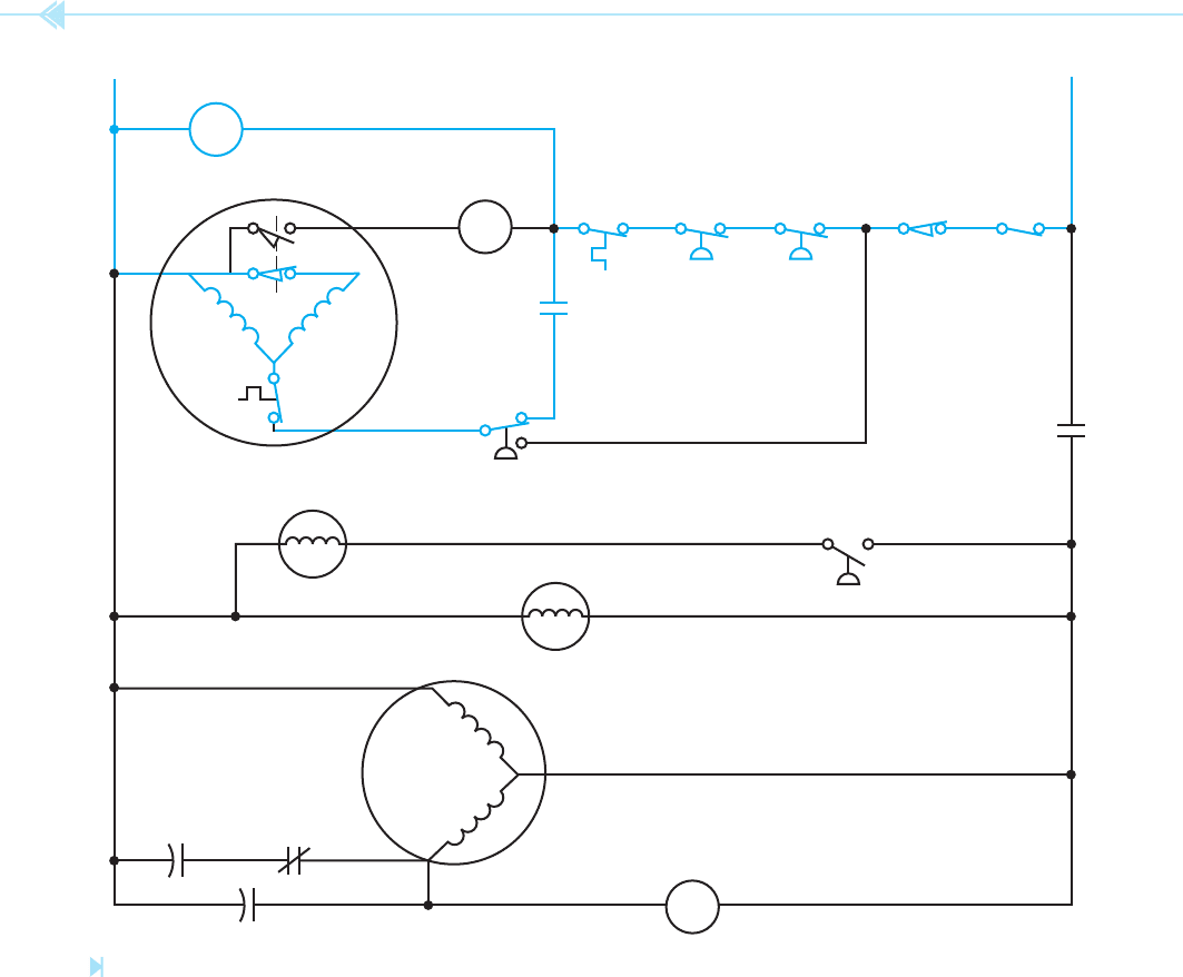
After the circuit has operated in this condition for
some period of time, the evaporator plate becomes
cold enough to permit the cube-size thermostat
to close as shown in Figure 46–5. This completes
a circuit to the timer motor. The timer is used to
complete the cycle in the event the bin thermostat
should open.
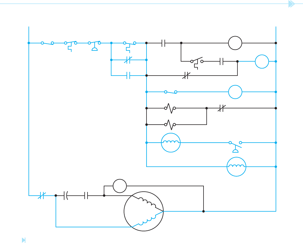
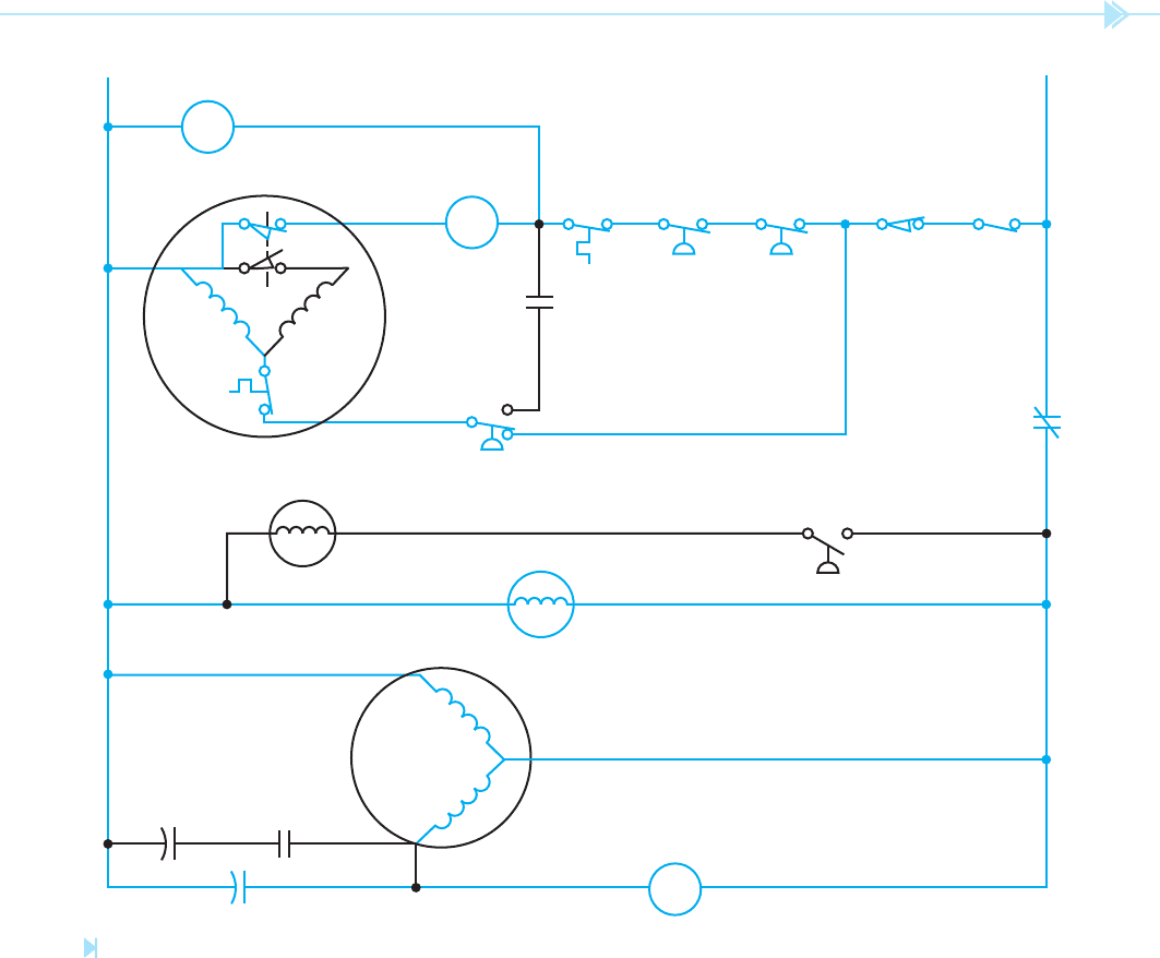
After the timer has operated for some length of
time, the timer contacts will change position as
shown in Figure 46–6, starting the harvest cycle.
The TMR2 contact closes to maintain a current path
around the bin thermostat contact, and the TMR1
contact opens and deenergizes coil FR. When coil FR
deenergizes, all of its contacts return to their normal
position. The FR2 contact recloses and maintains
a current path to the timer motor, permitting it
to complete the cycle. When the FR4 contact re-
closes, the hot-gas solenoid and water solenoid
valves open. As hot gas is circulated through the
evaporator plate, it warms and permits the cube
size thermostat contact to reopen. The circuit will
continue to operate in this condition until the timer
completes the cycle and resets both TMR contacts.
At this point, the freeze cycle will begin again if the
bin thermostat is still closed.
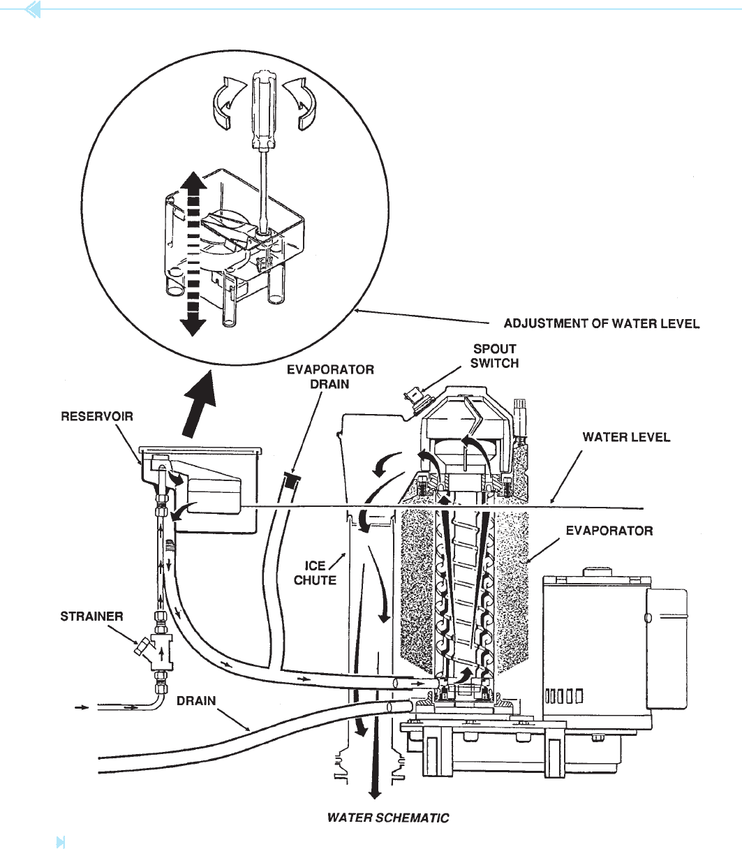
FLAKER-TYPE ICE MAKERS
Flaker-type ice makers produce ice continuously
as opposed to harvesting ice cubes at certain inter-
vals. Flaked ice has a soft,
aky texture and is often
preferred by restaurants. A basic diagram of a
aker-type ice maker is shown in Figure 46–7. The
water supply from the building enters the water
reservoir. A oat valve maintains a constant water
level in the reservoir.
Water from the reservoir enters the bottom of
the
freezer assembly. The freezer assembly is
the evaporator of the refrigeration unit. The freezer
assembly is basically a hollow tube surrounded by
a cylindrical container. Refrigerant is used to cool
the hollow tube. A stainless steel
auger is placed
inside the hollow tube. The motor drive assembly
turns the auger. As water enters the bottom of the
freezer assembly, it is frozen into ice and carried
upward by the auger. When the ice reaches the top,
the
ared end of the auger presses excess water out
of the ice before it is extruded or aked out through
switch, and can be used to disconnect power to the
entire control circuit. The second is connected in
series with the compressor contactor relay coil. This
switch can be used to turn off the compressor sepa-
rately. Two safety switches, the high temperature
cutout and the high pressure cutout, are connected
in series with the master switch. If either of these
switches opens, they will disconnect power to the
control circuit.
This circuit also contains two thermostats, the
bin
thermostat and the cube-size thermostat.
The sensor for the bin thermostat is located in the ice
storage bin and senses the level of ice. When the ice
reaches a high enough level, it touches the sensor and
causes the contact to open. This stops the operation
of the ice maker at the end of the harvest cycle. The
sensor for the cube-size thermostat is mounted on the
evaporator plate. When the evaporator plate reaches
a low enough temperature, the thermostat contact
closes and completes a circuit to the timer motor. The
timer contains a set of cam-operated contacts and is
used to complete the freeze and harvest cycle.
This circuit also contains a fan motor controlled
by a pressure switch that senses the pressure on the
high side of the compressor. This fan motor is used
only on units with an air-cooled condenser. Because
this fan motor is controlled by a pressure switch, it
may cycle on and off during the unit’s operation.
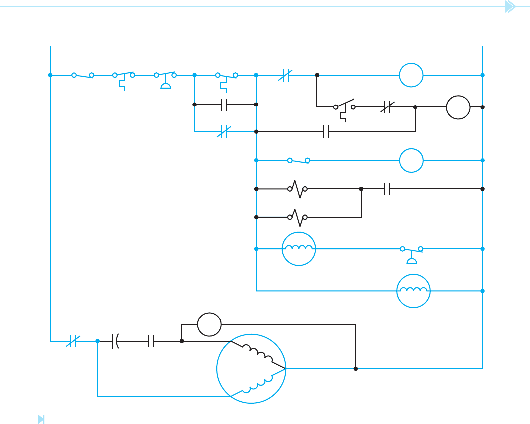
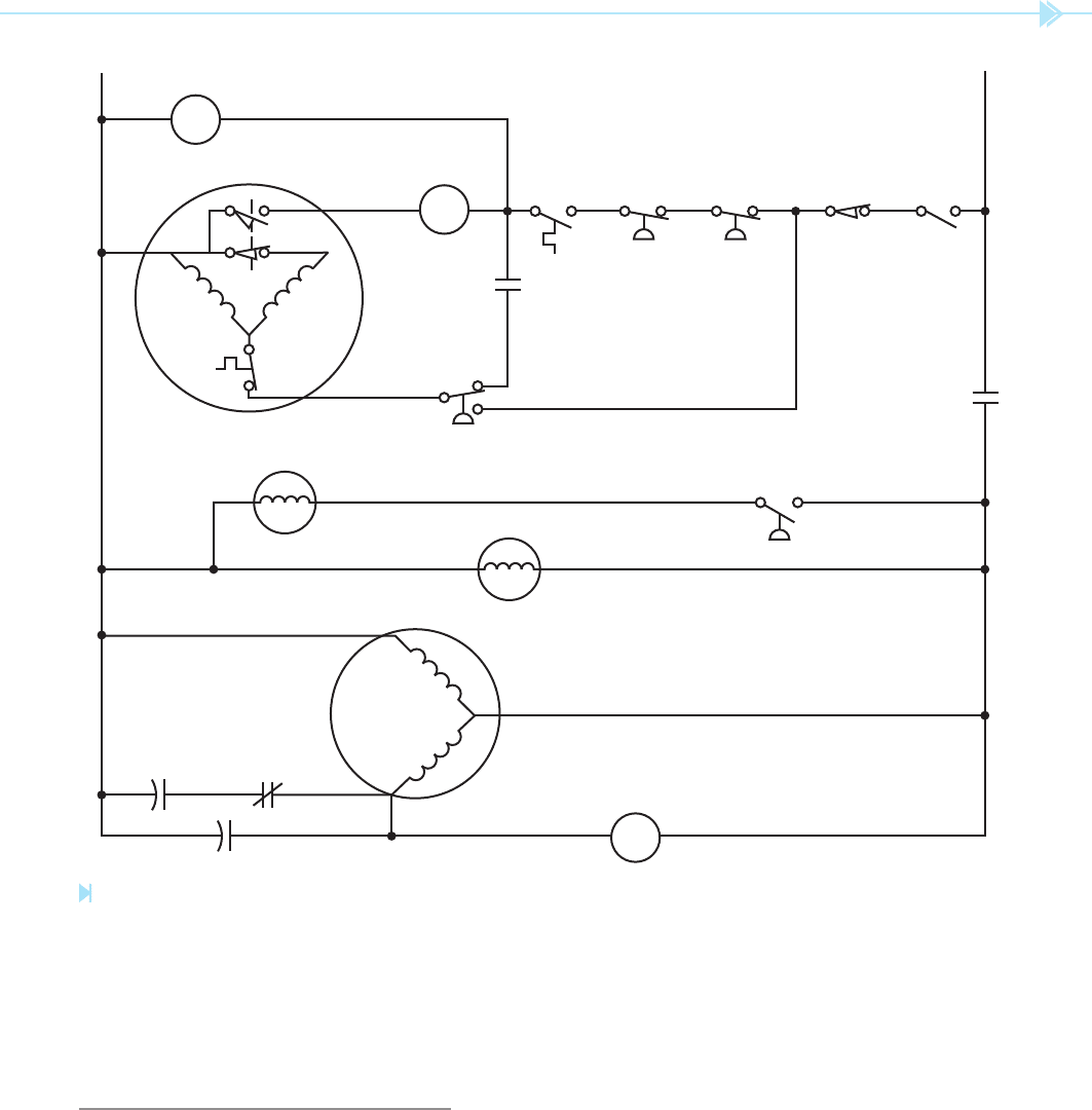
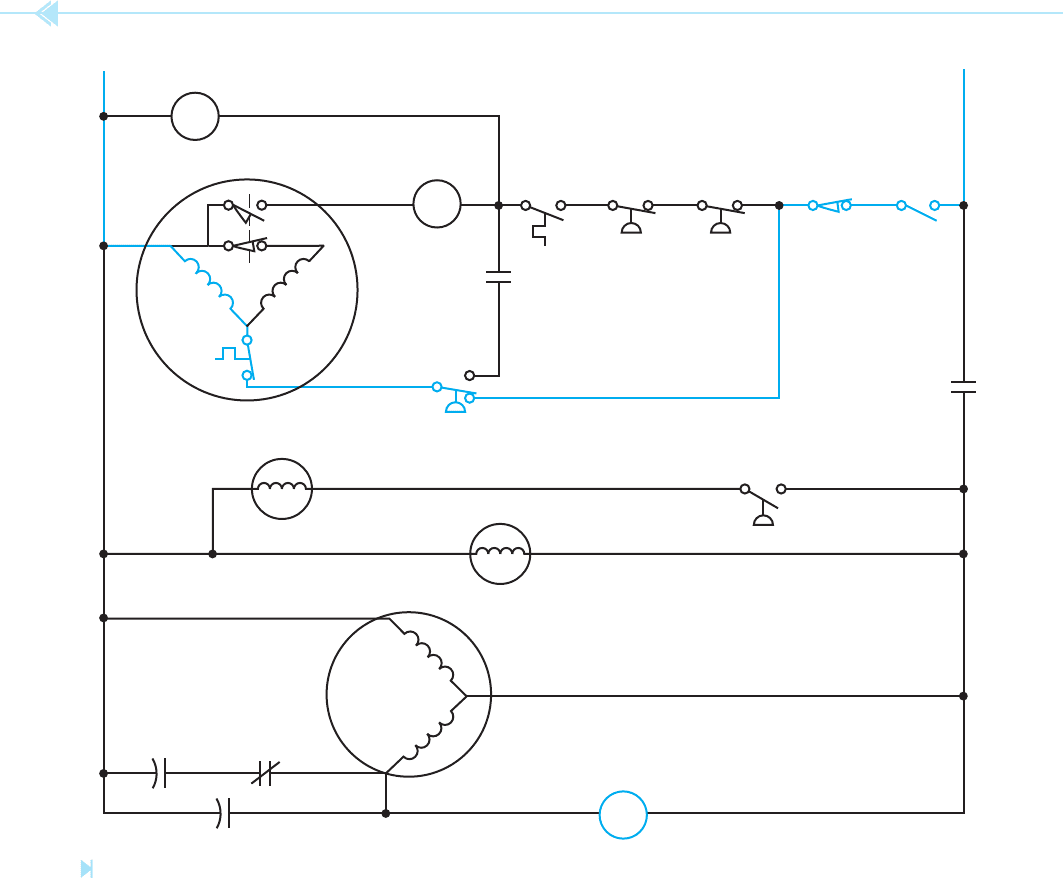
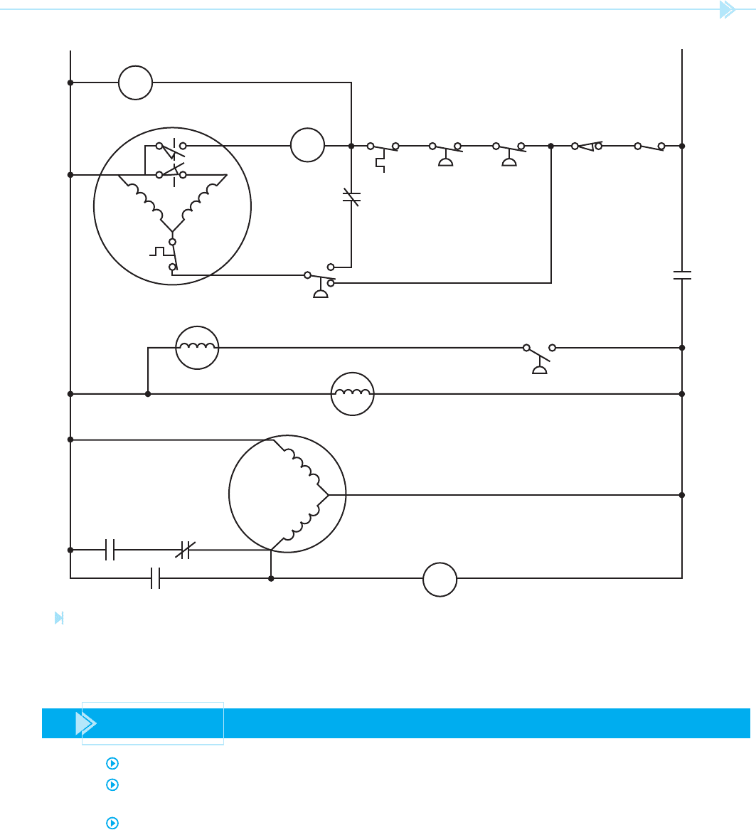
For a better understanding of this circuit, it
is shown at the beginning of the freeze cycle,
Figure 46–4. It is assumed that the master switch
and the compressor switch have been closed, and
that the bin thermostat contact is closed. A circuit
is now completed to the nish relay, FR, causing all
FR contacts to change position. The FR3 contact
serves as a holding contact to permit completion
of the cycle in the event the bin thermostat contact
should open. The FR1 contact has closed to permit a
current path to the timer motor when the cube size
thermostat closes. The compressor contactor coil is
energized, which closes its contact and connects the
compressor to the line. The pump motor is energized
causing water to ow over the evaporator plate. It
is also assumed that the high-pressure fan control
switch is closed, permitting the condenser fan motor
to operate. Notice, however, that the FR4 contact
has opened to prevent the hot-gas solenoid and the
water solenoid from operating.
UNIT 46 Commercial Ice Markers 441
switches, one normally closed and the other nor-
mally open. The normally closed switch connects
the motor start winding to the line when the motor
is started. The normally open centrifugal switch con-
trols the coil of the compressor contactor. The com-
pressor contactor can be energized only when the
auger drive motor operates within a certain speed
range. If ice becomes compacted in the freezer unit,
it will cause the auger drive motor to slow down. If
the speed of the auger drive motor is reduced below
a certain point, the centrifugal switch connected in
the ice spout. A nylobraid tube carries the ice to
the ice storage bin. When enough ice accumulates,
it touches the sensor bulb of the bin thermostat. The
bin thermostat contact then opens and the compres-
sor is disconnected from the line, but the auger drive
motor continues to operate for approximately 1 to
2 minutes. This permits the auger to clear the ice
out of the freezer unit before it stops operating.
The basic schematic diagram for the aker-type
ice maker is shown in Figure 46–8. Notice that the
auger drive motor contains two separate centrifugal
PUMP MOTOR
COMPRESSOR
START
RUN
HIGH
TEMP.
CUTOUT
HIGH
PRESS.
CUTOUT
MASTER
SWITCH
L1 N
FAN MOTOR
HIGH PRESS.
FAN CONTROL
PSR
POTENTIAL
STARTING
RELAY
PSRC
START CAP.
FR2
HOT GAS SOL.
WATER SOL.
TMR1
BIN
THERMOSTAT
FR3
TMR2
FR1
FR4
CUBE SIZE
THERMOSTAT
COMP.
SWITCH
FR
FINISH
RELAY
TMR
TIMER
MOTOR
C
COMP. CONTACTOR
Figure 46–4
Beginning of freezing cycle. (Source: Delmar/Cengage Learning)
442 SECTION 7 Ice Maker and Refrigeration Controls
system is turned off, and the pressures have equal-
ized in the system, the low-side pressure is high
enough to hold the switch in the position shown
in Figure 46–8. When the compressor starts, the
low-side pressure begins to decrease. When it has
decreased to 20
psig (pounds per square inch
gauge), the contacts change position. They will
remain in the changed position until the low-side
pressure increases to 32 psig.
The bin thermostat senses the level of ice in the
storage bin and normally controls the operation of
series with the compressor contactor coil will open.
If this should happen, the compressor turns off, but
the auger delay pressure control switch permits the
auger to continue operating for approximately one
and a half minutes. If the ice is cleared suf ciently
in
that length of time, the auger drive motor speed will
increase and permit the centrifugal switch to reclose
and start the compressor.
The auger delay pressure control switch is a
single-pole double-throw pressure switch connected
in the low side of the refrigeration system. When the
PUMP MOTOR
COMPRESSOR
START
RUN
HIGH
TEMP.
CUTOUT
HIGH
PRESS.
CUTOUT
MASTER
SWITCH
L1 N
FAN MOTOR
HIGH PRESS.
FAN CONTROL
PSR
POTENTIAL
STARTING
RELAY
PSRC
START CAP.
FR2
HOT GAS SOL.
WATER SOL.
TMR1
BIN
THERMOSTAT
FR3
TMR2
FR1
FR4
CUBE SIZE
THERMOSTAT
COMP.
SWITCH
FR
FINISH
RELAY
TMR
TIMER
MOTOR
C
COMP. CONTACTOR
Figure 46–5
The cube-size thermostat closes to complete a circuit to the timer motor. (Source: Delmar/Cengage Learning)
UNIT 46 Commercial Ice Markers 443
compacted in the nylobraid tube and spout. If the spout
switch becomes tripped, it must be manually reset.
This unit utilizes two condenser fan motors. One
motor is mounted at the bottom of the condenser
and the other is mounted at the top. The bottom fan
motor is connected in parallel with the compressor
and will operate any time the compressor is in oper-
ation. The top fan motor is controlled by a pressure
switch that senses the high side of the refrigeration
system. If the pressure becomes high enough, the
the ice maker. A low water-pressure switch is con-
nected to the water supply line. If the water pressure
drops below 5 psig, the switch contacts will open.
They will reclose when the water pressure reaches
20 psig. The low head-pressure switch can interrupt
operation of the compressor if the head pressure
should become too low.
A master switch disconnects power to the entire
control circuit. The spout switch can also disconnect
power to the entire circuit in case the ice becomes
PUMP MOTOR
COMPRESSOR
START
RUN
HIGH
TEMP.
CUTOUT
HIGH
PRESS.
CUTOUT
MASTER
SWITCH
L1 N
FAN MOTOR
HIGH PRESS.
FAN CONTROL
PSR
POTENTIAL
STARTING
RELAY
PSRC
START CAP.
FR2
HOT–GAS SOL.
WATER SOL.
TMR1
BIN
THERMOSTAT
FR3
TMR2
FR1
FR4
CUBE SIZE
THERMOSTAT
COMP.
SWITCH
FR
FINISH
RELAY
TMR
TIMER
MOTOR
C
COMP. CONTACTOR
Figure 46–6
Harvest cycle. (Source: Delmar/Cengage Learning)
444 SECTION 7 Ice Maker and Refrigeration Controls
Figure 46–7
Water schematic. (Courtesy of Scotsman Ice Systems).
UNIT 46 Commercial Ice Markers 445
switch contact will close and start the top condenser
fan motor.
OPERATION OF THE CIRCUIT
The circuit in Figure 46–9 shows the initial start
up of the ice maker. It is assumed that the master
switch and the bin thermostat switch are closed. A
circuit is rst completed through coil B. This closes
contact B and completes a circuit through the
auger delay pressure control switch to the auger
drive motor. The normally closed centrifugal switch
contact completes a circuit to the start winding and
permits the auger drive motor to start.
The normal running mode of the circuit is shown
in Figure 46–10. In this phase of operation, it is
assumed that the auger drive motor is operating
at the proper speed and the centrifugal switch
COMPRESSOR
RUN
START
L1 L2
TOP FAN MOTOR
BOTTOM FAN MOTOR
AUGER DELAY PRESS.
CONTROL
FAN PRESS.
CONTROL
PSR
POTENTIAL START RELAY
PSRSTART CAP.
RUN CAP.
B
C
T1
B
RELAY COIL
CENTRIFUGAL SWITCH
AUGER DRIVE MOTOR
OL
C
CONTACTOR
COIL
BIN
THERMO.
LOW
PRESS.
SPOUT
SWITCH
MASTER
SWITCH
LOW
WATER
PRESS.
RUN
START
Figure 46–8
Basic schematic of fl aker-type ice maker. (Source: Delmar/Cengage Learning)
446 SECTION 7 Ice Maker and Refrigeration Controls
connected in series with the compressor contactor
has closed and permitted the compressor to start.
The suction pressure has dropped low enough to
permit the auger delay pressure control switch con-
tacts to change position. The bottom condenser fan
motor is in operation and the top fan motor may or
may not be operating depending on the pressure on
the high side of the refrigeration system.
In the schematic shown in Figure 46–11, it is
assumed that the bin thermostat has been satis ed
and has opened its contact. This opens the circuit to
coils B and C and stops the operation of the compres-
sor. The auger drive motor will continue to operate
until the pressure on the low side of the refrigeration
system increases enough to reset the auger delay
pressure switch. The circuit will then be back in its
original, deenergized position.
The circuit in Figure 46–12 shows the operation
of the circuit when the auger drive motor slows
down enough to cause the centrifugal switch in
COMPRESSOR
RUN
START
L1 L2
TOP FAN MOTOR
BOTTOM FAN MOTOR
AUGER DELAY PRESS.
CONTROL
FAN PRESS.
CONTROL
PSR
POTENTIAL START RELAY
PSRSTART CAP.
RUN CAP.
B
C
T1
B
RELAY COIL
CENTRIFUGAL SWITCH
AUGER DRIVE MOTOR
OL
C
CONTACTOR
COIL
BIN
THERMO.
LOW
PRESS.
SPOUT
SWITCH
MASTER
SWITCH
LOW
WATER
PRESS.
RUN
START
Figure 46–9
Initial start sequence. (Source: Delmar/Cengage Learning)
UNIT 46 Commercial Ice Markers 447
series with the compressor contactor to open. If this
occurs, the compressor will be disconnected from
the line and stop operating. A current path is main-
tained through the auger drive motor and auger
delay pressure switch. Notice also that a current
path is maintained through relay coil B. If the auger
drive motor speed does not increase suf ciently
before the auger delay switch changes position, the
closed B contact will provide a current path through
the reset auger delay switch and permit the auger
drive motor to continue operation.
COMPRESSOR
RUN
START
L1 L2
TOP FAN MOTOR
BOTTOM FAN MOTOR
AUGER DELAY PRESS.
CONTROL
FAN PRESS.
CONTROL
PSR
POTENTIAL START RELAY
PSRSTART CAP.
RUN CAP.
B
C
T1
B
RELAY COIL
CENTRIFUGAL SWITCH
AUGER DRIVE MOTOR
OL
C
CONTACTOR
COIL
BIN
THERMO.
LOW
PRESS.
SPOUT
SWITCH
MASTER
SWITCH
LOW
WATER
PRESS.
RUN
START
Figure 46–10
Normal ice-making mode. (Source: Delmar/Cengage Learning)
448 SECTION 7 Ice Maker and Refrigeration Controls
COMPRESSOR
RUN
START
L1 L2
TOP FAN MOTOR
BOTTOM FAN MOTOR
AUGER DELAY PRESS.
CONTROL
FAN PRESS.
CONTROL
PSR
POTENTIAL START RELAY
PSRSTART CAP.
RUN CAP.
B
C
T1
B
RELAY COIL
CENTRIFUGAL SWITCH
AUGER DRIVE MOTOR
OL
C
CONTACTOR
COIL
BIN
THERMO.
LOW
PRESS.
SPOUT
SWITCH
MASTER
SWITCH
LOW
WATER
PRESS.
RUN
START
Figure 46–11
The bin thermostat stops the ice-making process. (Source: Delmar/Cengage Learning)
UNIT 46 Commercial Ice Markers 449
COMPRESSOR
RUN
START
L1 L2
TOP FAN MOTOR
BOTTOM FAN MOTOR
AUGER DELAY PRESS. CONTROL
FAN PRESS.
CONTROL
PSR
POTENTIAL START RELAY
PSRSTART CAP.
RUN CAP.
B
C
T1
B
RELAY COIL
CENTRIFUGAL SWITCH
AUGER DRIVE MOTOR
OL
C
CONTACTOR
COIL
BIN
THERMO.
LOW
PRESS.
SPOUT
SWITCH
MASTER
SWITCH
LOW
WATER
PRESS.
RUN
START
Figure 46–12
Auger becomes overloaded and disconnects the compressor. (Source: Delmar/Cengage Learning)
SUMMARY
Commercial ice makers are designed to produce large quantities of ice.
Continuous circulation of water produces a clearer ice because pure water freezes faster
than impure water.
At the beginning of the harvest cycle of the cube-type ice maker, a hot-gas solenoid valve
permits high pressure gas to be diverted to the evaporator plate. This warms the plate and
thaws the surface of the ice.