Stephen L. Herman, Bennie Sparkman. Electricity and Controls for HVAC-R (6th edition)
Подождите немного. Документ загружается.

430 SECTION 7 Ice Maker and Refrigeration Controls
WATER
SOLENOID
VALVE
120
VOLTS
DEFROST
HEATER
DEFROST
THERMOSTAT
EVAPORATOR
FAN
COMPRESSOR
CONDENSER FAN
RUN
START
TIMER
MOTOR
WATER FILL SWITCH
STARTING RELAY
OVERLOAD
CABINET
THERMOSTAT
START CAP.
DEFROST
TIMER
SWITCH
ICEMAKER
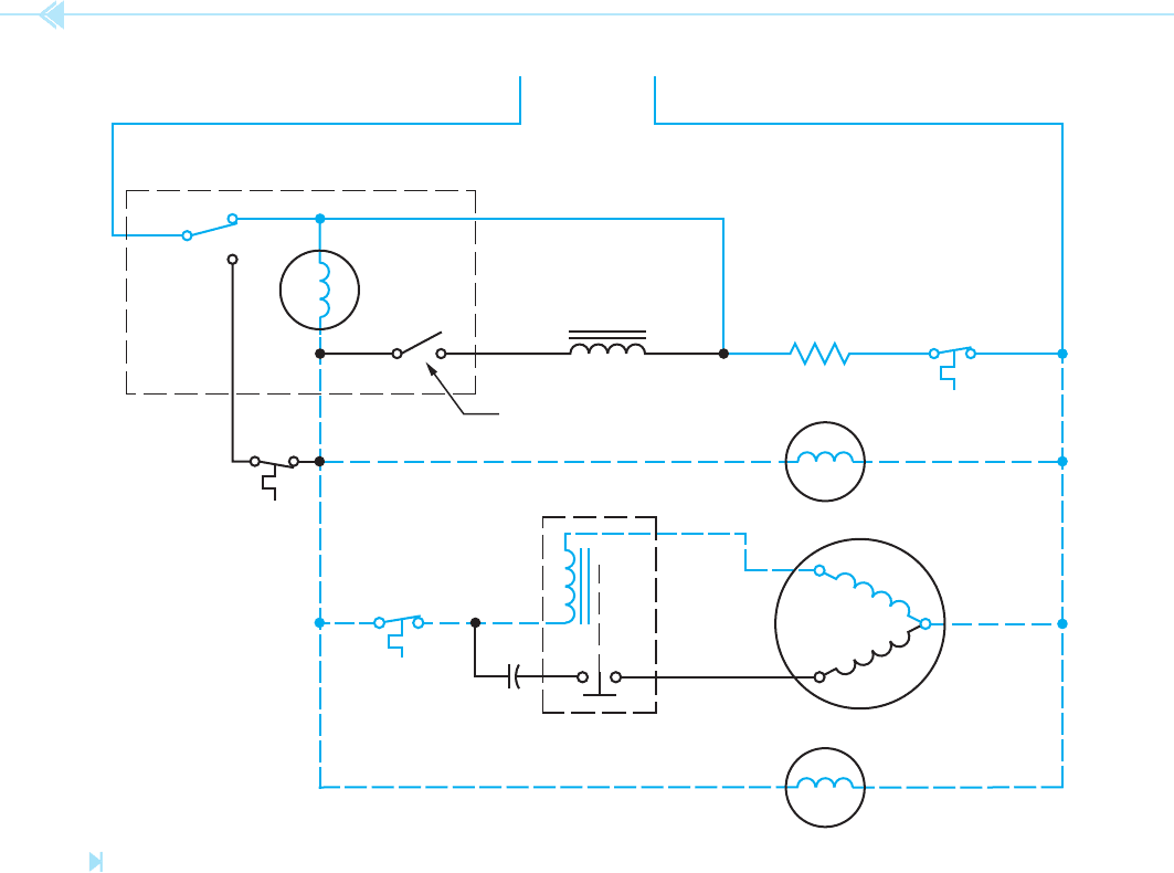
Figure 45–31
Defrost thermostat closes. (Source: Delmar/Cengage Learning)
heater, and defrost thermostat. Note that if the
cabinet thermostat should open during the water ll
cycle, the cycle will be interrupted until the cabinet
thermostat again closes.
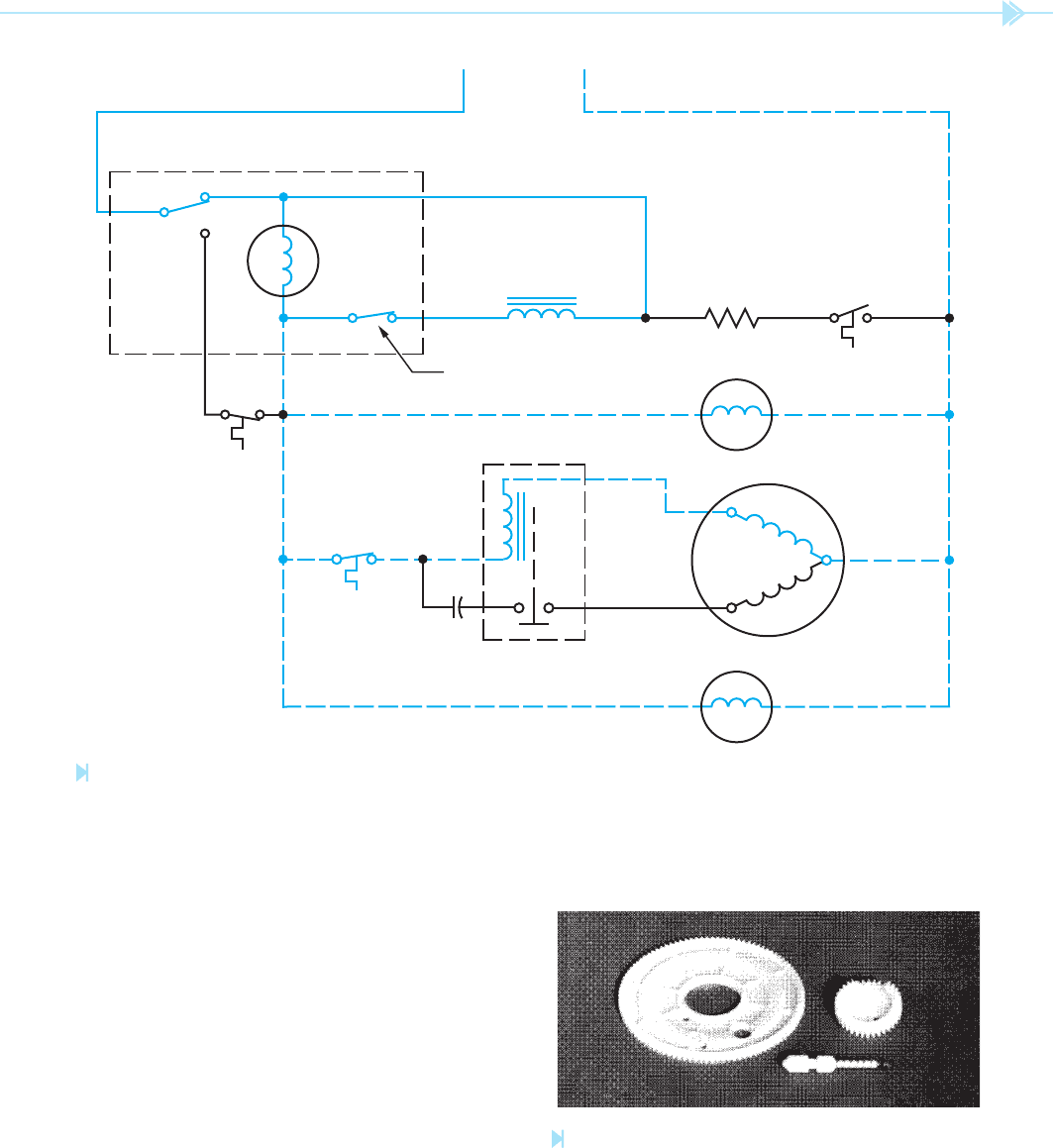
Because the timer motor is used to operate both
the ice maker and defrost cycle, it is possible for the
ice ejection cycle to occur during the defrost cycle,
Figure 45–34. Notice that a parallel current path
exists through both the timer motor and water sole-
noid valve. If the defrost thermostat should open
while the water valve switch is closed, the same
current path is provided through the evaporator
fan, compressor run winding, and condenser fan
for both the timer motor and water solenoid valve.
This permits the tray to dump the ice and re ll with
water.
UNIT 45 Household Ice Makers 431
WATER
SOLENOID
VALVE
120
VOLTS
DEFROST
HEATER
DEFROST
THERMOSTAT
EVAPORATOR
FAN
COMPRESSOR
CONDENSER FAN
RUN
START
TIMER
MOTOR
WATER FILL SWITCH
STARTING RELAY
OVERLOAD
CABINET
THERMOSTAT
START CAP.
DEFROST
TIMER
SWITCH
ICEMAKER
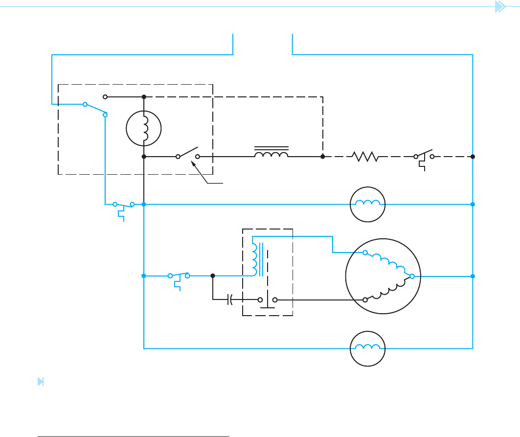
Figure 45–32
The defrost thermostat remains open until the temperature drops to 2°F. (Source: Delmar/Cengage Learning)
PROBLEMS AND PRECAUTIONS
WITH THE FLEX TRAY ICE MAKER
When servicing the ex tray ice maker, there are
several conditions the serviceperson should be
aware of:
1. Before disconnecting the ice maker, turn the
cabinet thermostat to the OFF position or
unplug the appliance. This is done to prevent
arcing at the terminal connector block.
2. If the ice maker should jam, it will prevent
the defrost timer from operating.
3. The ex tray type of ice maker permits no
adjustment of the water ll switch.
4. One of the most common problems is that the
surface of the ice tray becomes rough because
of mineral deposits in the water. This causes
the ice cubes to stick in the tray and not be
ejected. When ice cubes are not ejected, the
tray becomes too full during the ll cycle and
432 SECTION 7 Ice Maker and Refrigeration Controls
WATER
SOLENOID
VALVE
120
VOLTS
DEFROST
HEATER
DEFROST
THERMOSTAT
EVAPORATOR
FAN
COMPRESSOR
CONDENSER FAN
RUN
START
TIMER
MOTOR
WATER FILL SWITCH
STARTING RELAY
OVERLOAD
CABINET
THERMOSTAT
START CAP.
DEFROST
TIMER
SWITCH
ICEMAKER
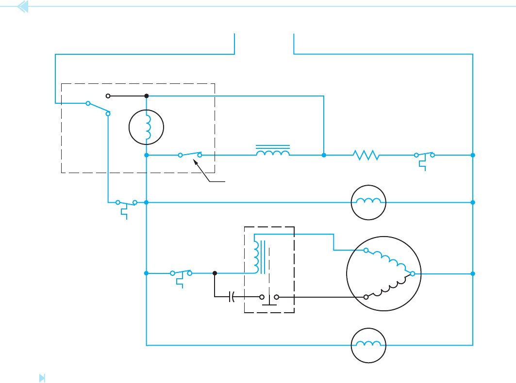
Figure 45–33
The water fi ll switch closes. (Source: Delmar/Cengage Learning)
UNIT 45 Household Ice Makers 433
WATER
SOLENOID
VALVE
120
VOLTS
DEFROST
HEATER
DEFROST
THERMOSTAT
EVAPORATOR
FAN
COMPRESSOR
CONDENSER FAN
RUN
START
TIMER
MOTOR
WATER FILL SWITCH
STARTING RELAY
OVERLOAD
CABINET
THERMOSTAT
START CAP.
DEFROST
TIMER
SWITCH
ICEMAKER
Figure 45–34
The ice ejection cycle can occur during the defrost cycle. (Source: Delmar/Cengage Learning)
Figure 45–35
Drive gear and pins for the fl ex tray ice maker.
(Source: Delmar/Cengage Learning)
causes a slab of ice to form. This slab can
cause damage to the pin, gears, and/or timer
motor. The ice tray should be replaced at the
rst sign of slabbing. A set of drive gears and
pin are shown in Figure 45–35.

434 SECTION 7 Ice Maker and Refrigeration Controls
SUMMARY
Ice makers can be divided into two major categories: household and commercial.
An electric solenoid valve permits the tray to be lled with water at the proper time.
A ow washer is used to meter the amount of water ow to the tray.
The ow control washer is designed to operate with pressures that range between 15 and
100 psi.
The amount of water needed to ll the mold or tray is approximately 135 cc or 4 oz.
A thermostat mounted to the mold senses when the water is frozen.
A mold heater is used to slightly melt the cubes so the ejector blades can push them out of
the mold.
The shutoff arm senses when the storage bin is full of cubes.
The shutoff arm can be used to manually prevent starting another cycle.
Flex tray ice makers operate by lling a exible tray with water. When the water freezes,
the entire tray rotates and dumps the ice in the storage bin.
The motors of ex tray ice makers are generally used to operate the defrost timer circuit.
KEY TERMS
cabinet thermostat
compact
defrost heater thermostat
ejector blades
ex tray
ow washer
holding switch
mold heater
test points
REVIEW QUESTIONS
1. Ice makers are divided into what two major categories?
2. What is the advantage of continually recirculating the water during the ice-making
process?
3. What component controls the amount of water ow into the original compact ice
maker?
4. Does the ex tray ice maker require a mold heater to thaw the ice cubes before they
can be dumped into the storage bin?
5. In the original compact ice maker, what method is used to sense when the water has
been frozen?
6. In the original compact ice maker, what controls the start of the ejection and re ll
cycle?
7. In the ex tray ice maker, what controls the start of the ejection and re ll cycle?
8. How can the original compact ice maker be manually turned off?

UNIT 45 Household Ice Makers 435
9. How many revolutions will the ejector blades of the original compact ice maker nor-
mally make during the ejection cycle?
10. What is the function of the holding switch in the original compact ice maker circuit?
11. Concerning the ex tray ice maker, what two separate tasks are performed by the
timer motor?
12. What is the function of the spring loaded pin in the ex tray ice maker?
13. Concerning the ex tray ice maker, is it possible for the timer motor to operate during
the defrost cycle?
14. Concerning the new type compact ice maker, what method is used to change the
contacts labeled A, B, C, and D in the schematic diagram shown in Figure 45–18?
15. Can the gear of the new type compact ice maker be rotated to manually advance the
operation of the ice maker?
16. How many revolutions do the ejector blades of the new type compact ice maker make
during the ejection cycle?

436
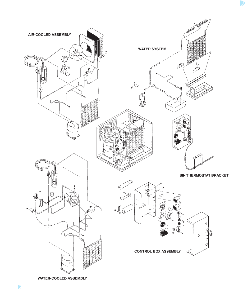
Commercial ice makers are designed to produce
large quantities of ice and are generally found in
restaurants, cafeterias, motels, and hotels. Some ice
makers produce cubes and others produce aked ice.
The rst commercial type ice maker to be discussed
is manufactured by Scotsman Company. The basic
components of this unit are shown in Figure 46–1.
Notice that this unit can be equipped with either an
air-cooled or a water-cooled condenser. The water-
cooled unit operates much more quietly.
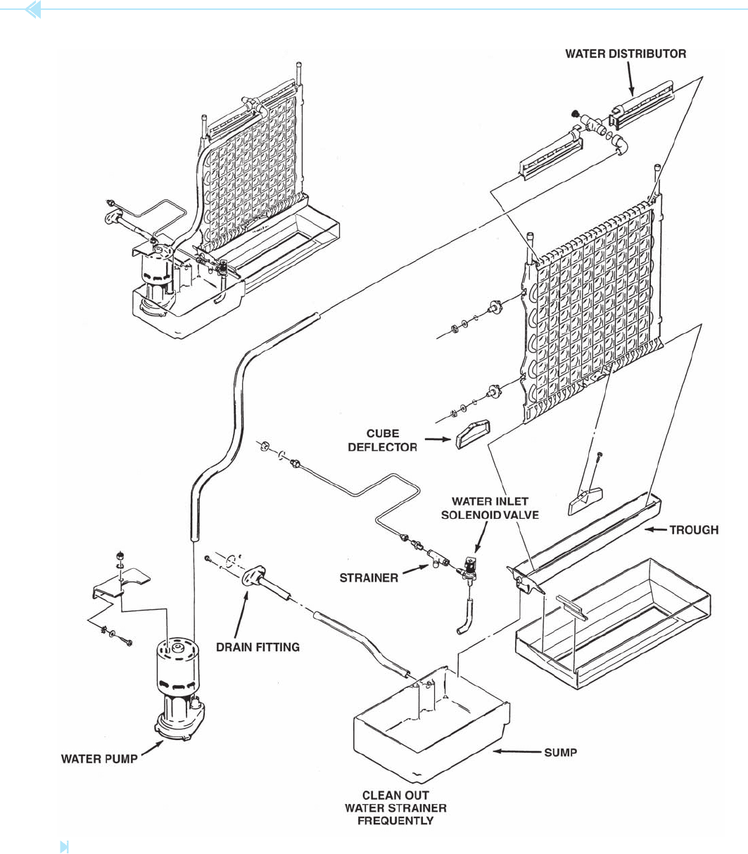
This unit produces ice by cascading water over
a metal plate used as the evaporator, Figure 46–2.
A water pump provides continuous circulation of
water when the compressor is operating. A water
distributor, located at the top of the plate, provides
an even ow of water over the entire surface of the
plate. Excess water is caught by a trough at the bot-
tom of the plate and is returned to a sump where
OBJECTIVES
After studying this unit the student should
be able to:
Discuss the basic design of different
types of commercial ice makers
Discuss the operation of a cube-type
and fl aker-type ice maker
Discuss the control system of a cube-
type and fl aker-type ice maker
Commercial
Ice Makers
UNIT 46
UNIT 46 Commercial Ice Markers 437
Figure 46–1
Scotsman cube-type ice maker. (Courtesy of Scotsman Ice Systems).
438 SECTION 7 Ice Maker and Refrigeration Controls
Figure 46–2
Water cascades over a metal plate to produce ice. (Courtesy of Scotsman Ice Systems).
UNIT 46 Commercial Ice Markers 439
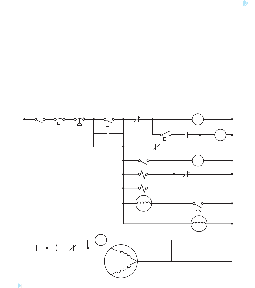
be diverted to the evaporator plate. This high pres-
sure gas warms the plate, and thaws the surface of
the ice that is in contact with it. The combination of
the warm plate and the cascading water loosens the
ice cubes so that they drop away from the plate and
fall into the storage bin below. During the harvest
cycle, a
water solenoid valve opens and permits
fresh water to
ow into the sump. This not only
re lls the sump, but also ushes impurities out the
over ow drain.
The basic electrical schematic diagram for this
machine is shown in Figure 46–3. There are two
manual switches in this circuit. One is the master
it is recirculated by the pump. Continuous circula-
tion of water produces a clearer ice because pure
water freezes faster than impure water. This is not
to say that water can be puri ed by circulating it.
The puri cation is a result of the freezing process.
Basically, the water freezes before the impurities
and minerals have a chance to freeze. The water,
minus the impurities and minerals, is frozen to the
evaporator plate and the impurities and minerals
are returned to the sump.
After the ice has formed, the harvest cycle begins.
At the beginning of this cycle, a
hot-gas solenoid
valve opens and permits high pressure hot gas to
PUMP MOTOR
COMPRESSOR
STAR
T
RUN
HIGH
TEMP.
CUTOUT
HIGH
PRESS.
CUTOUT
MASTER
SWITCH
L1 N
FAN MOTOR
HIGH PRESS.
FAN CONTROL
PSR
POTENTIAL
STARTING
RELAY
PSRC
START CAP.
FR2
HOT–GAS SOL.
WATER SOL.
TMR1
BIN
THERMOSTAT
FR3
TMR2
FR1
FR4
CUBE SIZE
THERMOSTAT
COMP.
SWITCH
FR
FINISH
RELAY
TMR
TIMER
MOTOR
C
COMP. CONTACTOR
Figure 46–3
Basic schematic diagram of a commercial ice cube maker. (Source: Delmar/Cengage Learning)